|
|
Post by turbochris on Jun 3, 2013 11:52:01 GMT -5
where to inject it?
|
|
|
|
Post by Johansson on Jun 3, 2013 12:55:27 GMT -5
 The only practical place on my engine is through the inducer, a solid cone spray nozzle fitted inside the air box aimed directly at the compressor. I won´t run any winter races with the bike so no risk of icing. If there was more room it would perhaps be better to fit a small spray nozzle in each comp diffuser duct but the plumbing alone would be a total nightmare.  Cheers! /Anders |
|
|
|
Post by racket on Jun 3, 2013 17:03:46 GMT -5
Hi Chris/Anders
Before you both get too excited there are a few differences between an 8:1 PR engine and ours when it comes to inlet injection and thrust increases , with 8:1 the temp rise during compression is high enough to boil the water , the latent heat of phase change will reduce the temps in the final stages and reduce their work loads leaving more power for making thrust , ...............our relatively low compression ratio as well as the much shorter time frame within the comp reduces the evaporation significantly and the potential power gains :-( ................very fine atomisation of a water/methanol mix well forward of the comp face would be my choice, this will increase the time frame and hopefully reduce the air temps going into the comp, the increased density of the air will increase the mass flow and the reduced "relative" workload of the comp from the reduced temps will leave more pressure for making power , the reduced temps will also mean a higher pressure ratio once rpm are corrected for the lower inlet temp , again adding to power output.
If the solid cone spray nozzle was pointing into the air flow, to increase the time frame , and delivery pressures of >500 psi will produce a "mushroom" of spray at your airbox inlet, that should give several milliseconds for evaporation .
With the correct water/methanol mix ratio your fuel scheduling won't need changing .
The example given had a relatively low turb inlet temp of 2000 R - 1540 F - 837 C , and combined with the high pressure ratio would have meant relatively low TOTs and a relatively low specific thrust , thus making the afterburning more effective than on our engines with a higher TOT .
With a lot of water injection theres a need for the turbine stage to be sized for the extra steam volumes otherwise the comp might surge .............lots to be considered :-)
Cheers
John
|
|
|
|
Post by Johansson on Jun 5, 2013 0:55:03 GMT -5
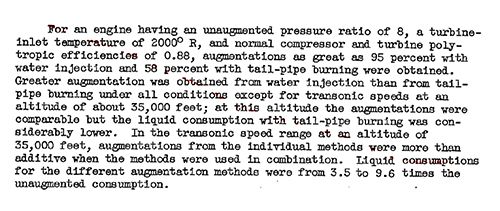
Good thing you took me back down on earth John, I almost wet my pants when I saw the 95% thrust increase figure.  The water injection system will be built later when I have run the engine, I need to figure out just how large a water tank I can build around the rear wheel since that will determine how long I can run augmented. Anyway, I´ve got a fair bit of work done the last couple of days. All of the oil lines are made and some of the fuel lines as well, it is starting to look like a mess and there is more to come. 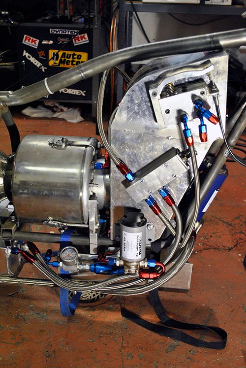 Here is the last oil line from the filter to the engine. 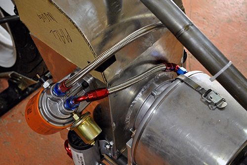 I also made an AN4 coupling for the fuel pump. 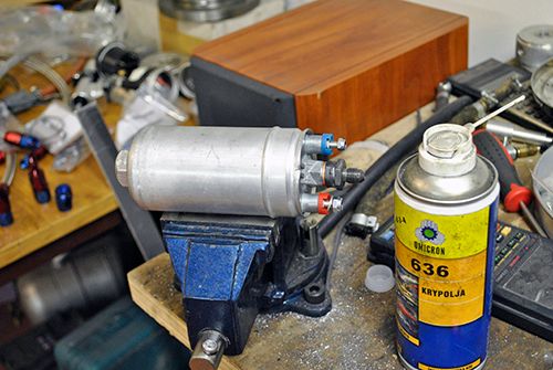 In order to finish the fuel lines I had to fit the fuel pump to the frame, I *could* just weld a bracket to the frame and fit it with hose clamps but why always take the easiest route? 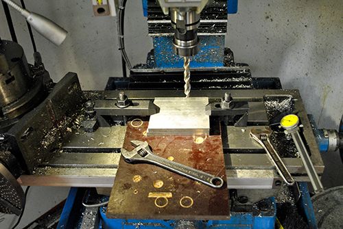 Two 10mm aluminum plates were stacked on top of each other and the fuel pump bracket build started. 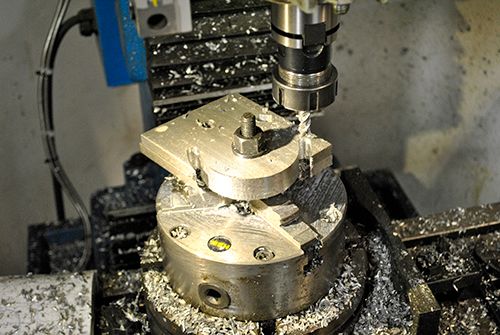 Just finished the outer profile. 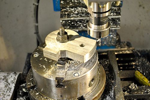 Milling the spots where M6 bolts will hold the frame clamp. 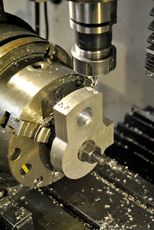 What fucking clamp I hear you think, why the one I am cutting loose right now of course! 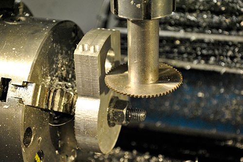 To make life easy I did as much as possible without removing the parts from the rotary table, here I am cutting the slot for the pump clamp. 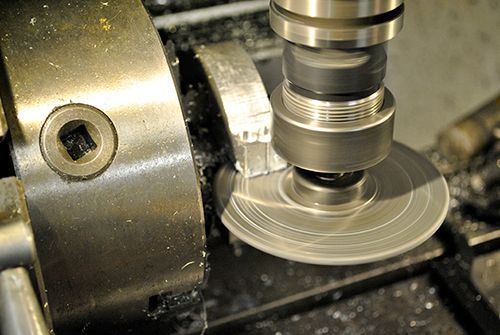 After laying the rotary table down I could mill the hole for the fuel pump. 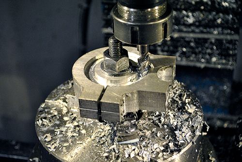 The last .10`s I took away with the arbor tool, notice the washers under the frame clamp so I can tighten it later. 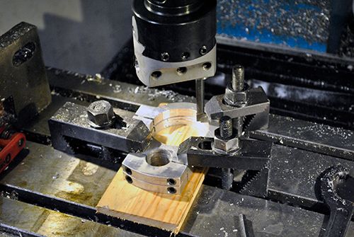 After separating the two brackets and filing the worst edges away they looked this fancy. 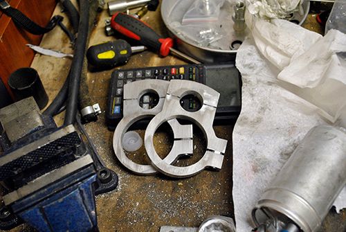 And with the pump fitted: 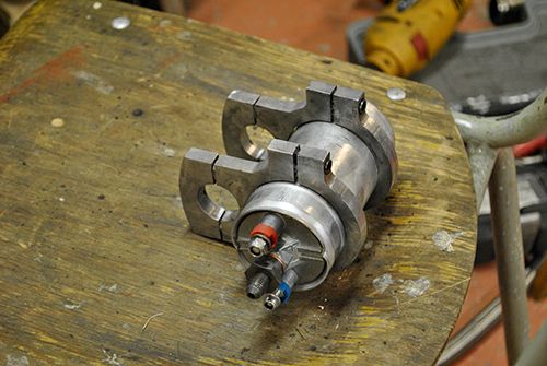 Here the pump is in place with the AN4 fuel line connected, it took some effort but looks a bit better than hose clamps in my opinion. 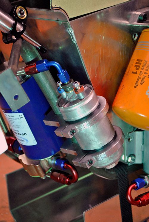 Cheers! /Anders |
|
|
|
Post by racket on Jun 5, 2013 4:01:00 GMT -5
Hi Anders
Now they are a couple of fine looking pump clamps ..............adds that personal touch :-)
Yep , bike is starting to have the usual clutter of plumbing , looking serious.
Heh heh , you'll suddenly have it finished at this rate of progress .
Cheers
John
|
|
|
|
Post by Johansson on Jun 5, 2013 9:54:22 GMT -5
Hi John,
As soon as I have the fuel tank finished there is "only" the gearbox mods that needs to be done before I can feed her some kero, I will visit my job on monday (I am on children leave so no work until September for me) and cut out the aluminum sheets for the fuel tank and the last part for the air box.
Cheers!
/Anders
|
|
|
|
Post by turbochris on Jun 5, 2013 10:28:07 GMT -5
I just hose clampped my pump to the frame like a lazy bitch.......
About that water injection, if we used a GPU w an oversized turbine could we make up for it w water? Get it up to high tit wo putting a load on the output shaft?
|
|
nersut
Veteran Member

Joined: September 2012
Posts: 223
|
Post by nersut on Jun 5, 2013 10:53:52 GMT -5
Hi Anders Great progress on the build. I am looking forward for the first start up video. I check the JATO site every day and read all the good reading you post. Cheers Erik |
|
|
|
Post by Johansson on Jun 5, 2013 15:22:32 GMT -5
I just hose clampped my pump to the frame like a lazy bitch....... About that water injection, if we used a GPU w an oversized turbine could we make up for it w water? Get it up to high tit wo putting a load on the output shaft? More time for beer drinking then, probably a smart move. The "problem" with water injection as I see it is the huge water consumption, the engine has to work ok at all loads without water since you´ll run out of it sooner or later. Hi Anders Great progress on the build. I am looking forward for the first start up video. I check the JATO site every day and read all the good reading you post. Cheers Erik Thanks Erik! It will probably take most of the summer to ready the bike for a test run, I have been there too often to think it will be quickly done. There is always a pile of stuff that you forgot about that has to be done first. Cheers! /Anders |
|
|
|
Post by finiteparts on Jun 9, 2013 22:39:22 GMT -5
Anders, nice work as always!
Another issue to consider with water injection is the erosion that is experienced if the droplets do not fully evaporate. Since water does not behave compressibly, droplets hitting the compressor wheel are equivalent to small pebbles that will erode the leading edges... if the droplet mass and the velocity difference between the blade and droplet are large enough, damage can occur.
Large industrial engines often used water injection (inlet foggers) for power augmentation to recover load capability lost on hot day operation... Inlet foggers often use standard pressure swirl atomizers that produce very fine droplet distribution, but there are some well known cases were the inlet foggers use a impingement pin style atomizers and the wake behind the pin cause droplets to coalesce into larger drops that make it into the early compressor stages.
Foggers typically produce droplets smaller that 40 microns and produce a true fog. If the atomizer that you use produces a mist that falls quickly to the ground, you could get erosion. It is said that a 10 micron drop will fall to the ground in 5 mins in still air due to Brownian motion caused by the interaction with air particles. So, very small droplets will travel along with the same relative motions of the local airflow, which will give a very small velocity gradient between the blades and air. Large drops would not follow the airflow well and thus give a very large velocity discrepancy between the drop and the blade. One vendor gives the air to water mass ratio as 0.6 to 1 (volume ratio 500:1)...with those mass ratios, the equations should be reworked to account for the increased mass flow through the engine. The increased mass flow through the engine can increase the back pressure from the turbine, which would likely drive the compressor operating point closer to the surge line. If the dry operating point of the compressor didn't have enough surge margin to support the increase in pressure experienced during the fogging, surging could occur.
Other forms of power augmentation for large industrial engines is to inject the water or steam into the compressor discharge casing or into the combustor. The combustor inject is often used to also reduce the peak flame temperature and thus the oxides of nitrogen formed.
Additionally, these engines typically use stainless steel first stage compressor blades, which are much more rugged than aluminum compressor wheels...
So I think that if you can get small enough droplets and keep them from coalescing on the inlet wall (and forming larger droplets that may get drawn into the compressor), it should work well without causing leading edge erosion.
|
|
|
|
Post by Johansson on Jun 10, 2013 16:42:09 GMT -5
Interesting! I will use standard Danfoss spray nozzles and a Bosch 044 copy capable of up to 8 bar, so there should be a fine enough mist entering the compressor. The run time with water injection will be measured in minutes rather than hours so even if there is some erosion it will hopefully not have time to do any major damage to the inducer tips. 0.6:1 air/water mass ratio sounds extremely high to me, in that case won´t I be feeding the engine almost 2 litres of water per second? Injecting water into the diffusor stage or combustor is another option, takes more work though since I will have to modify the engine a bit so I will try injecting upstream the compressor first at moderate mass flows to see how the engine reacts. One downside is that I won´t be able to run the engine up to full power stationary with the freepower attached and no ram air feeding the air box, so I will have to try it the hard way on the open road. Should make for some interesting evenings next summer. |
|
|
|
Post by racket on Jun 10, 2013 18:57:21 GMT -5
Hi Anders
Yeh , ~2-2.5 litres per minute of a mix of 2 parts distilled water and 1 part methanol would be a reasonably level to start with , I'd be inclined to used 4 or 6 small solid cone spray nozzles setup at the entrance to your "airbox", the smaller nozzles will maximise the atomisation compared to a single large nozzle and probably provide a better coverage of your airbox inlet area .
The water injection system for the Allison 250 C18 engine uses 40 psig pressure at the multiple atomisers with its 2:1 ratio of water/methanol , it uses 90 psi P2 air to pressurise its fluid container, there must be a pressure reducer somewhere in the line , or perhaps the 0.124" dia restrictor in the delivery line does the pressure reducing for downstream . ...........the Allison flows ~1.2 - 1.3 gallons per minute of water/alky for its 3-3.6 lbs/sec air flow , assuming the water/alky mix weighs in at ~8 lbs/gallon ( not sure if my info is in US or Imperial gallons) , but the water/alky flow would be ~10-12 lbs/min for a flow of say 200 lbs of air , so an ~ 20:1 air/water ratio ( 5%) by weight .
With your ~140 lbs/min of air that'll mean ~7 lbs/min of water/alky , so your 044 pump should do the job nicely :-)
When I tried water injection with the TV84 turbo I used a windscreen washer pump to feed a ring of hole drilled in a tube surrounding the FOD screen situated ~100mm from the inducer , atomisation?? was very crude with some relatively large droplets impacting the inducer , there was some erosion of the inducer, but due to the limited duty cycle of the injection it wasn't a problem, with finer atomisation taking place a lot further upstream , you should be OK .
Cheers
John
|
|
|
|
Post by Johansson on Jun 11, 2013 0:44:16 GMT -5
Hi John, 2-2.5L/minute sounds a bit better. It will be very straightforward to fit a spray nozzle grid at the air box mouth, I will also add a drain at the bottom in case the pump is accidently started so it won´t fill the engine with water. I shouldn´t need more than 5 litre tank capacity then since I will only use the water injection at full throttle during the run, 2 minutes of full throttle should hopefully have covered the whole track. Cheers! /Anders |
|
|
|
Post by racket on Jun 11, 2013 4:17:25 GMT -5
Hi Anders
Yep , 5 litres will be plenty :-)
You probably only need it for the last bit of the run into , and through , the measured distance , probably a minute at the most , the measured mile will take <20 seconds ;-)
Cheers
John
|
|
|
|
Post by turbochris on Jun 11, 2013 11:53:48 GMT -5
I've been considering a 50/50 water alcohol mix sprayed into my nimbus but the thing is so surge prone already is it worth a try? I have variable IGV's maybe I need to control them better? The atmospheric Rube Goldberg Archimedes based piece of shit that controls them now could obviously use some improvement........
|
|


