jettoymaker
Junior Member

Joined: September 2010
Posts: 55
|
Post by jettoymaker on Jun 22, 2013 4:23:05 GMT -5
Hi Anders, Finally after 6 months I got a day off without having to be sick LOL Thought I would have a look at the progress so far for myself, as Mark and John have been telling me all about it. Shit you are a prodigious workers...!!! I thought some of the other guys in here were hard working. It's all looking very sweet...makes mine look very stayed and predictable. Am hanging out big time to see it going  Will try and look in a bit more where ever possible as some of the designs you've come up with would have been better in B1 I think. |
|
|
|
Post by Johansson on Jun 22, 2013 16:18:57 GMT -5
Hi Andrew, Well, I wouldn´t say that predictable is something negative when it comes to a turbine bike.  It is coming together in a slow and steady pace, if I would speed up the development my family and other interests would suffer and that would never do so I will keep building whenever I have time until the bike is ready to hit the tarmac. I hope I can have it ready for racing next summer when the One Mile race in Tierp goes off, that will be a good opportunity to find out what the bike is capable of. My friends gave me a GPS logger for my 30 year birthday so I can see exactly how the bike accelerates through the mile and change the gearing to peak the freepower turbine RPM at the finish line. Take care! /Anders |
|
|
|
Post by Johansson on Jun 24, 2013 16:40:48 GMT -5
Mats Eriksson who runs ME Racing (pro mod dragracer here in Sweden) has donated 4.5 meter 0.5" chromemoly tubing for the build, thanks a lot! 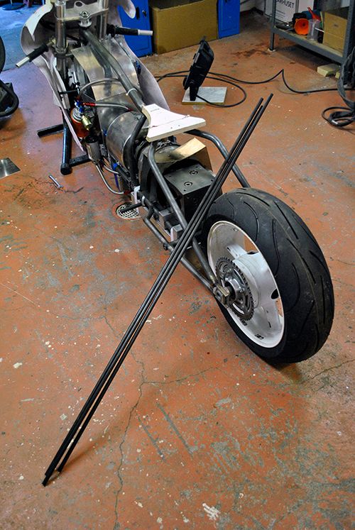 Tonight I got a bit further with the fuel tank, it was a bit tricky to streamline the front of the tank but I think it will turn out ok in the end. First I tacked the bottom piece in place to have something to relate to. 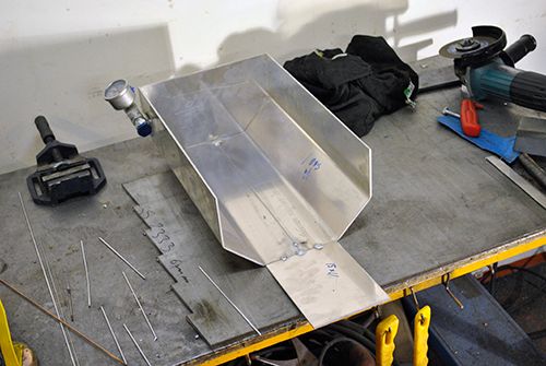 Rolling the front of the fuel tank. 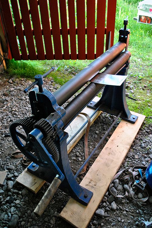 After that I cut it to shape. 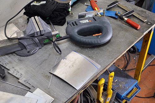 Next up was to weld it to the tank and get the angle right so the radiuses of the tank and the front wheel align. 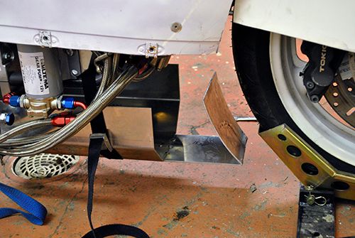 One more piece in place. 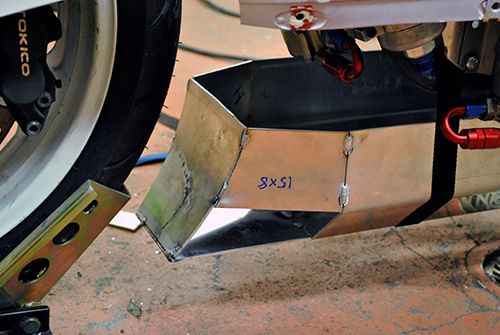 Quite some hammering and bending was required to get the right shape for this piece... 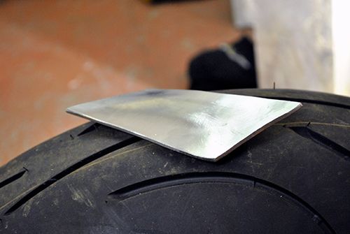 ...which fits in the last gap. The piece for the other side of the tank will have to wait since time was running late, as soon as I have gotten some house painting done that I didn´t bother to do last year I will continue on the tank build. 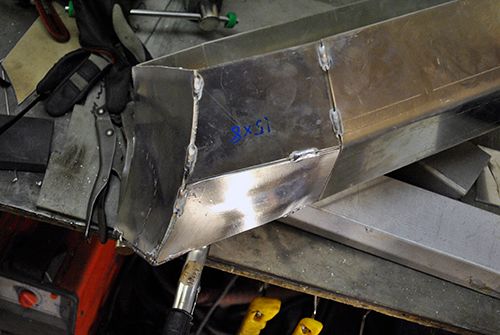 Cheers! /Anders |
|
|
|
Post by racket on Jun 24, 2013 17:25:40 GMT -5
Hi Anders
Those compound curves are a bugger to make .
Back to those paint brushes and finish it off otherwise the unpainted bits will be staring you in the face until they're done , I've got some concreting work on today , work around the house never finishes.
Cheers
John
|
|
|
|
Post by Johansson on Jun 26, 2013 8:15:54 GMT -5
Misery! Just when I was about to start painting the clouds opened and rain started pouring down. Oh well, might as well head out to the shed then.  The second "compound curve" part is made and tacked into place. 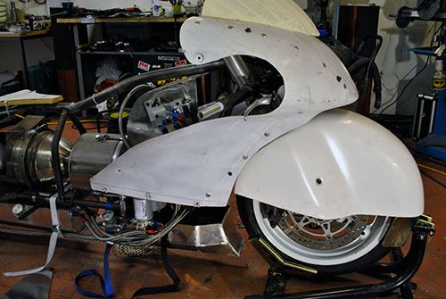 Next week I will visit my job to cut out the tank top and after that I can weld the filler neck and fittings to the tank. 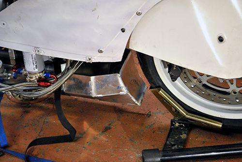 I´ve also made a bracket for the steering damper. 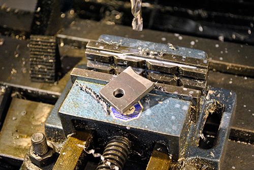 Here it is fitted, I need it to meet the class regulations and even if I didn´t have to I would still want one. 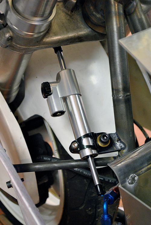 Cheers! /Anders |
|
|
|
Post by ernie wrenn on Jun 26, 2013 16:38:56 GMT -5
I FINALLY found a flaw on the build. The very center of the wield and end, you touched the tungsten. YES...
Very good job!
|
|
|
|
Post by racket on Jun 26, 2013 18:34:50 GMT -5
Hi Anders
You'll appreciate the damper if you ever get a high speed wobbly starting to generate , they've save my arse a few times when I've done something stupid, your's too I'd recon, build progressing beautifully :-)
Ernie , LOL......well spotted .................hopefully , yes , so we can mark him down to 99.99% now ;-)
Cheers
John
|
|
|
|
Post by Johansson on Jun 26, 2013 23:01:24 GMT -5
I FINALLY found a flaw on the build. The very center of the wield and end, you touched the tungsten. YES... Very good job! Thanks Ernie! You must have missed the oil tank welds then, there was more dipping going on there than in a 3 hour Rocco Siffredi DVD...  Hi Anders You'll appreciate the damper if you ever get a high speed wobbly starting to generate , they've save my arse a few times when I've done something stupid, your's too I'd recon, build progressing beautifully :-) Ernie , LOL......well spotted .................hopefully , yes , so we can mark him down to 99.99% now ;-) Cheers John I´ve never experienced one myself but I´ve seen videos of people getting trapped in those and it cannot be easy to sort out while remaining on both the wheels and the road... |
|
|
|
Post by Johansson on Jun 27, 2013 16:30:42 GMT -5
Tonight I made the oil tank brackets and hung it in place, first I made some steel brackets and welded two of them to the rear of the frame. 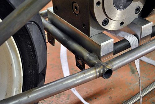 Aluminum brackets were made to fit and were welded to the tank. 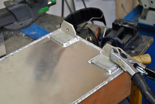 The same procedure was made for the front brackets, here the tank brackets are cooling off after welding. 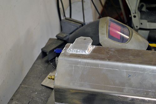 And a while later the tank was securely in place, feels sturdy enough I think. 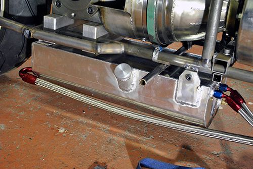 And a pic from the rear. Next up is to finish the fuel tank, I will cut some sheet aluminum for it after the weekend. On saturday we are off visiting a hot bulb engine exhibition, might down a few beers as well to keep the erection in control. 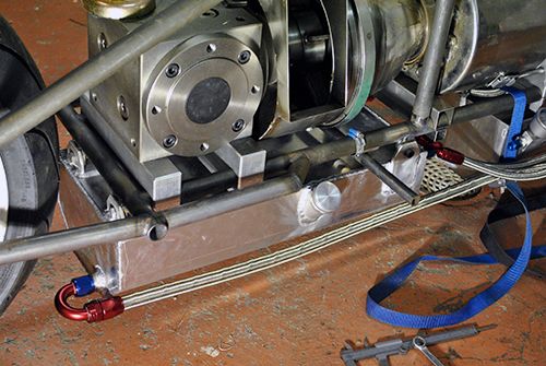 Cheers! /Anders |
|
|
|
Post by Johansson on Jun 28, 2013 14:01:18 GMT -5
With the girls playing around in the water puddles in front of the workshop I had the opportunity to combine babysitting and bike building! I decided to cut out the air intake on the front fairings, I need to do it before I can build the dashboard for all the gauges. 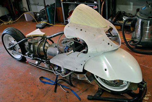 A 3mm aluminum strengthening plate was fitted before I cut the hole just in case the fairings would collapse, not much glass fiber left above the hole. 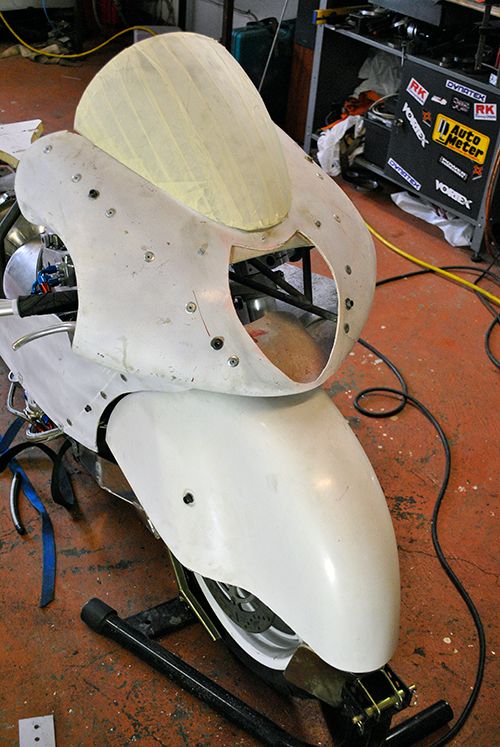 With that done I made an air deflector plate and welded it to the strengthening plate to get the ram air directed down into the engine air intake. Not the easiest piece to take a picture of but you get the idea. 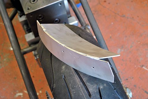 And it fits like this, later I will fit a black coarse meshed net to improve the looks a bit. 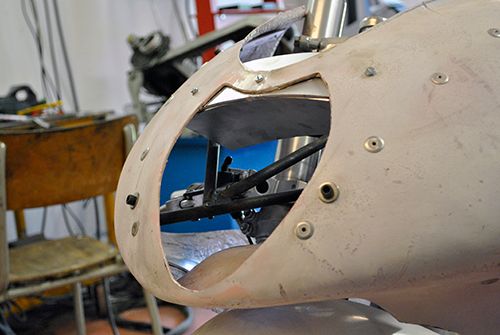 Cheers! /Anders |
|
|
|
Post by Johansson on Jul 1, 2013 15:22:52 GMT -5
Today I solved the problem with fastening the front sprocket to the gearbox output shaft!  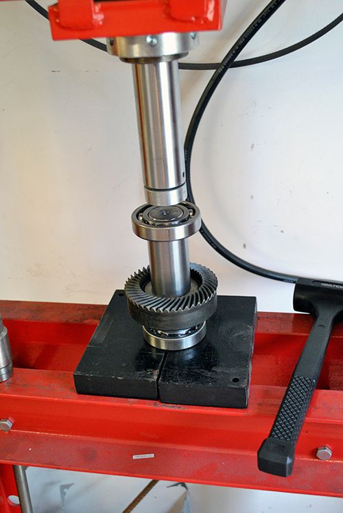 My earlier idea was to hire a mechanical company to cut splines on the shaft and have a friend of mine to spark erode internal splines in a sprocket blank, both expensive and troublesome so I did a test today with an old hayabusa sprocket I had laying around. I opened up the centre hole in the lathe and milled a 10mm slot for the woodruff key. 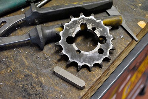 This sprocket had lots of holes drilled in it but when I make the "real" one I will use an undrilled sprocket, with a spacer behind it I can align the front and rear sprocket perfectly and another spacer outside the sprocket locked in place with an M10 bolt in the threaded hole in the shaft will make everything rock solid. Since there will be a smooth, constant torque I cannot imagine that it won´t be sturdy enough. 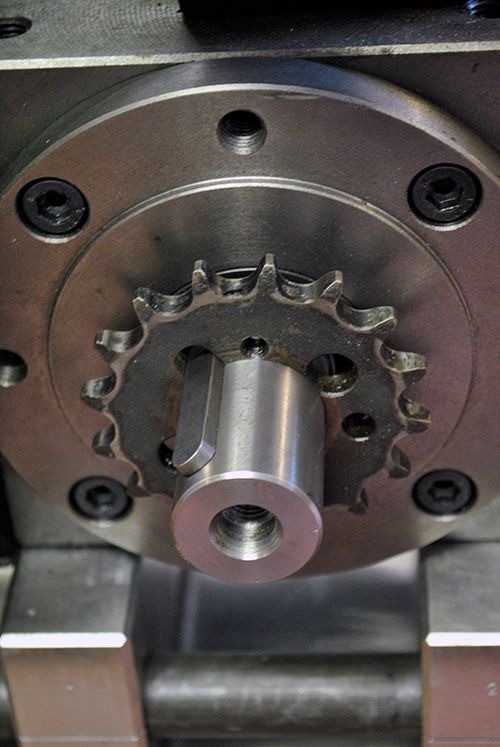 This was the only detail left unfabricated that I didn´t know how to make so this is a big step forward for the project, the best thing about it is that the gearbox shafts are left unmodified so if I need to change them for some reason I won´t have to go though some expensive machining job again. I have also recieved a front brake cylinder for a GSXR750 identical to the one I already have, this one fits upside down on the left handlebar and will maneuver the rear brake. 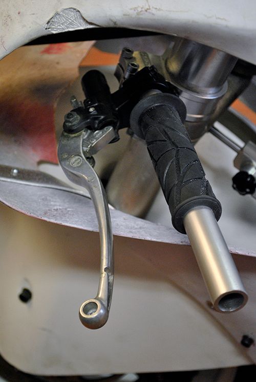 Cheers! /Anders |
|
|
|
Post by racket on Jul 1, 2013 17:38:48 GMT -5
Hi Anders
With your sprocket setup, an easier method might be to use a standard industrial sprocket , this is what I did with my first bike , I might have had to thin down the thickness of the teeth to accommodate the bike chain width but thats about all as the sprockets come neatly bored for standard shaft sizes , I then used a couple of grub screws onto the key to hold the sprocket in the correct position axially on the shaft, I didn't have a tapped thread in the shaft so had to rely solely on the grub screws, your shim setup will be much more secure as you'll be able to lockwire the screw to the sprocket
The industrial sprockets have a boss on the side that increases the length of keyway in contact with the key compared to your current setup, might be worth checking out for a simple solution , buy a few different teeth numbers for easy gearing changes :-)
One other thing I forgot to mention the other day , you might need to allow for expansion of your long alloy oil tank , with hot oil it'll expand a millimetre or two , maybe a bit of extra clearance on those front bolt holes along with loosely nipped up bolts so the tank can expand and slide a bit rather than bend your brackets or potentially split the tank if it distorts .
Getting closer every day :-)
Cheers
John
|
|
|
|
Post by Johansson on Jul 2, 2013 14:50:16 GMT -5
Hi John, What is the industrial name for a 520 sprocket? That would certainly be a good method if I can find the right sized sprocket, will look into it further. Very good idea to allow for tank expansion, luckily the rear mount is fitted sideways so if I leave a 1-2mm play for those bolts it can expand as much as it wants. I got the battery for the bike today! A 52Ah Deka Dominator deep cycle battery made for total loss systems so no cranking battery. 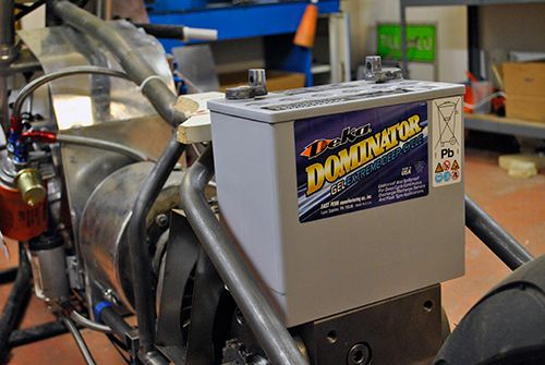 The lid for the fuel tank is also finished so as soon as I can I will start figuring out where to place the tank connections. 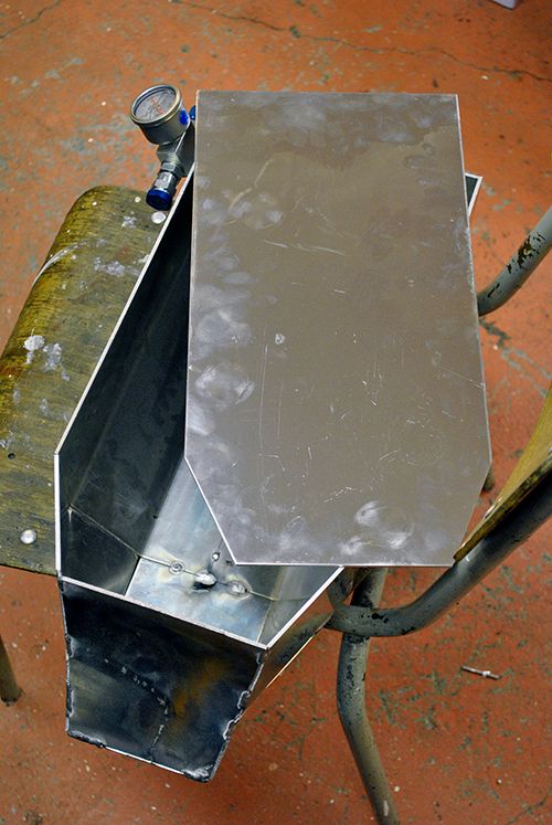 Cheers! /Anders |
|
|
|
Post by racket on Jul 2, 2013 16:49:07 GMT -5
Hi Anders
From what I remember a 520 chain is a 5/8" X 3/8" chain , its just the width thats often different between industrial and bike chain , bike have the narrower section .
Nice battery , that'll keep the pumps going :-)
Cheers
John
|
|
|
|
Post by enginewhisperer on Jul 3, 2013 8:52:03 GMT -5
I used industrial sprockets too, but machined the teeth off and welded the bike sprocket onto the hub |
|


 Will try and look in a bit more where ever possible as some of the designs you've come up with would have been better in B1 I think.


