|
|
Post by Johansson on Sept 15, 2013 23:02:39 GMT -5
That one looks even better, I think I´ll order one and give it a try before I mill anything away from the gearbox mount. Yesterday I had some time to work on the engine while the family was away, and I managed to squeeze in a couple of hours before I went to bed as well. 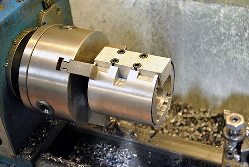 The oil distributor was fitted to the shaft tunnel to get its ends trued in the lathe, they need to be perfectly in line with the shaft tunnel sides. 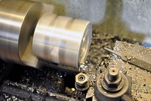 After that I drilled the mail oil channel that connects the two journal bearings and the thrust bearing. 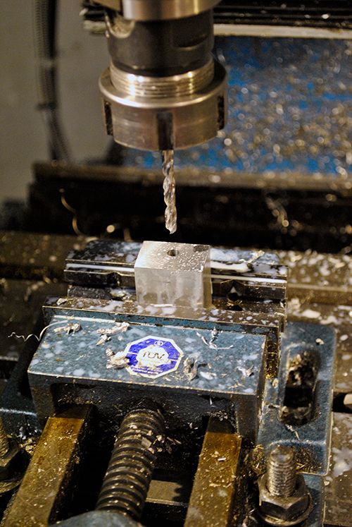 After drilling the journal bearing feed holes the distributor block looked like this. 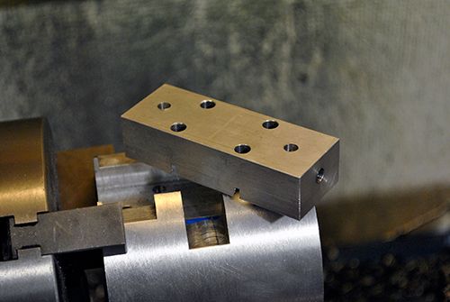 Here it is fitted to the shaft tunnel, the hole in the end feeds oil to the thrust bearing. 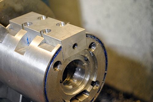 The oil needs to get in to the distributor block somehow, so I drilled a hole in the side and gave it 1/2" UNF threads. A steel rod was threaded and will have a steel oil line welded to it. I had to make a custom die holder first since I didn´t have anyone that fitted the 1/2"UNF die. 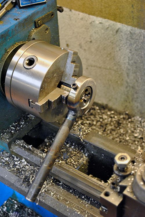 Here it is partially fitted to the oil distributor block. 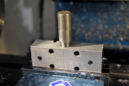 To make the distributor block a bit less ugly I took the corners away in the lathe so its radius would follow the shaft tunnel. 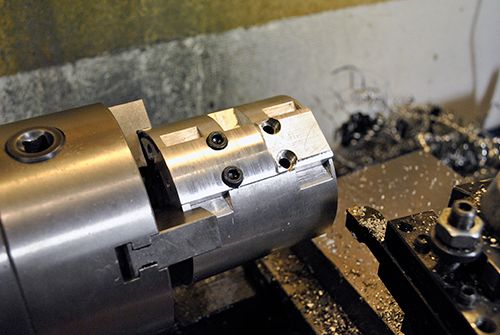 And here is the result, the only thing left to do with this part is to drill the bolt heads for lock wire and cut O-ring grooves for the three oil holes. I have ordered a bag of silicon O-rings so as soon as they arrive I can try to figure out how to make a tool to cut the grooves with. 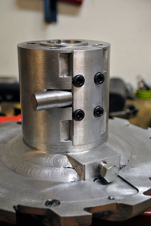 Cheers! /Anders |
|
|
|
Post by racket on Sept 16, 2013 0:19:55 GMT -5
Hi Anders
With your O'rings , perhaps just mill a "pocket" for the O'ring's OD to snugly fit into, with the pocket's depth adjusted so that the O'ring sits a bit proud of the metal surface and can be squashed down when the parts are screwed together , the oil pressure forcing against the ID of the O'ring should also help keep things sealed .
Cheers
John
|
|
|
|
Post by Johansson on Sept 16, 2013 1:51:42 GMT -5
Hi John,
My idea is to make a steel sleeve that fits inside the, somewhat opened up, oil hole that the ID of the rings can rest against.
Without it there would be a risk that the rings dislocates while torqued down and drops into the oil hole, don´t you think?
Cheers!
/Anders
|
|
|
|
Post by racket on Sept 16, 2013 4:12:57 GMT -5
Hi Anders
Yeh, if you've got room for a steel sleeve it'll certainly make O'ring positioning more positive :-)
Cheers
John
|
|
ripp
Veteran Member
   I'm sorry, I don't speak english, so I torment you (and myself) with a translation program,Sorry
Joined: January 2013
Posts: 237
|
Post by ripp on Sept 16, 2013 13:03:08 GMT -5
Hi Anders, As always, a perferkt working at the lathe / milling machine. One question, why do you need this supply line between the bearings? These are but the usual way from the front hole with supplies. Or I do not understand correctly ? www.universalauto.com/turbo-super/turbocharger_cut-away.jpgCheers Ralph |
|
|
|
Post by Johansson on Sept 16, 2013 13:57:57 GMT -5
John: I should be able to squeeze one in there. Don´t want any more trouble with the bearings after this overhaul...  Rip: Thanks!  I am not sure I understand exactly what you mean, but I will block off the old supply hole directly above the thrust bearing and use the new one between the two journal bearings. This is because it is easier to fit the supply line there, I was forced to use a leaking banjo fitting in the old place due to space limitations. Cheers! /Anders |
|
ripp
Veteran Member
   I'm sorry, I don't speak english, so I torment you (and myself) with a translation program,Sorry
Joined: January 2013
Posts: 237
|
Post by ripp on Sept 16, 2013 14:24:17 GMT -5
Anders: do you have open the link , then you can see how the oil is going
(yellow painted).
there is only one pressure line to all the bearing and only one seal
at the beginning.
Cheers
Ralph
|
|
|
|
Post by Johansson on Sept 16, 2013 15:01:09 GMT -5
Hi Rip, My oil lines are routed the same way as the ones in your link, the only thing that differs is that the shaft tunnel in the link is all in one piece while my shaft tunnel had to be modified hence the three seals.  In this pic you can see the half finished oil feed rod (stupid name but I don´t know what else to call it) where the oil enters the distributor block, the two oil holes to the journal bearings and just barely the hole in the side of the block that feeds the thrust bearing. The other four holes are for the mounting bolts. Cheers! /Anders |
|
ripp
Veteran Member
   I'm sorry, I don't speak english, so I torment you (and myself) with a translation program,Sorry
Joined: January 2013
Posts: 237
|
Post by ripp on Sept 17, 2013 11:52:57 GMT -5
Anders: I understand it now  Cheers Ralph |
|
|
|
Post by Johansson on Sept 18, 2013 14:11:55 GMT -5
New brake discs arrived today, the old ones looks more like a pair of wave washers...  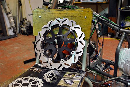 Cheers! /Anders |
|
|
|
Post by racket on Sept 18, 2013 15:33:53 GMT -5
Hi Anders
Can't have enough brakes................nice discs :-)
Cheers
John
|
|
|
|
Post by Johansson on Sept 21, 2013 12:09:40 GMT -5
This weekend the rest of the family are away, so I have three whole days for myself. A strange feeling for someone with small kids, I spent the whole day in the workshop and got a fair bit of work done. 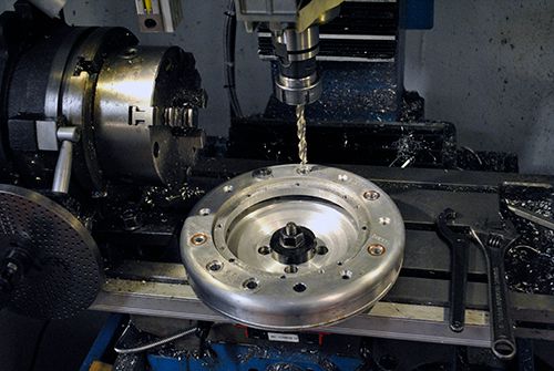 I made the oil pressure tube that goes through the compressor housing and an AN6 fitting that is threaded to fit the tube. 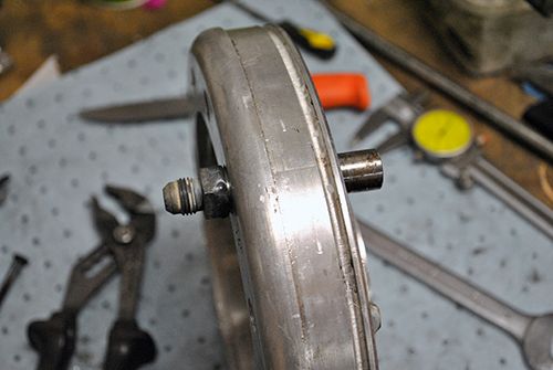 A bit more work on the mill and lathe and the oil pressure tube is ready to have the internal oil line welded to it. 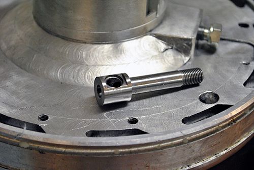 Everything set for tig welding! 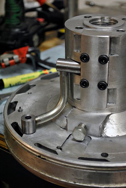 The oil line is cooling down after welding. 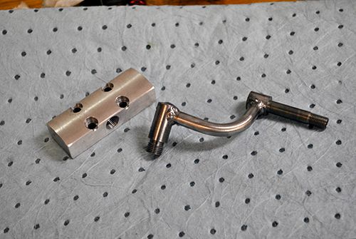 With that done I milled O-ring seats in the distribution block, the silicone rings were bought on Ebay for 1/20 of what a local dealer would charge me... 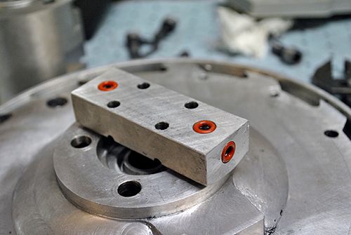 The insex heads were drilled for lock wire, don´t want them to come loose and drop into the turbine wheel. 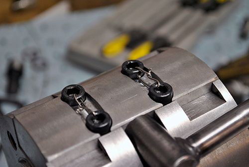 Now it was time to fix the oil leak in the compressor housing, a piston ring seal on the turbine shaft is meant to hold the oil inside the shaft tunnel but during the mishap last winter when the compressor wheel came loose the piston ring sealing surface in the aluminum housing was damaged and started to leak oil. 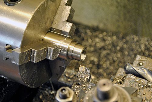 I made a bushing in stainless that the rings will seal against, another benefit with this is that I could make it long enough for both piston rings. Earlier I could only use one ring due to space restraints. 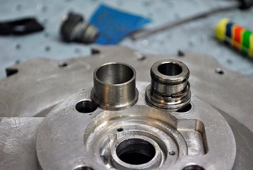 I opened up the hole in the compressor housing so the stainless bushing could be pressed in place. 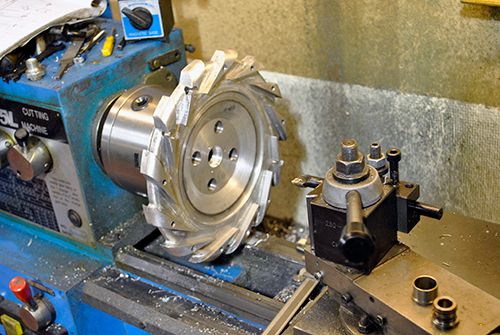 To make sure it wouldn´t spin or drop out I milled two recesses in the compressor housing and grinded two slots in the stainless bushing, a pair of punch marks locked it firmly in place. 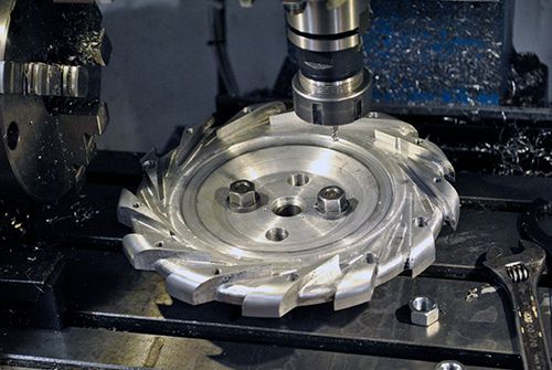 Like this. 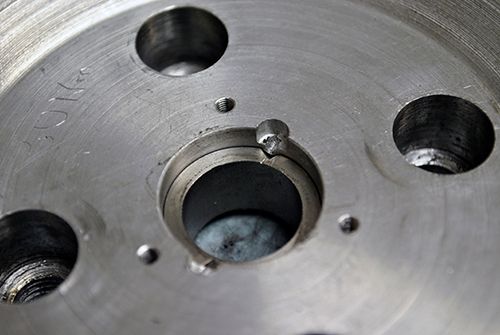 The oil hole for the thrust bearing was then drilled, very important that it is perfectly centered against the O-ring to avoid oil leaks. 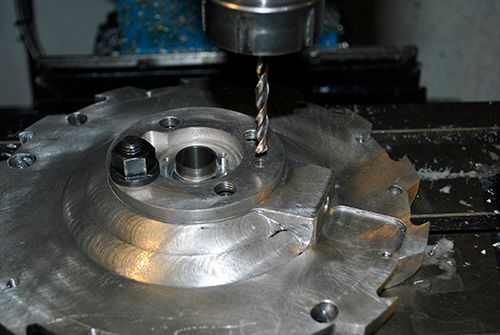 Finally I could start to assemble the engine again, you can see a plug fitted where the old banjo oil fitting used to be. 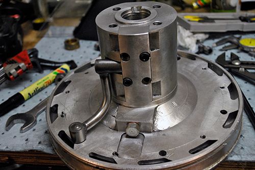 Bearings and oil scavenge line fitted, by now I was pretty hungry so I called it a night and went inside to try to find me something to eat. 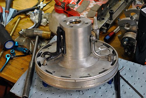 Cheers! /Anders |
|
|
|
Post by turbochris on Sept 22, 2013 11:53:43 GMT -5
gonna have to ride it soon he he he he me thinks it will hold up really well.
|
|
|
|
Post by Johansson on Sept 22, 2013 12:38:46 GMT -5
No riding until next summer I am afraid, the roads are cold and wet all day long now so I don´t want to risk anything. I´ve got a bunch of stuff left to do before I can ride it as well so I won´t make it before snow falls. Today I got up early and headed out to the workshop with a pan of coffee. I forgot to test if the new oil block is leak free so I removed it from the shaft tunnel, blocked off the exits and gave it 5 kg oil pressure. Not a sign of a leak so I am satisfied. =) 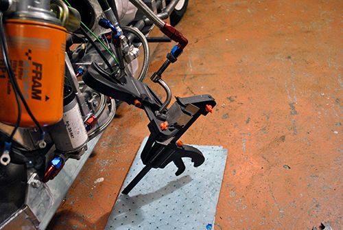 While I had the piece removed I milled the wire lock grooves a bit wider so I could lock the bolts properly. 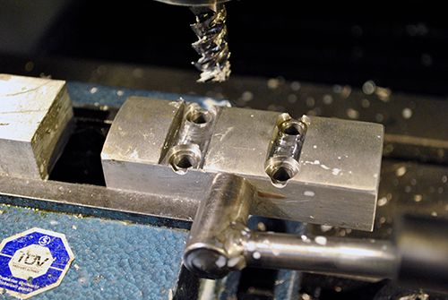 Assembling the shaft tunnel and diffuser housing. 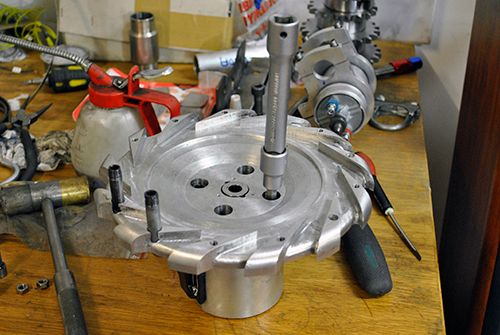 This is what the new wire locking looks like, a bit better than before. =) 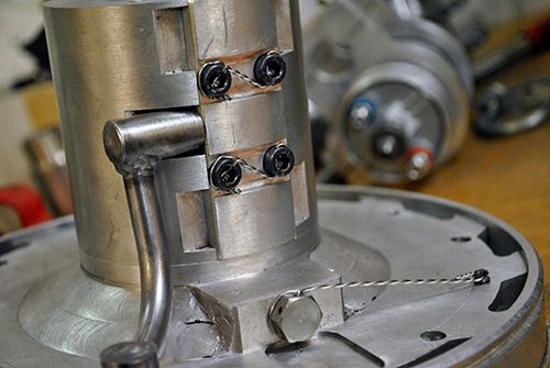 After that I could fit the combustor/NGV piece, the cheramic coating holds up remarkably well despite being exposed to close to 1000°C during some of the early runs. 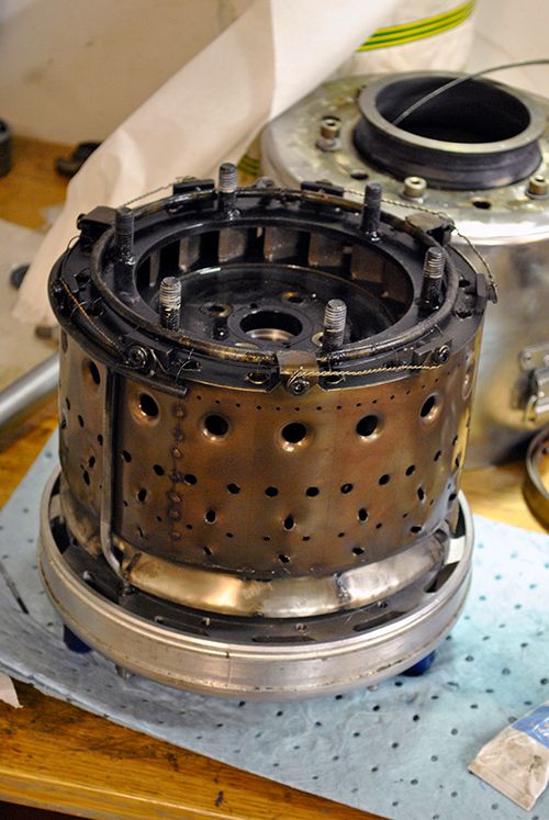 I test flowed the syringe injectors to see if any of them were blocked by dirt in the fuel system, as far as I could tell all of them were flowing fuel so it is all good. 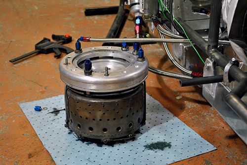 Turbine shaft fitted and compressor wheel on its way! 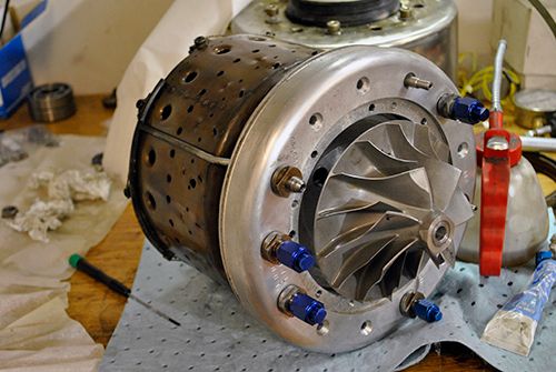 The compressor nut is angle torqued to 130°-145°, feels insanely much but that is according to the manual so it must be correct. 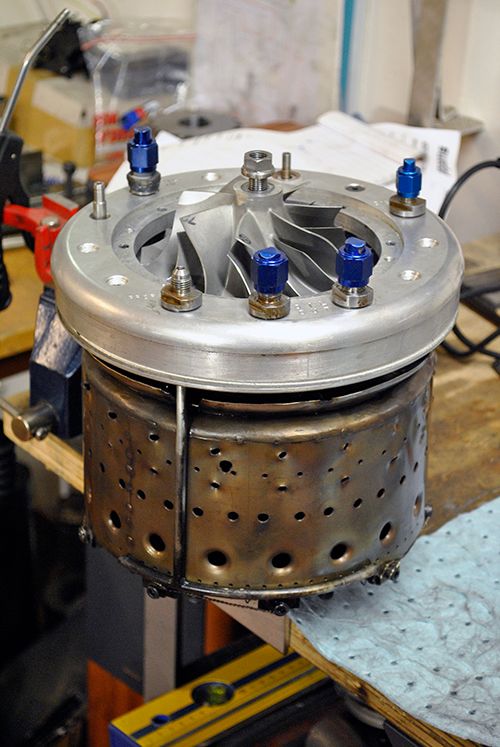 After some more assembling the JU-01 was completed and waiting to be put back in the frame where it belongs. 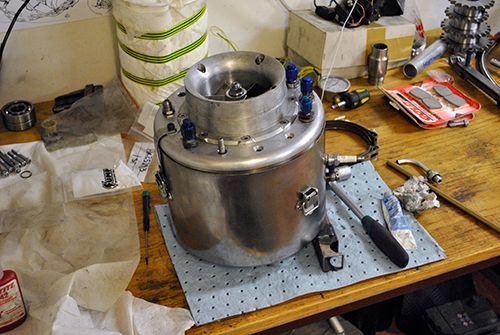 Cheers! /Anders |
|
|
|
Post by stoffe64 on Sept 22, 2013 12:52:35 GMT -5
looks very nice Anders,cant wait to see it run again!
cheers stephan
|
|