|
|
Post by racket on Jul 3, 2015 17:36:37 GMT -5
Hi Chris Having some primary air holes blowing across the evaporator outlets has been used in a number of micro engines without problems , as well as my DIY type engines , though for my micro type engines I have the outer wall primary holes between the evaps jetandturbineowners.proboards.com/attachment/download/7 ,but "modified" to produce swirl across the end of the evaporator , which should have produced a problem if your assumption of flame holding on the downwind side was correct , as Patty was having what appeared to be delayed combustion , and as he's using a thick wall for the combustor which would have made swirl producing hole shapes rather difficult , I felt a hole blowing radially through the outflow might just speed things up a bit , and as that positioning didn't produce problems for me in my DIY engines it shouldn't in Patty's engine. One of Patty's evaporators has been burnt back to almost the secondary holes , its primary hole would be so far away as to not affect the situation , ..............why aren't all of his evaporator outlets burnt if those primary holes are poorly positioned , ................I feel theres an inconsistency with fuel delivery into some of those overly long evaporators which is exacerbated by the use of his particular gasious fuel , there may not be any problems if using liquid fuel injected via a fuel manifold with injectors flowing within plus or minus 5% of average flow . Obtaining equal flows isn't easy even when using syringe needles , looking at my FM-1 journal for August 2006 , I did a number of flow tests to verify consistency of flows , I found I had to replace a number of injectors to obtain relatively equal flows , and I was very careful about consistent manufacture and fitting/positioning of the injectors into the fuel manifold. Cheers John |
|
|
|
Post by finiteparts on Jul 3, 2015 21:52:07 GMT -5
Hi Patty and John, It should be remembered that the air jets serve multiple functions. One, to supply additional air for completing the combustion process. Two, to promote mixing within the chamber and three, to create a stabilizing region for the flame to anchor. I am having trouble understanding how this configuration creates a stable region for flame anchoring. John, looking at your combustor, I highly doubt that you're producing any substantial tangential flow from those holes, and likely they don't ever get the jet to impinge on the vaporizer discharge. The length to diameter (l/d) ratio of that hole is so low due to it being in sheet metal that the hole can't produce any real flow guidance. So I don't think that you can really compare the two combustors accurately. Now some of the small r/c combustors do use that technique, but with a tube so that they get a higher l/d ratio and can actually guide the flow.  The angular momentum provided by the multiple jets sets up a bulk swirl in the chamber that aids the mixing and the stabilization. On the ones I have, you can see a marked difference in the heat marks on the downstream side of the vaporizer tube. Additionally, the tangential jets are farther away (about 0.6 inch) from the vaporizer discharge as compared to the outer liner(~ 0.15 inch), giving more time for the jet momentum to diminish. From the carbon deposits on the dome plate, it can be seen that the tangential jet is not strong enough to interrupt the vaporizer jet, only nudge it. If you look at Rolls Royce's vaporizers (since they do have a ton of experience, in 1971 they claimed over 12 million flight hours!), they are trying to set up a vortex stabilization with their hooked vaporizers and plugs. Notice that the plug flows are not in plane with the vaporizer exit. The plug flows and the liner holes produce the bulk flow in the chamber that supports the vortex stabilization of the flame. The bulk flow strengthen the stabilizing vortex, which is the prime means of flame stabilization in almost any combustor arrangement.  The existence of a small secondary vortex can be seen on the inner liner side of the combustor.  The T-62 uses tangential flows at the inner and outer liner to strengthen the dual vortex formed by the vaporizer discharge flow. The small holes that discharge through the dome plate are placed so that they don't align to the vaporizer discharge.  If I look at the heat staining on the T-62 combustor that I have, I can see the only "cool" region of the dome plate is right where the vaporizer discharge impinges on it. This correlates to what they state in the Rolls Royce vaporizer research. They state that you can't get a long enough vaporizer to fully vaporize all the liquid fuel...so in essence, the vaporizer is really a form of airblast atomizer! That is why they could make their vaporizers shorter and shorter with no effect on efficiency. They also mitered their hooks because the turbulence created by the mitered joints help spread the liquid fuel over the entire inner surface and cooled the metal. So, to your point, why only are only a few damaged? Perhaps those tubes do have lower airflows due to some upstream blockage and thus the impinging jet has more momentum and overcomes the vaporizer jet. They may have uneven fuel flows, but that doesn't explain why the burning appears to be worse on the surface facing the centerline. There is a lot that could be causing this, but the basic need to produce a good flame anchoring mechanism in the combustor has to be considered. This arrangement just doesn't seem to have a coherent flame stabilization scheme. I agree that equal flows are critical...both on the air side and the fuel side. Good luck! Chris |
|
|
|
Post by finiteparts on Jul 3, 2015 22:22:21 GMT -5
Oh, another quick clarifying comment...
John you said, "Temperatures have "nothing" to do with holes, temperatures are caused by backpressure and component efficiencies along with ambient conditions."
That is not true. Your combustor liner hole sizing controls a large portion of the total pressure loss through the combustion system, thus a portion of the system's backpressure. Hole sizing and placement controls:
- your combustor efficiency - lower component efficiencies means more fuel to meet the systems requirements since it directly hits the cycle
- your distribution of the discharge temperature (pattern factor) - could have a hot streak
- where your peak temperatures occur - could be late burning and thus still reacting in the NGVs or turbine.
Everything downstream of the compressor sets the backpressure that the compressor feels. The hole sizing is a balance, trying to get enough pressure drop to get adequate mixing, while trying to minimize the generation of entropy through these same mixing processes. The total pressure loss is a direct hit on the cycle's ability to do work. For a given amount of work (compressor flow and pressure ratio), the total pressure loss translates directly into higher turbine entry temps.
~ Chris
|
|
|
|
Post by racket on Jul 3, 2015 23:47:47 GMT -5
Hi Chris
It looks like you can take over on this, I've run out of ideas "trying to make two wrongs into a right" .
Unless Patty provides detailed data and drawings its just a guess as to whats required to fix problems.
In the case of my comments about temperatures having nothing to do with holes I was referring to Pattys specific holes and arrangements which should not have produced higher temperatures without something else causing them , they are quite adequate for the job if the engine is constructed with due care to providing equalisation of fuel and air flows ............I do not like to overcomplicate an issue by adding more information than is necessary.
Patty is all yours, I wish you luck :-)
Cheers
John
|
|
|
|
Post by finiteparts on Jul 5, 2015 11:35:03 GMT -5
Hi John,
I hope you didn't take my comments as a personal attack on your ideas. Your response appears as if I offended you. I was only trying to provide clear information with a different viewpoint for the site users. The back and forth with information and ideas is what makes this forum so great. New builders can get all kinds of insight by visiting here and seeing others experience/comments.
Again, the users on this site look to you for guidance and knowledge, and unclear comments could easily steer people down the wrong path. I was only trying to clear a very muddy point, because your comment was inconsistent with what I was telling Patty.
Finally, I am more than happy to help Patty or anyone on this site in any way I can.
Chris
|
|
|
|
Post by racket on Jul 5, 2015 17:36:49 GMT -5
Hi Chris
No offence taken :-)
I'm really running out of options with Patty's engine , unfortunately Patty is expecting his engine to be performing faultlessly despite its rather basic level of build sophistication due to the limits of available resources.
Theres also the issue of components that I don't consider a good match for such a basic engine , they could be causing erratic air delivery to all, or even various segments, of the combustor .
I've spent at least twice the amount of time on his engine than what would be expected , my thoughts are that he should simply accept the level of performance he currently has and start doing more detailed data collection to check the measured versus the theoreticals.
Cheers
John
|
|
|
|
Post by madpatty on Jul 29, 2015 22:07:13 GMT -5
|
|
|
|
Post by madpatty on Jul 29, 2015 22:09:44 GMT -5
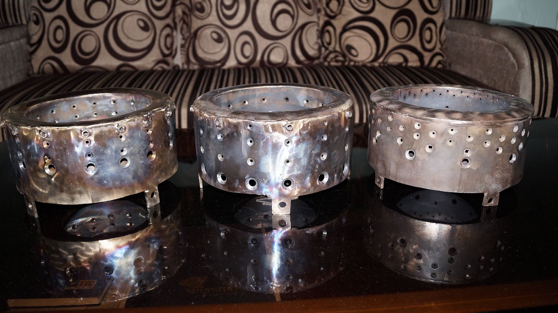
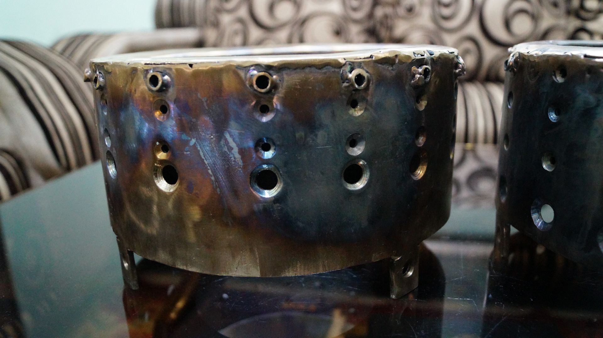
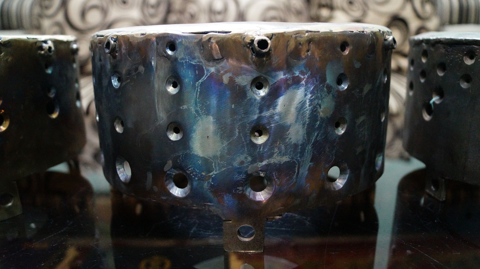
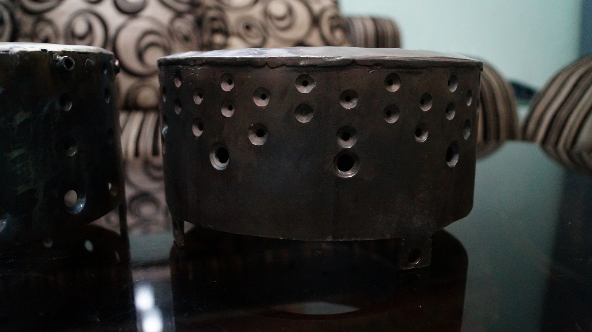
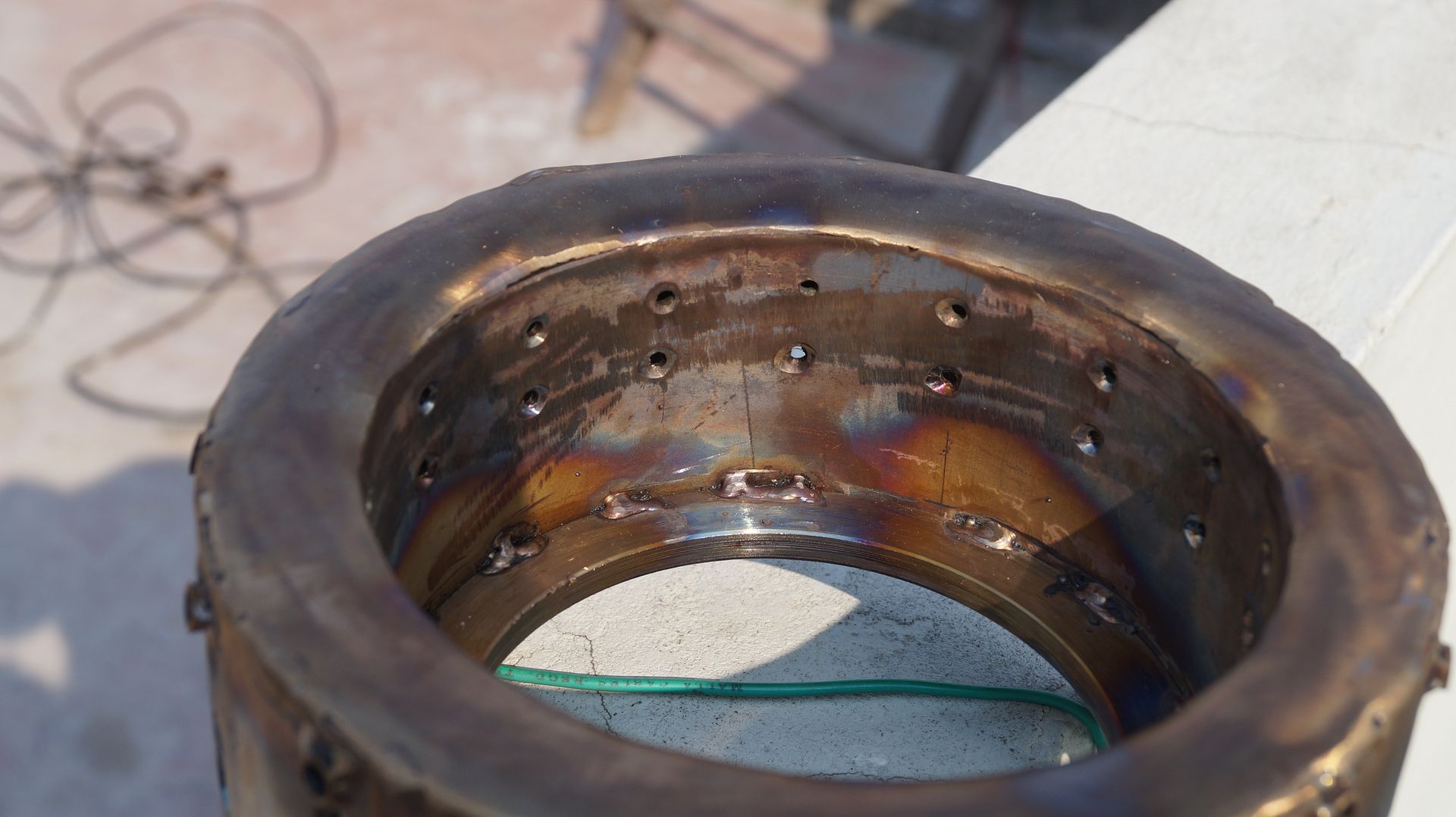
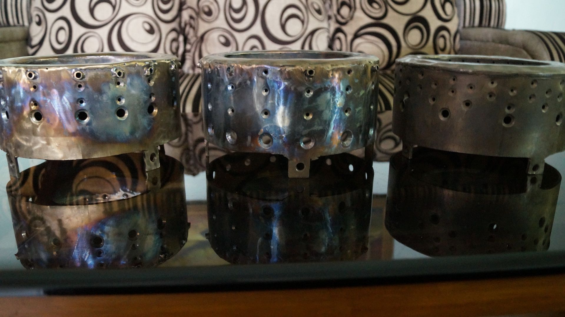
The test run with the latest combustor.
Max P2 of 28+ Psi and TOT of 670 degrees celsius.
Cheers,
Patty
|
|
|
|
Post by racket on Jul 29, 2015 23:25:40 GMT -5
Hi Patty
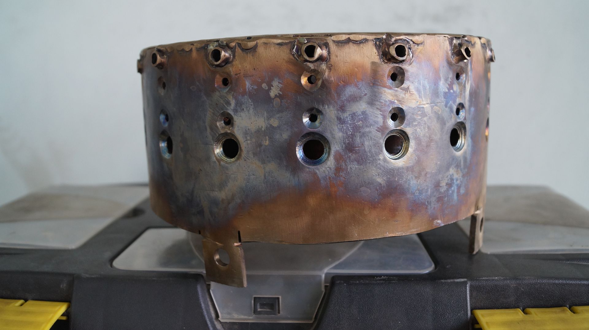
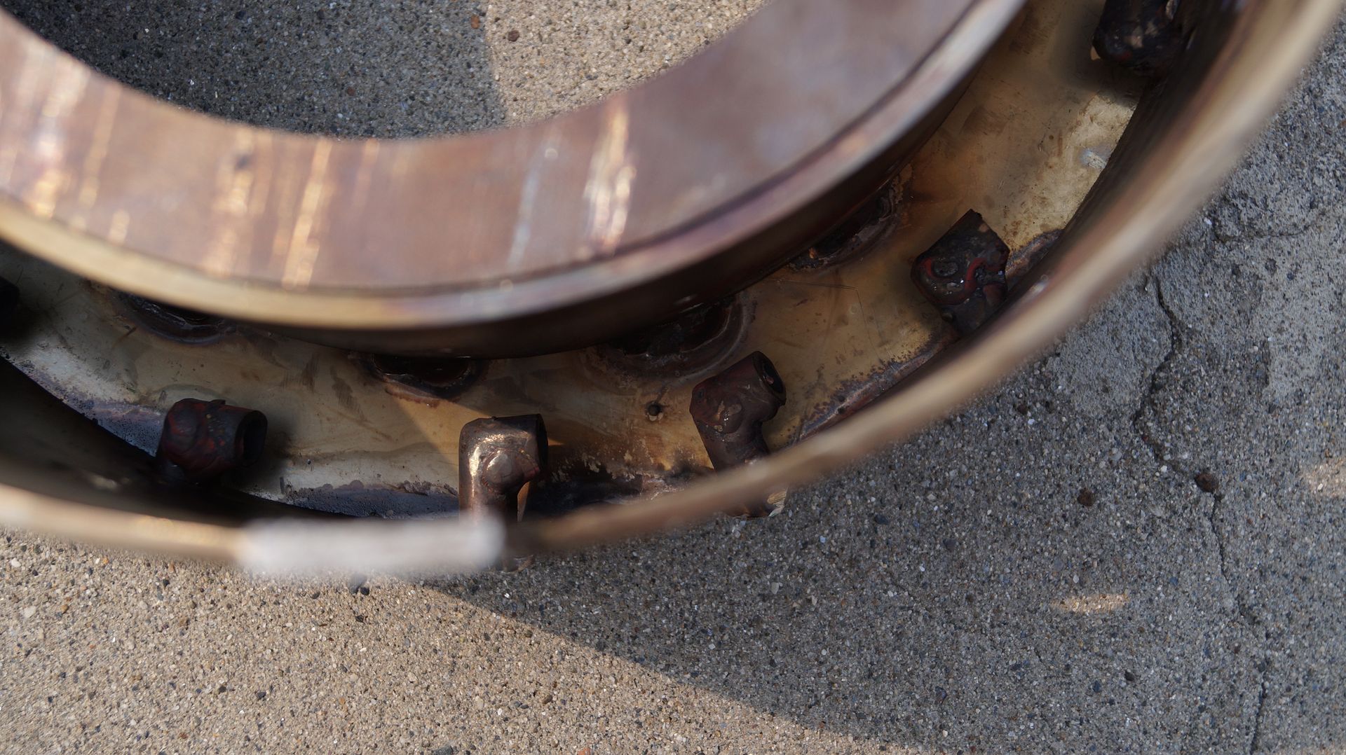
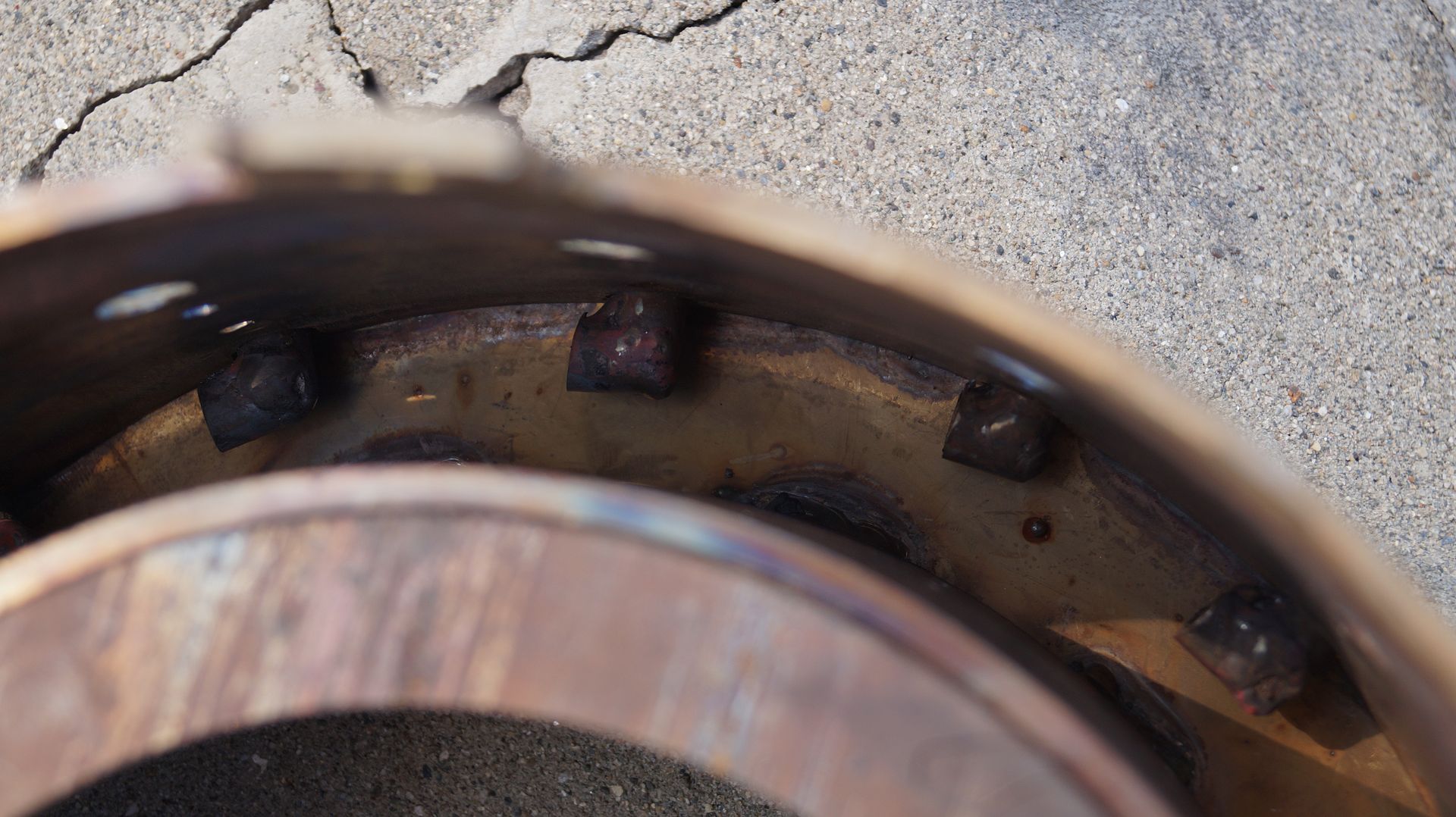
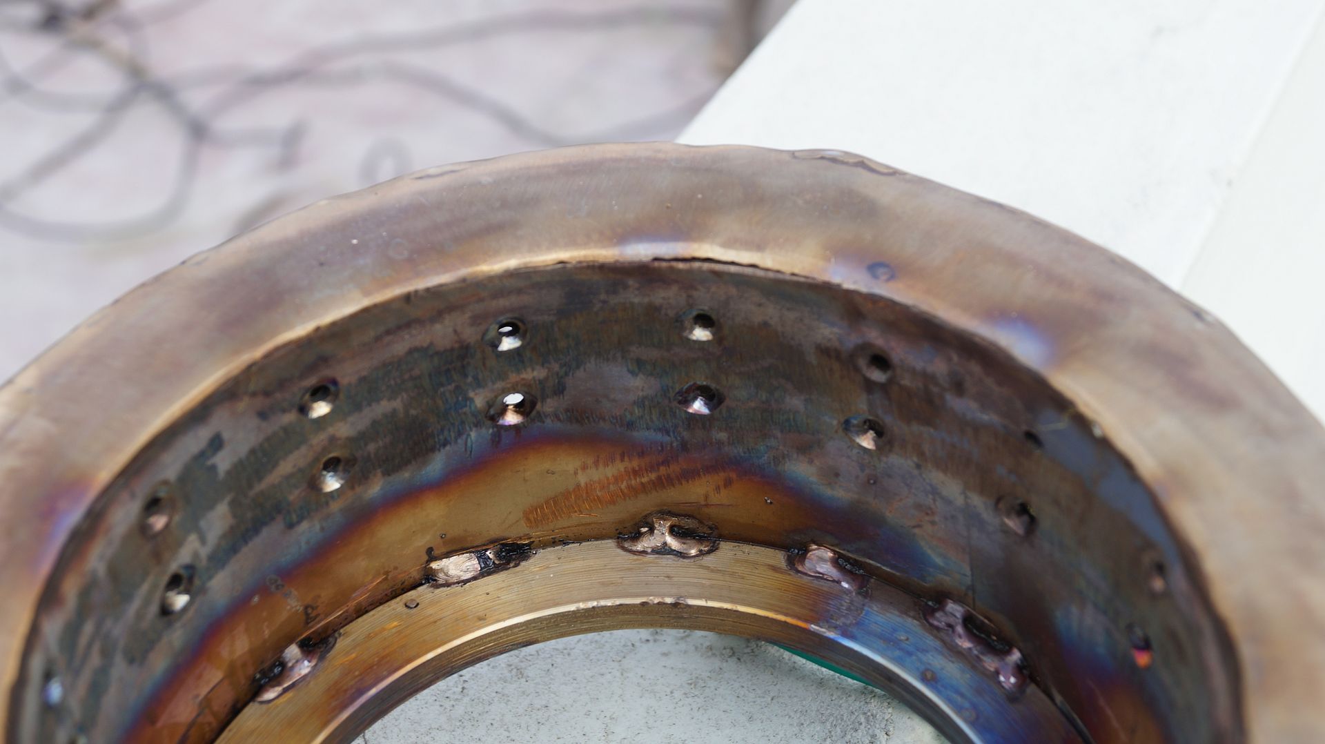
I like your 90 degree primary air swirlers :-)
They'll be adding a lot more air into the primary zone than the original smaller holes .
Is that 670C with a jetnozzle or without one ??
Cheers
John
|
|
|
|
Post by madpatty on Jul 29, 2015 23:29:35 GMT -5
Hi Racket,
670 degrees is with a straight jet pipe measures about 4 inches downstream of the turbine.
Cheets,
Patty
|
|
|
|
Post by racket on Jul 30, 2015 1:27:52 GMT -5
Hi Patty
Thats a bit hot for a straight pipe .
The swirlers appear to be getting more "energy" into the mixing process and evening out the temperatures, but that temp is too high.
Cheers
John
|
|
|
|
Post by madpatty on Oct 7, 2015 10:53:14 GMT -5
Hi Guys,
Can anybody explain the dimensional, power capacity etc. Difference between c18 4th stage and c20 3th stage turbine wheel?
Cheers,
Patty
|
|
|
|
Post by racket on Oct 7, 2015 16:56:04 GMT -5
Hi Patty
The C20 3rd stage has inlet dimensions of 180mm tip, 116mm root , outlet 184mm tip 115.5mm root with a flow area between the outlet of the blade of ~10 square inches , theres a labyrinth tip seal around the wheel , horsepower is probably ~210 hp assuming a 50-50 split of the power production between the two C20 freepower stages.
The C18 has a slightly lower flow and power output so one would assume its 4th stage wheel will be somewhere between the C20's third and fourth stage sizes , I don't think I've got one to measure .
Cheers
John
|
|
|
|
Post by madpatty on Nov 27, 2015 1:52:56 GMT -5
Hi racket and finiteparts, I was just going through some turbine stage related calculations. I have a doubt in some concepts. First we know the design pressure ratio of compressor and its efficiency at that PR and mass flow. Now from that efficiency we calculate the temperature rise across the compressor. From that we calculate the required PR across the turbine stage. What we generally do is;- W(compressor) = 0.99 x W(turbine) Now the doubt is :- The calculated PR is taken across the turbine stage (NGV + rotor) But as we know that rotor is the only power producing component, then the required PR shouldn't be across the rotor only and not complete stage.?? Moreover the Max. TIT we take as the max. Working temperature of turbine material (i.e Inconel) somehwere near 1000 degrees. Shouldnt the Max. TIT be limited by the NGV material and not turbine material as NGV enterance is to encounter the max. Temperature (as temperature has already dropped as flow moves through nozzles) and is almost ~ 100-150 degrees lower than the stage inlet(combustor outlet) temperature?? There must be something very basic i am missing. Cheers, Patty |
|
|
|
Post by finiteparts on Nov 27, 2015 13:08:39 GMT -5
Hi Patty, Good to hear from you again. How's grad school going? These are good questions and it is easy to get a bit confused about the static and total gas conditions. So let's start with the pressure ratio across the turbine stage. If you look at the equation for calculating turbine power, you will see that it is written in terms of total conditions...irrespective of the equations being in terms of total enthalpy, total temperature or total pressures... This concept relates back to the steady state energy equation... Q - W = m(hT2 - hT1) So, across the NGVs, we are converting static enthalpy to kinetic energy...but recall, the total enthalpy is the sum of these two, hT = h + c^2/2 so the total enthalpy does not change across the NGVs. Just as the total temperature and total pressure do not change across the NGVs...ONLY the static temperatures and pressures change across the NGVs. (of course this is for an ideal case with no heat loss or frictional losses...ie, adiabatic and isentropic). If you calculate the work with only the static pressures across the turbine and ignore the NGVs, you will get an incorrect answer since the work extracted by the turbine changes both the static enthalpy and the kinetic energy of the flow through it. If you use the total conditions, then they are the same across the NGVs and thus the pressure ratio across the turbine only is the same as across the stage (assuming there is no losses). I hope that is clear...  It is a tough subject, but absolutely key to master when calculating turbomachinery flow conditions. There is a great course available on MIT's Open CourseWare site that has a ton of great stuff... that might help to clear this up better. ocw.mit.edu/courses/aeronautics-and-astronautics/16-01-unified-engineering-i-ii-iii-iv-fall-2005-spring-2006/thermo-propulsion/The "muddy points" questions from the students are answered by the professor and give some insight. As for the maximum inlet temperatures question...the max use temperature for Inconel 713C is based on the fact that it is used on a rotating part and thus has to maintain a certain level of yield strength at elevated temperatures. If you look at the plot of the yield strength as a function of temperature, you will see that it falls off quickly above 1400F (due to the as cast properties, they are better with post processing steps), thus the usual 1600F TIT design limit is set by a max stress level in the part. You can find that plot here: www.nickelinstitute.org/~/media/Files/TechnicalLiterature/Alloy713C_337_.ashxOther properties are also as valuable, creep, stress rupture, etc...but the yielding curve gives a nice visual indication of the "limit". Now the gas temperatures can go higher than 1600F because the convective heat transfer coefficients are not usually high enough to allow the metal temperatures to fully match the bulk gas temperature, but it is a good, safe operating spot. The NGVs are exposed to higher gas temperatures, but because they are static structural components, they can handle higher temps since they should have lower stresses throughout. That being said, you will often see well used NGVs take on a bowed shaped. Since they are exposed to the gas flow more directly than the hub or shroud walls, they respond quicker to the bulk gas temperature and thus want to grow...but, since the hub and shroud that they are attached to respond slower, thus stay cooler, and do not thermally grow as quickly...the NGVs try to push the hub and shroud walls out, but if the hub and shroud are stiffer, they will resist the NGVs pushing them, which will ultimately lead to the NGVs buckling and yielding in compression, thus bowing the vanes. I hope that helps! Chris |
|


 It is a tough subject, but absolutely key to master when calculating turbomachinery flow conditions.