|
|
Post by racket on Jul 3, 2014 2:35:54 GMT -5
Hi Patty
Sounds good to me .............its a bit strange working with such a small mass flow , everything seems a bit cramped .
Cheers
John
|
|
|
|
Post by madpatty on Jul 3, 2014 2:40:32 GMT -5
Thanks Racket...
So shall i move forward with the above results now?
Thanks,
Patty.
|
|
|
|
Post by madpatty on Jul 3, 2014 3:19:27 GMT -5
Hi Racket,
I am bit doubtful if i calculated the radial area at the diffuser exit correctly....
Firstly i measured the length of arc at the exit then:-
(Lenth of arc x height of wedges x no. of wedges)/sin of wedge angle(20degree)
Is it the correct method??
Moreover what is the permissible value for air velocity outside the flametube??
Thanks,
Patty
|
|
|
|
Post by racket on Jul 3, 2014 4:31:40 GMT -5
Hi Patty
LOL.............air speeds around flametubes , theres probably scientific Papers of several thousand words long on the subject , the easiest solution is copy the Kamps design or scale off it .
One thing that does need checking is your flametube's internal crossectional area , is it at least 3 inducer areas ??
Cheers
John
|
|
|
|
Post by madpatty on Jul 3, 2014 4:43:45 GMT -5
Hi Racket,
The annular cross section area of the flame tube is 733.18mm^2 less than 3 times the inducer area...
Thanks,
Patty
|
|
|
|
Post by racket on Jul 3, 2014 4:50:45 GMT -5
Hi Patty
Mmmmm, thats getting a bit small for burning liquid fuel , you might need to use propane .
Cheers
John
|
|
|
|
Post by madpatty on Jul 3, 2014 5:03:56 GMT -5
Thanks Racket,
But i have to use liquid fuel...
I have no restrictions on the Overall Diameter of the engine so I can increase the outer diameter of flametube keeping the inner diameter of flametube constant....and even increase the diameter of diffuser exit so that annular area between flametube OD and outer walls remains same or atleast does not decrease...
Your views..?
Thanks,
Patty
|
|
|
|
Post by racket on Jul 3, 2014 16:50:51 GMT -5
Hi Patty
If you can increase the OD of the engine by another 15-20 mm you'll be OK , just get that 3 times inducer area for the flametube, then juggle the remaining radial distances to get a nice balance of flow area outside the flametube .
Cheers
John
|
|
|
|
Post by madpatty on Jul 4, 2014 1:51:38 GMT -5
Hi Racket,
The NGV throat area of 1000mm2 is coming out to be a bit greater than the theoratical area of 860mm2.....
How is the practical figure?
Thanks,
Patty
|
|
|
|
Post by madpatty on Jul 4, 2014 3:17:58 GMT -5
This is the NGV section almost ready to be cast in SS304... 12 vanes, 20 degrees to the tangent...throat width is 7.5mm and height 11 mm and vane thickness 4 mm... 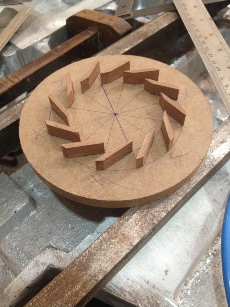 Cheers, Patty |
|
|
|
Post by racket on Jul 4, 2014 3:39:27 GMT -5
Hi Patty
If the throat is too big you'll have trouble getting the design pressure ratio from the comp without high turb temps
Cheers
John
|
|
|
|
Post by madpatty on Jul 4, 2014 4:28:31 GMT -5
Thanks Racket,
It is 140mm2 big...anything can be done with the casting..?
Thanks,
Patty
|
|
|
|
Post by madpatty on Jul 4, 2014 4:44:51 GMT -5
Hi Racket,
What if i reduce the height of vanes from 11 mm to 9 mm so as to decrease the throat area...
OR they have to be equal to turbine inducer tip height(i.e 11 mm)...
Thanks,
Patty
|
|
|
|
Post by racket on Jul 4, 2014 4:52:27 GMT -5
Hi Patty
Throat area has to be correct , how you achieve that is up to you :-)
Cheers
John
|
|
|
|
Post by madpatty on Jul 10, 2014 7:58:45 GMT -5
Hi Racket, Bit of problems here.... I am not able to cut slots in the 10 mm stainless steel plate for NGV due to lack of tools... Moreover Casting also didn result to be of any good...it was very rough piece and moreover of very poor quality... Please comment on the suitability and strength of NGV section if i just weld the NGV on the plate surface without inserting them into slots....  (just place them on the flat plate surface and weld them there)..... Can the job be done this way or inserting into slots is must...? Thanks, Patty |
|


 (just place them on the flat plate surface and weld them there).....