|
|
Post by finiteparts on May 24, 2015 11:08:18 GMT -5
Hi John,
I have that paper in an IMechE book, "7th International Conference on Turbochargers and Turbocharging"...I will give it a read and see what you are referring to. The one thing that I keep coming too, is that I think the mass flows we are calculating as "choked" may be in error...(as per my previous post with the plots of mass flow rate vs expansion ratio). This may change things in your calculations if you assumed ideal 1-d flow.
Alain,
I am glad to see you dug right into that paper! Your observations sound correct...I haven't looked at specific speed vs trim, but your logic sounds correct and as you said, all the calculations point to the same things. I will try to take a look at the trim vs specific speed thing too. Thanks for pointing that out! I have used the specific speed charts to estimate the efficiency, but it was just an extra calculation in the stack to see where I was relative to other geometries out there.
Thanks,
Chris
|
|
|
|
Post by finiteparts on May 25, 2015 22:51:26 GMT -5
John,
I read that paper and I really like how succinctly he described the phenomenon. That was a good paper that I somehow just skipped over...thanks for pointing it out. The funny thing is I have the paper that he references in there in my stack of things to read and still would have missed it.
~ Chris
|
|
|
|
Post by racket on May 29, 2015 1:59:12 GMT -5
Hi Chris
I did some new calcs for my TV94 based engine's NGV and the numbers are interesting .
With a choked NGV throat and gas velocities of 1975 ft/sec and Specific Speed ( Sp/S) of ~1.2 at 70,000 rpm with tip speeds of ~1550 ft/sec , the actual NGV throat area isn't a lot different than when running a Specific Speed of 0.9 , theres less than 10% in the throat areas and only a couple of degrees in the gas angles from the throats.
The get a Sp/S of 0.9 there only needs to be a 1.42 PR across the NGV , this leaves the density considerably higher resulting in the requirement for a much lower "radial" velocity into the wheel keeping the gas angle from the NGV much the same and despite a big reduction in gas absolute velocity from ~1970 to ~1480 ft/sec the throat area hardly changes because of the greater density at the slower speed ...............LOL, its almost as if the system self corrects .
The problems start to arise at the exducer though as theres going to be a need for a lot more swirl ( gas deflection) to compensate for the big reduction in the "impulse" energy .
I workout my turbine wheel's power output requirement from the temperature drop equivalent in gas deflection , then using a "mean" blade speed that takes into account the differences between inducer and exducer "radii" , .................I sorta turb the radial inflow wheel into an axial wheel for the sake of the exercise. ..................its the only way I've been able to "reconcile" the numbers required .
An interesting exercise considering I normally workout my theoretical NGV throat area then add on 10% for boundary layers etc etc , it probably means that my mass flow rate can change a bit to produce the desired Specif Speed and flow angles without overly causing too many problems , I end up with a ballpark set of parameters which are probably good enough for a "backyard" engine :-)
Cheers
John
|
|
|
|
Post by finiteparts on Jul 11, 2015 11:20:24 GMT -5
John,
Sorry I took so long to replied to this...that is good news. I agree, a lot of the processes in the engine tend to "find" their happy place. Many times it may not be the most efficient spot, but more times than not, it is a very operable spot.
~ Chris
|
|
|
|
Post by finiteparts on Jul 11, 2015 12:25:39 GMT -5
I thought I might post some stuff on basic combustor design. The first thing that I wanted to talk about is flame anchoring. There are many means of anchoring the flame, but the one that really dominates the gas turbine combustion world is the swirl stabilization technique. The basic idea behind this is that a strongly swirling flow will produce a region of vortex breakdown that is continually supplied by fresh reactants due to the toroidal vortex flow structure. Additionally, the swirl flow produces strong shear interaction that enhances fuel air mixing. The swirling flow sets up a strong pressure gradient with low static pressure region in the center and causes the outer flow to turn back into the center forming a torodial vortex (like a donut shape). This produces what is called a recirculation "bubble", which forms once a sufficient level of swirl is reached. Increasing the swirl reduced the axial length of the recirculation bubble and increases the shear rate within the bubble, but the pressure loss through the swirl has to increase to drive that swirl flow...so there is a trade-off. You want enough swirl to have a stable, anchored flame wih good mixing, but you don't want to have a huge pressure loss in your combustion system in order to achieve it. A long time ago, I was playing around with radial inflow swirlers. I milled a few slots in a thick washer and tack welded it to a flat plat with a hole drilled in it to make the radial inflow swirler. For the fuel injector, I used a tube in the center of the swirler that had a drilled chamfer at the end to help diffuse the flow slightly (reduce the axial momentum of the fuel flow). The air was introduced through a cone from an electric leaf blower. Here is a video if it running that should help to illustrate the behavior of a swirl stabilized flame and how it anchors to nothing but the low pressure region in the center of the swirling flow. www.youtube.com/watch?v=EMf_ZBZisMEThe "tulip" shape of the flame shows how the flow turns back in on itself and in so doing, it brings in burning products which help to light off the fresh reactants that are flowing in. This is how the flame is stabilized. Due to the rough machining and some inconsistencies, you can see the flame is not fully symmetric. Also, you can see that since I was introducing the fuel axially through the center, if the fuel flow gets to high, I can "blow-off" the flame. If I remade this today, I would inject the fuel radially across the flow to aid in mixing and reduce the propensity of the flame to lift off at high fuel flows. An example of a more consistent swirler arrangement is shown in this video. I used propane as the fuel in a PW2000 liquid fuel injector. The stability of the flame should be quite apparent. Again, the fuel flow rate is an issue on this injector. Because the gas flow momentum can be higher than the airflow in this set-up, the lift off of the flame is apparent. For a liquid fuel, this wouldn't be an issue. www.youtube.com/watch?v=gyt_FHgvMFwFinally, a video I made way back when, shows my senior design project combustor from when I was working on my Bachelor's degree. In this combustor, I had a swirler sized for the primary air requirements (stoichiometric fuel-air ratio) and then a propane injector with 5 radially discharging fuel orifices. For these atmospheric tests, the airflow were lower than what would be produced in the running engine, but it gave a good idea of the basic flow structure and if the swirler was anchoring the flame properly, which it was. But, you can see that with the lower airflow rate, the momentum of the fuel jet was larger than the momentum of the flow entrained in the recirculation bubble and that is why you see the "fingers" of flame. www.youtube.com/watch?v=0wyI5NnM3fgI will add some more to this to show how commercial engines approach the flame anchoring issue that might give people ideas when they are building their own combustors. Enjoy! Chris |
|
ian84
New Member

Joined: July 2015
Posts: 1 
|
Post by ian84 on Jul 13, 2015 6:20:18 GMT -5
Hi All
I am fairly new to all this, but am hoping someone can help as I have been given a jet turbine I believe it is a David Budworth Puffin but can't seem to find out any other info regarding it. What are these things worth and does anyone use them for anything?
|
|
|
|
Post by finiteparts on Jul 14, 2015 20:29:22 GMT -5
Hi Ian, I don't know anything about those engines, but have you looked at the post about that engine?...located here: jetandturbineowners.proboards.com/post/7515/threadI probably speak for many of the others, I think you should post up some pictures of it over on that thread...I would love to see it. Good luck! Chris |
|
|
|
Post by finiteparts on Jul 18, 2015 19:39:36 GMT -5
I have some images of some of the combustors in my collection to illustrate some of the flame stabilization techniques used out there. The first image shows a Rolls Dart combustion can, which uses a 9 flat vaned swirler and well placed primary holes. The primary holes are placed to reinforce the recirculation of the swirler, to create a stable recirculation bubble. The cone on the forward section of the combustor is a secondary diffuser that helps to create a stable air-feed to the outer dome air that dumps between the inner dome cone and the outer combustor liner wall. Notice the welded in cooling strips that direct inward the directed jets both upstream and downstream. This is very unusual and intuitively, it looks like a bad idea to me...but I guess it worked well for Rolls since the Dart was a huge success with many variants. Most of these in later years only worked to "film" the cooling air on the downstream side. The compressor discharge temperature for the Dart was in the 450 F range, so there was a lot of cooling capacity in the air, thus the simple cooling mechanisms could be very effective. 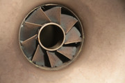 Notice the simple brazed vane assembly. This is very similar to what Rolls also did on many of their combustors. Here is a Spey combustor that shows how things didn't change much (went to 10 vanes at 45) for the swirler between the engines development cycles... 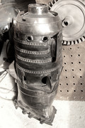   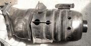 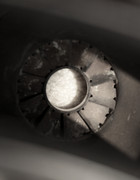 There are a lot of interesting features on the Spey liners. The compressor inlet temperatures for the Spey were higher than the Dart, at something above 850 F, so the liner cooling became more of a concern, since there was less cooling capacity of the air entering. The plunged and cooled secondary jets are very unusual. Notice that they are tubes welded into the liner with a gap on the downstream side. This was done to counter an exhaust smoke issue by pushing the secondary jets through the flare cooling air film coming from the dome. The second wigglestrip between the cross-fire tubes was added to counter an initial liner buckling problem that was partially caused by the wake from the fuel nozzle stem. The wiggle strip cooling, the discharge nozzle splash cooling, the backstop plate and splitters on the dilution holes were adapted from the Avon. The common entry snout feature was pulled from the Conway. Further development of the Spey combustor resulted in the Allison TF-41 combustor, which incorporated a "Transply" or "Lamilloy" liner depending who was talking about it. This one shows one of the big problems with transpiration cooled liners...if they get dirty, they can plug up and overheat. This one appears to have suffered from a leaky injector that plugged the transply with soot and cause a massive thermal fight that resulted in a circumferential crack that almost popped the dome off of this bad boy.  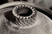 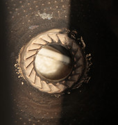 The swirler was modified to a 20 curved vane design because they found the flat vanes would "stall" and thus underflow from the design flowrate and cause a rich primary zone which makes for a smokey engine. They achieved a higher swirl number which increased the mass flow recirculation and not only reduced the smoke, but raised the combustion efficiency. The brazed assembly can be easily seen, which does make it a bit harder for homebuilder to copy, but curved vanes should be easy to do, maybe not in the increased numbers though. The Transply never really caught on... All of these use a primary swirler with well placed secondary holes that strengthen the recirc bubble...this technique has really stood the test of time and is the primary means in the majority of gas turbine combustors, even today. ~ Chris |
|
|
|
Post by finiteparts on Jul 18, 2015 21:16:16 GMT -5
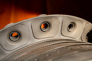
The next combustor is from a Pratt and Whitney engine that I just can't place. It uses an interesting cooling scheme, which looks like a diffusion bonded multi-layer liner. It is a neat sort of tube between sheets kind of cooling arrangement. There are four primary swirlers and the "secondary air enters through eight slots beside each swirler. Notice how narrow the swirlers are. 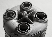  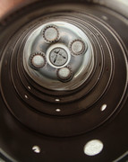 A similar swirler arrangement is on this JT8 variant. The secondary holes are much smaller than other designs, but they appear to be there fr a similar reason, to pump energy into the swirlers recirculation zone. Since these engines operate at much higher pressure ratios, you can see that a lot more detail has been applied to their cooling schemes. 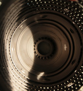 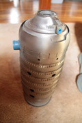 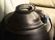 The stacked and welded/brazed rings that form these are pretty easy to do in thin sheet metal and could easily be used by a homebuilder. ~ Chris |
|
|
|
Post by finiteparts on Jul 18, 2015 21:51:48 GMT -5
|
|
|
|
Post by finiteparts on Sept 26, 2015 23:22:14 GMT -5
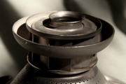
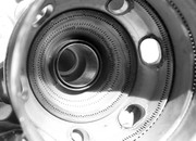
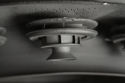
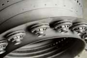
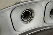
Since the early 1990's, when I first picked up ASME's book "Advanced Centrifugal Compressors" at my college's library, I have read many papers on the high pressure centrifugal compressors that Boeing designed back in the 1960's. They were getting pressure ratios near 10:1 from a single stage with diffuser entrance Mach numbers near 1.3!!! So when I found one on eBay, I jumped at the chance. Now most people will see a dirty piece of machinery...but I hope everyone here sees the beautiful history of high speed flows. The well defined wake regions hanging to the impeller blades suction sides, the secondary flows turning into the wake regions at the impeller discharge, the separated flow on the suction sides of the semi-vaneless regions of the diffuser that persist downstream to the subsonic channel diffusers, the rapid boundary layer growth just after the diffuser throats and the most exciting one of them all...the shadow line of the standing shock in the diffuser throats! (circled) The shock structure in one of their earlier diffusers is shown because that is the image I had in my mind when I hit the "Buy it Now" button! 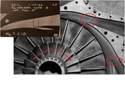 This compressor is from a Boeing 502-11B engine, which has an additional output compressor attached to the power turbine to provide 2.1 lbm/sec of compressed air at a PR of 3.65 when spinning at 36,500 rpm. It was used in start carts. 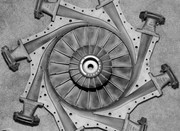
Another shot of the deposit layer formed at the standing shock that forms in the throat. 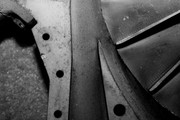
Notice how long the inducer section is...this was done to turn the relative flow into an axial direction as gently as possible, so as to reduce the diffusion upstream and downstream of the inducer throat which helps to keep the entrance flows stable. 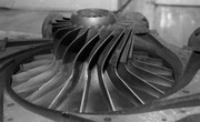
The dirt and staining looks so cool that I struggle with the thought of cleaning it up for display. 
Enjoy! Chris |
|
|
|
Post by racket on Sept 27, 2015 0:05:41 GMT -5
Hi Chris
Now thats a low trim wheel :-)
Looks like ~25 Trim , no worries about inlet shocks .
Cheers
John
|
|
|
|
Post by finiteparts on Oct 4, 2015 13:16:59 GMT -5
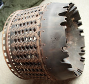
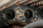
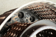
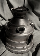
I have been doing a lot of research on vaporizer style combustors recently and couldn't resist picking up an RB199 combustor. For those not familiar with this engine, it is the engine used in the Panavia Tornado produced by Turbo-Union (designed by Rolls Royce and then partnered up with a MTU and Avio to produce it). It incorporates all the standard Rolls vaporizer style combustor elements. The T-vaporizers are something that came out of their work with SNECMA on the Olympus 593 combustor and then later flowed into the F402 and the RB199. Prior to them, they used the mitered hook style vaporizers which were much longer. The lack of a forward cowl diffuser and the rear mounting are some of the claimed key advantages to the vaporizer combustor arrangement. 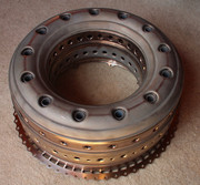 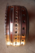 The cooling for the forward section of the T-vaporizer (you can see two of the four holes in the stem base area) and the coating are seen in this view. The cooling holes were later found to be unnecessary in the Olympus 593 engine, but they never got "deleted" from the RB199. 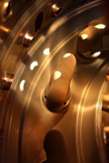
The liberal use of very fine cooling holes is quite apparent...that must have cost a shit ton...maybe even a "metric" shit ton! Look at how they are cooling the downstream side of the primary dilution hole that is plunged into the liner quite deep by today's standards. 
The interior view show just how deep the plunged holes are. They must have worked, Rolls claimed to have very good durability from the vaporizer combustor arrangements. 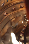
In a paper put out in 1984, they claimed that the reduction of vaporizer length did not hurt performance because the primary mode of fuel preparation in the vaporizers was actually the airblast from the exit lip and subsequent impact to the headend. Coincidentally, the "hot" fuel injector design at that time for low emissions was the airblast. Enjoy! Chris |
|
|
|
Post by finiteparts on Nov 15, 2015 16:58:16 GMT -5
In a previous post I mentioned that often the turbine stage is modeled as a nozzle since you are essentially doing the same thing...converting pressure to kinetic energy. The problem encountered with this modelling approach is that the behavior of real nozzles (or turbines for that matter) is different than what is predicted by the commonly used isentropic relations. The following equation is provided in Hesse and Mumford's "Jet Propulsion for Aerospace Applications"... 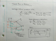 From the T-s or h-s diagram, you can see that because we loose some of the flow's internal energy to friction (thus a gain in entropy), we can't utilize the full pressure drop, since that portion is reserved for the frictional component of the enthalpy (delta_hf). The ideal enthalpy drop through the nozzle is shown in orange, while the enthalpy drop that remains after the frictional losses are removed is shown in green. So how do we use this? Anywhere that you are calculating choking or near choking velocities, you might want to use an estimated value of nozzle efficiency. These areas might be the NGVs, the exhaust nozzle and the turbine throat. Hesse and Mumford give 0.9 to 0.96 as a useful estimate of a "good" nozzle. When you do apply the efficiency factor to a nozzle, the effect is to reduce the velocity through the throat for a given pressure ratio. 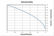 If you look at this another way, it means that you need more pressure ratio to choke the nozzle for a given set of inlet conditions and throat area. As an example, let's say you calculated the choking pressure ratio for: Tin = 1600 F Pambient = 14.7 psia Ratio of specific heats = 1.33 Then you would expect to choke at a pressure ratio of 0.540 as per the isentropic equations...since most of us are more concerned with the upstream pressure and we are not able to vary the downstream pressure, we can invert this ratio and look at the pressure ratio across the nozzle as pt5/p6 = 1.85 So what if we redo that with a nozzle efficiency of 94%, then we get: pt5/p6 = 1.93 and a calculated exit velocity reduced by 3% from the ideal. If we drop down to 90% efficiency, we get; pt5/p6 = 1.994 and a exit velocity reduced by 5.1% from the isentropic values. So you can see that it is easy to accumulate errors due to assuming isentropic conditions and ignoring flow losses... Back to the turbine flow map in question... 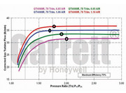
it appears that the smaller scroll housings introduce more flow losses and thus for the purple curve, a nozzle efficiency of 0.9 would well predict the required choking PR. Since the flow velocity is a variable in the mass flow equation, how does this error change the choking mass flow rate? If we assume a 4 in^2 throat, we get: Isentropic Calcs: pt5/p6 = 1.85, choking mass flow rate = 1.252 lbm/s With friction : pt5/p6 = 1.99, choking mass flow rate = 1.349 lbm/s or roughly a 7.7% error in mass flow rate. A final comment on calculations. Often I see that people are using the ISO day ratio of specific heats for air, gamma = 1.4 and this is "ok" for a preliminary calculation, but the ratio of specific heats is a strong function of composition and temperature and can introduce errors if it is assumed constant over the whole cycle. There are tables out there that give the values of air and products of combustion if the highest accuracy is needed. For our purpose, we should be safe assuming that the composition hasn't changed greatly and the specific heat ratio of air at various temperatures is sufficiently accurate. So if we redo the previous equations with the ratio of specific heats equal to 1.4, we get: With friction : pt5/p6 = 2.05, choking mass flow rate = 1.411 lbm/s which is about a 4.6% overshoot in mass flow. I hope this helps everyone make better estimates of their choking mass flows in the expansion end of the engine! Chris |
|
|
|
Post by racket on Nov 15, 2015 20:51:25 GMT -5
Hi Chris
I'm be a bit wary of reading too much into those maps, they're a rough guide to what might happen up to choking point , their main attribute I feel is their actual corrected choked flow from the ~2:1 PR point ,a PR we'll generally all need to use if running the engine up to a decent comp PR .
We might have to assume they're only choking the scroll nozzle and not the whole stage , if the scroll A/R is large enough it'll be the turb wheel exducer that will be the limiting factor .
I can't see how the 1.06 A/R housing can be choking at a lower PR than the scroll A/Rs either side, and at only a 1.7 :1 PR ............very strange .
I use 1.33 and 0.28 for hot gases , 1.40 and 0.24 for air , and once I've calculated the theoretical choked NGV throat , I multiply by 1.1 for "unknowns" , a 10% buffer can easily be accommodated by losses, a bit more comp flow and some extra turb temps if need be ............the actual airflow going through the engine is going to vary in quantity and "quality" depending on so many different factors that I'm not too concerned about getting it entirely theoretically correct because I know it'll always be "ballpark" in those changeable real world running conditions that are the frustration of turbines .
Some of my turb maps have a straight line from 2:1 PR for all the different A/Rs , which sorta tells me that they run choked scrolls with a "large" turbine wheel , whilst the Garrett GT6041 turb map has curves up to ~2.75 PR for both its 1.25 and 1.4 A/R maps which I feel indicates theres a choked scroll and expansion across the turb wheel as well .
LOL........it gets frustrating at times :-(
Cheers
John
|
|