|
|
Post by racket on Oct 4, 2014 4:07:41 GMT -5
Hi Feathers
Yep, the "open" blading ,............. depending on how "tight" the scroll is there might be, or not be , a problem.........a quick check of your T2 temperatures vs your P2 , will give an idea whether or not you are flowing in the middle of the effic. islands or more to the high flow choke side of the map .
What diameter is the exducer ??
Could you post a pic of the turb scroll orientated so that we can look "radially" at the scroll to determine its "thinness or fatness" , the 0.76 A/R you quoted sounds fairly "thin" .
Jetspecs is giving a mass flow rate at ~12 lbs/sq inch/minute of comp inducer , you have a fairly large snout boss on your comp so I cut the flow back a bit to the 1.1 - 1.2 lbs/sec.
Cheers
John
|
|
Feathers
Veteran Member
  
Joined: August 2010
Posts: 169
|
Post by Feathers on Oct 11, 2014 2:35:13 GMT -5
Quick question guys.
So fluid flow through an orifice (like a hole in a flame tube) forms a jet with an effective flow area ("vena contracta") smaller than the geometric area of the hole.
In lots of combustion liner designs, a dimple die was used to flare these larger secondary and tertiary holes in order to improve flow, and better control the effective flow area of the holes.
We've been searching the internet, and can't find any info on this phenomenon outside of incompressible fluid mechanics and the related flow separation.
How does the "radius" of the effective flow area relate to the area of a non-flared hole?
|
|
|
|
Post by racket on Oct 11, 2014 3:20:54 GMT -5
Hi Feathers
A plain hole flows ~64% compared to a similar sized hole with a bellmouth, so radius of the effective flow area is ~0.8 of the actual wall hole ............I think that makes sense .
Cheers
John
|
|
Feathers
Veteran Member
  
Joined: August 2010
Posts: 169
|
Post by Feathers on Oct 11, 2014 3:26:35 GMT -5
That makes sense. So, if a sufficient flare is applied to the hole, than the inner diameter of the flare is "approximately" equal to the effective flow area?
The larger holes will be flared, making their smallest geometric cross-sectional area roughly equal to the effective flow area.
The smaller holes will not be flared, making their effective flow area roughly 80% of their geometric cross-sectional area.
My question is, should these "corrected" (100% area of larger, flared holes; 80% area of smaller, plain holes) areas add up exactly to the compressor inducer area?
|
|
|
|
Post by racket on Oct 11, 2014 5:10:35 GMT -5
Hi Feathers
Yep a bellmouthed/plunged hole can be assumed to be flowing at its full area , whereas the plain holes will only be flowing at ~2/3rds , so technically you either need another half a plain hole for each of those plain holes or the easiest way is simply to make the plain holes a tad bigger in diameter than theoretically required to get your 30-20-50% split for Primary, Secondary and Tertiary Zone , just don't use a multitude of small holes as all they do is cool the wall, we need reasonably sized holes to produce the required penetration into the flametube centre , but we need a reasonable number of holes to effectively cover the cross section of the flametube to produce the required turbulence.
If bellmouthing a hole , you might need to drill it undersized as the bellmouthing often stretches the metal making the hole bigger , its the finished size that counts/matters.
To answer your question , yes the hole area needs to roughly equal the inducer area , but no need to be pedantic about it , theres going to be a heap of other considerations that can/will impact on whether the area is right or wrong ...........we aim for "ball park" to get the engine going then you can fine tune if need be .
Cheers
John
|
|
Feathers
Veteran Member
  
Joined: August 2010
Posts: 169
|
Post by Feathers on Oct 11, 2014 6:09:52 GMT -5
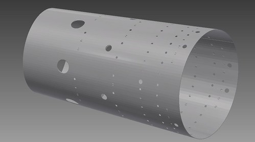
 Capture Capture by HighVoltageFeathers, on Flickr This liner is 10" long, with a 5.5" major diameter (primary end) and a 4.5" minor diameter (dilution zone). I decided to taper the tube to allow greater impingement and turbulence through the tertiary mixing zone, hoping to homogenize gas temperatures more quickly. The total flow diameter follows the 30-20-50 split, with 1.2 times the total compressor inducer area as effective flow area. This is accounting for evap tubes, wall-cooling holes, etc. Disregard the "filled in" wall cooling holes, my CAD software is being ridiculous. How does it look proportion-wise? Thanks for the tips! |
|
|
|
Post by racket on Oct 12, 2014 19:04:59 GMT -5
Hi Feathers
Yep , that should do the job as long as you fit a nice "funnel" to the outflow end to gently guide the gases in their passage from the round flametube to the rectangular turb scroll inlet .
Is there going to be 3 evaporators ??
Cheers
John
|
|
Feathers
Veteran Member
  
Joined: August 2010
Posts: 169
|
Post by Feathers on Oct 12, 2014 23:35:47 GMT -5
We do plan on running three evaporators. Is that too few for a uniform burn?
|
|
|
|
Post by racket on Oct 13, 2014 3:29:18 GMT -5
Hi Feathers
Three could be a bit limiting , best to draw it up to see how it looks , it will leave some "gaps" in coverage of the flametube cross section .
You'll need to consider the actual construction/dimensions of the evaporators as well, and how/if they can be fitted into the available area , with only a 5.5" diameter , 2.75" radius , by the time you leave a bit of clearance between evap and inner wall theres not going to be much of a radial leg on the evap .
I think I'd go to 4 evaps that way the tube diameter can be a tad less to get the required flow area , whilst surface area will go up meaning less "leg lengths" required , yep , play with various dimensions to see what "looks best"
Cheers
John
|
|
Feathers
Veteran Member
  
Joined: August 2010
Posts: 169
|
Post by Feathers on Oct 15, 2014 21:25:18 GMT -5
|
|
ashpowers
Veteran Member
  
Joined: February 2011
Posts: 207
|
Post by ashpowers on Oct 16, 2014 2:18:50 GMT -5
The great part of building combustors for a turbocharger configuration is that the location of the air feed into the combustion chamber can be placed closer to the turbine housing inlet so as to bias the flow in such a way that makes it much easier to produce stable combustion within the primary and secondary zone. The air has to travel upwards, away from the turbine housing inlet in order to reach the primary and secondary zone which results in a lot lower gas velocities within these areas. In my experience I've found that this type of layout is far more forgiving in the design of the combustion chamber as compared to a combustor that receives all of its its incoming air at the combustor "head" first and progressing axially along its length. It almost takes more work to screw up this kind of design, lol.  The only issue I faced is actually having the combustion occur too high up in the chamber and resulting in the chamber lid getting so hot it began to glow. You may want to add in more ports to the plate that the evaporators are attached to in the area where the evap tubes "fire" at to prevent the combustion from burning up that piece. Place the holes just slightly inward, radially, and drill them with a slight angle pointing towards the wall of the flame tube so that the gases will roll outwards. The second upper row of small ports in the flame tube should be staggered between the holes in the top row and they should be shaped as small velocity stacks to project the flow deeper into the combustor. This will blow some of the hot combustion gases back at the evap tubes so they can work properly. Also, the entry of the vaporizer tubes need to be able to ingest air as well as fuel. Hard to see in your drawings where the entry point of the evaporators resides.. It almost looks like they will come up and through the top cap plate of the combustor's outer casing. Do you have drawings to show how all of these parts look when completely assembled? with a transparent view through the outer casing and flame tube so as to see the positioning of everything once assembled? |
|
Feathers
Veteran Member
  
Joined: August 2010
Posts: 169
|
Post by Feathers on Oct 27, 2014 23:57:41 GMT -5
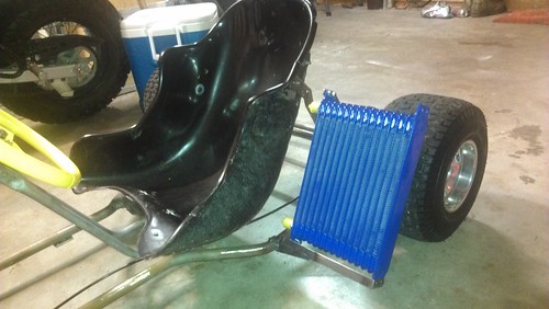
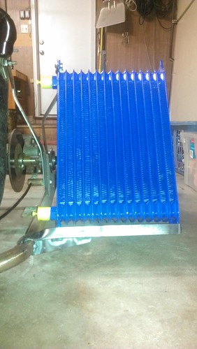
Little bit of progress... Still trying to track down a good VT-50 turbocharger. We've broken two so far trying to separate the core from the turbine scroll. Ended up cutting them apart to salvage the rotating assemblies, seals, bearings, etc. We've got an oil cooler mounted to the kart frame. Just working with what we've got. 
 |
|
|
|
Post by racket on Oct 28, 2014 3:17:50 GMT -5
Hi Feathers
That looks a good spot for the oil cooler ;-)
Cheers
John
|
|
mitch
Senior Member
  
Joined: August 2014
Posts: 285 
|
Post by mitch on Dec 1, 2014 19:15:28 GMT -5
Feathers, the build looks awesome and I like the idea. Quick question in regards to your evaporator assembly. What length will your evaporator assembly's main tube be? (the tube that the nozzle/ injector is positioned in)
|
|
Feathers
Veteran Member
  
Joined: August 2010
Posts: 169
|
Post by Feathers on Dec 2, 2014 15:07:45 GMT -5
Feathers, the build looks awesome and I like the idea. Quick question in regards to your evaporator assembly. What length will your evaporator assembly's main tube be? (the tube that the nozzle/ injector is positioned in) We'll be using Mr. Racket's technique of four separate evaporators, and four fuel sprays into each evap leg. Each leg will be 5/8" diameter, and around 9" long. |
|