Feathers
Veteran Member
  
Joined: August 2010
Posts: 169
|
Post by Feathers on Dec 6, 2014 19:58:20 GMT -5
Racket, We're using 4 evaporators, which will mean four needles for fuel injection on an engine with a mass flow rate of 1.2 lbs/sec.
We will be using PWM fuel pump speed control to regulate fuel flow, and were wondering what an appropriate needle size would be to maintain a fuel pressure of approximately 60 PSI over combustor pressure.
We would use approximately 1" of needle per injector. We just don't really have any point of comparison as to what a good size would be!
Thanks,
|
|
|
|
Post by racket on Dec 6, 2014 21:36:55 GMT -5
Hi Feathers
OK , 1.2 lbs/sec of air needs ~1.2 lbs/min of fuel , so ~680 ml/min , so 170ml/evap/min .
With an evaporative system theres no need for much fuel pressure other than that required to overcome the air pressure inside the engine , you'll probably find needles with a 0.6mm bore will suffice.
My flow tests on a 20 gauge "yellow" syringe needle, 0.9mm OD X 0.6mm ID X 25mm long flowed 100ml/min with just 5psi pressure , 50ml/m at 3psi and 25ml at 1psi .
Using the 20G needle you'll probably only be needing a max of say 20 psi above P2 pressure , so say 60 psi max fuel pressure , easily handled by an auto EFI pump .
Cheers
John
|
|
|
|
Post by pulsedpropulsion on Dec 9, 2014 22:04:56 GMT -5
Just a quick update! We have received our flame tube and transition cone from the laser cutters and have already begun doing the sheet metal work on them. Unfortunately they decided to close the machine shop before we were finished with the transition  . Anyway, once we have them bent and welded, we are going to bellmouth the holes. It's very strange when the parts end up looking exactly like the CAD files!  20141117_090035 20141117_090035 by PESO Jet Kart, on Flickr 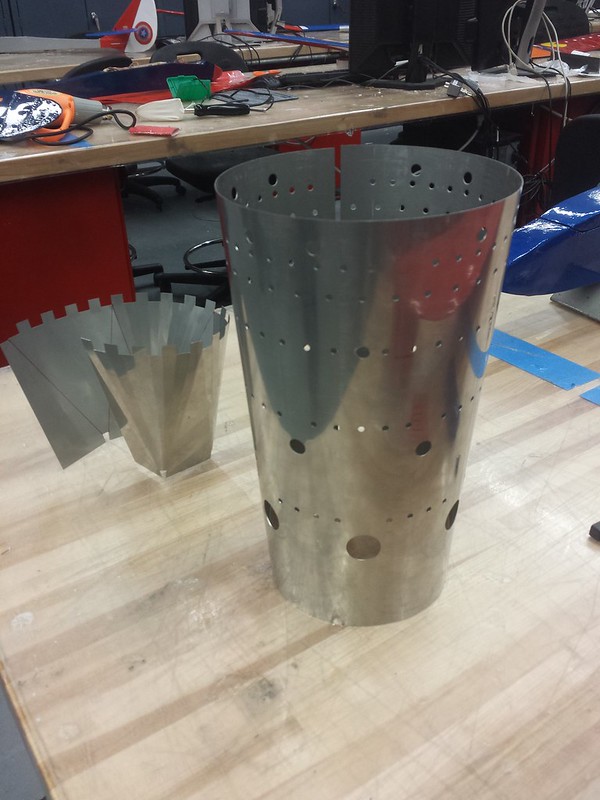 20141209_171650 20141209_171650 by PESO Jet Kart, on Flickr 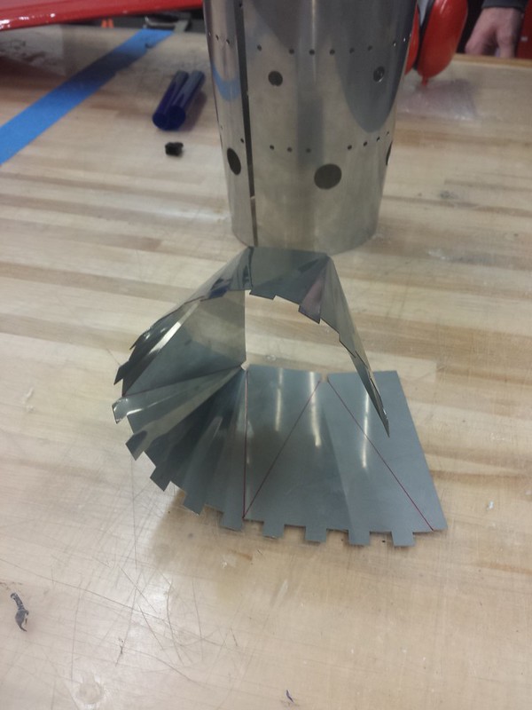 20141209_171735 20141209_171735 by PESO Jet Kart, on Flickr 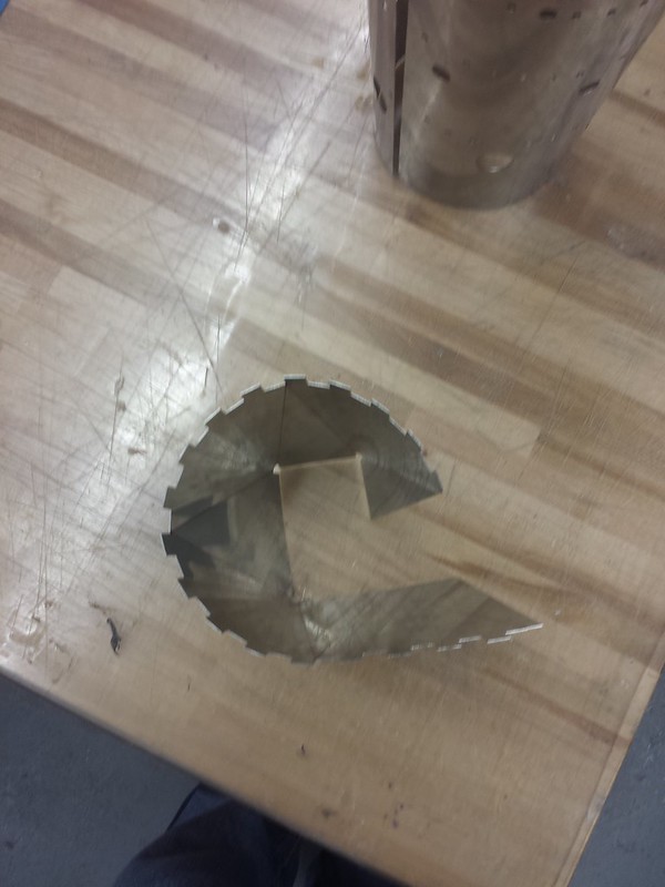 20141209_171740 20141209_171740 by PESO Jet Kart, on Flickr |
|
|
|
Post by racket on Dec 10, 2014 1:55:27 GMT -5
Very nice :-)
|
|
Feathers
Veteran Member
  
Joined: August 2010
Posts: 169
|
Post by Feathers on Dec 16, 2014 23:41:47 GMT -5
Some progress has been made. The combustor liner has been spot welded. Looking for professional opinions, how does the pattern look? I took very careful care this time to scale some successful hole areas, diameters, and placement to our combustor. The three lowest rings of small holes are "bent" downward, to facilitate the formation of a cooling film. The two upper rings of small holes are bellmouthed to increase the effective flow area. The rest of the holes will be bellmouthed as well, as we gain access to the equipment. The fire extinguisher is 7" in diameter, and the flame tube tapers from 5.5" to 4.5", and then the transition. Total corrected hole area is 120% of the compressor inducer area.   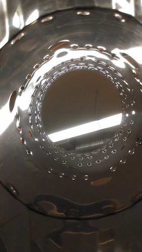 |
|
|
|
Post by racket on Dec 17, 2014 1:05:08 GMT -5
Hi Feathers The holes at the Primary zone might be problematic as they'll be blowing onto the evaporator arms , chilling them in the process . Heres some thoughts I had when making the 2 shaft karts flametube jetandturbineowners.proboards.com/attachment/download/67 The 2 close together holes at the very top ( 1st row) of the sidewall ( 2 X 6mm dia by 4 sets) are positioned so they both blow through the efflux from the evaporator arm , they're positioned just "above" the evap outlet so that their centres are aligned with each edge of the arm tube (3/4" centre -centre ) , I used 2 holes instead of one to hopefully increase turbulence and spreading the air/fuel mix a but wider than if a single larger hole blew straight through the centre of the efflux. The small "plain" 3mm dia holes in the next( 2nd) "part" rows are for wall cooling , their flow won't penetrate far but it will keep the fuel/air mix away from the wall forcing it more towards the centre where it can burn around the longer leg and radial leg . The next ( 3rd) full row of "plain"small holes is for wall cooling The 4th row has both small and larger holes , the "plain" small ones are for wall cooling but the plain unbellmouthed 6mm holes (4 lots of 2) are positioned in the space between evap outlet arms , the holes themselves have had a shallow tapered punch slipped into them and the hole "bent" so that their outflow will be pointing "upwards" and "diagonally" towards the cap of the flametube so that the air jet impacts the combusting fuel vapour as it progresses down the flametube between evap arms, forcing some recirculation back up the flametube towards its centre as well as creating turbulence to aid general combustion . Otherwise I can't see the rest of the FT giving trouble , your current Primary holes may very well work perfectly OK as well , just giving my thoughts in case there is a combustion problem you'll have a possible place to look . A very nice transition piece going into the scroll , are you going to have that as your "slip joint" for axial expansionary movement , possibly up to 8 or 9 mm expansion with a bad hot start , my FT was ~440mm long , with a 800 C temp difference between outer can and FT , there'll be nearly 8mm of expansion :-( Cheers John |
|
Feathers
Veteran Member
  
Joined: August 2010
Posts: 169
|
Post by Feathers on Dec 21, 2014 3:35:50 GMT -5
Thanks Racket. Its no accident that this flame tube looks like the one you used in your kart, we wanted to go with a proven layout. Hopefully the evap tube cooling won't be too big a problem. Otherwise all is well and we're making tools and dies to dimple the larger holes. We'll orient the larger holes in the primary section to impinge on the burning mix leaving the evap system as effectively as possible. Meanwhile, we've been working on prototyping an element of the engine controller, which is the electronic oil pressure regulation. I know that as soon as I say electronic, rather than mechanical regulation, you guys are shaking your heads.  We do however have an electrical engineering student (myself) and an extremely talented software engineer, who has already done some work for Garmin corporation, on our team. We are going to the trouble of an electronic control setup because we want to reduce power consumption as much as possible, for long runs on a battery. Throwing away power with bypass regulation wasn't going to cut it. At the moment the closed-loop control method is extremely basic (coded by myself, and not our more qualified computer engineering student). The microcontroler listens to an oil pressure transducer, and spits out a value. The microcontroller uses pulse-width modulation (PWM) to adjust the speed of the motor. A potentiometer is used to set the position of a "window" of allowable values for the oil pressure. If the measured pressure is above this window, the PWM duty cycle is decremented, and when measured pressure is below this window, it is incremented. This loop is susceptible to oscillations at the moment because the present control method is purely proportional, and the mechanical feedback loop contains an integrating component (expansion of the radiator, lines, and rotational inertia of the pump). But with hotter oil, the latency is reduced and things smooth out. This is an extremely rough setup to see how a proportional control loop responds, but it was an interesting experiment. |
|
Feathers
Veteran Member
  
Joined: August 2010
Posts: 169
|
Post by Feathers on Jan 10, 2015 9:17:38 GMT -5
So we've been making some progress on the "brain" of the jet kart. It will be a FADEC unit, firmware and hardware written, designed, and produced in-house. It consists of three microcontrollers, and a host of IC's and drivers. The first microcontroller is the one you guys are going to worry about.  It will be running closed-loop oil pressure regulation (in a manner similar to in the post above). We're taking every precaution to protect it, and make its operation as solid as possible. It has its own dedicated controller running simple code with coded contingencies for sensor failure, hardware failure, etc. It will be on its own separate, filtered power from the rest of the controller, and will communicate with the rest of the controller in an electrically isolated manner. The pump comes online as soon as the kart is switched on, and the rest of the controller won't operate unless pressure is good. This controller has a "dead-man's pedal" to the rest of the system. It will run the oil pump via PWM speed control with one of the (white) motor driver IC's toward the edge of the board. The second microcontroller will serve as a tachometer, taking pulses from an omron optical sensor and feeding the master controller engine speed, and driving a bar-graph LED display on the steering wheel. The third, large microcontroller will be listening to both smaller controllers, as well as several sensors for access to engine speed, oil pressure, P2, T3, and T4 (via thermocouples and transducers) in order to sequence startup, running, and shutdown based on present engine state, control input, and a set of boundary conditions. This controller will also be in charge of fuel flow, via PWM speed control using the second motor driver IC. It will take input from either a twist-grip, or thumb-throttle with a potentiometer. Of course, there will also be a gigantic emergency stop button controlling power to the non-critical side of the controller. (Oil pressure regulating controller will continue running) Suggestions welcome! 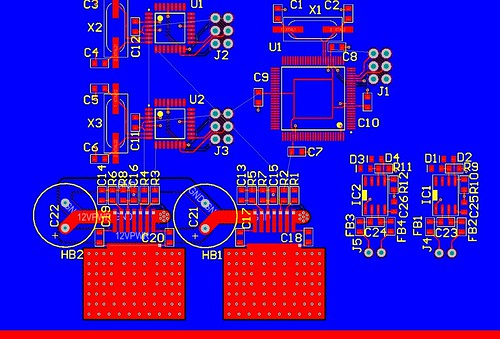 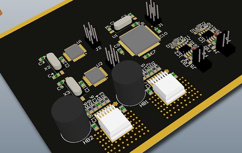 |
|
Feathers
Veteran Member
  
Joined: August 2010
Posts: 169
|
Post by Feathers on Jan 11, 2015 18:40:35 GMT -5
|
|
mitch
Senior Member
  
Joined: August 2014
Posts: 285 
|
Post by mitch on Jan 11, 2015 22:58:35 GMT -5
Feathers, I love your ideas for the FADEC unit for the engine. I myself have been planning an arduino based "ecu" for my engine (once I workout the very large wrinkles in it), but I have limited electronics and programming knowledge, so it will be no where near as well designed as yours. Also I am curious to see how the individual evaporator tubes work in comparison to a single trunk style. Great work here!
|
|
|
|
Post by racket on Jan 12, 2015 1:29:08 GMT -5
Looking good Feathers :-)
|
|
Feathers
Veteran Member
  
Joined: August 2010
Posts: 169
|
Post by Feathers on Feb 9, 2015 13:47:10 GMT -5
Well CRAP. School is in session again. Slowing down slightly, but still moving. Now we have a giant collection of t-50 variants (a t-50, vt-50, and an st-50) in various conditions, and we're trying to mix and match parts. The turbine of one won't fit the scroll of another, one turbine wheel looks better than another, one center housing is a smidge longer than another, one compressor housing has diffuser vanes and a plenum, but experienced a compressor nut failure, ETC.  We'll make it work somehow, and at least all the journal bearing components are interchangeable.  We've cut the flanges that will hold the combustor casing to the turbine inlet. (they're finished now, we just don't have pictures. 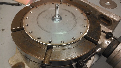 And here are some pictures of the fuel feed-through. Two 1/8 npt couplers will be installed to carry propane and diesel through, and we cut a gland for an 1/8" silicone O-ring. 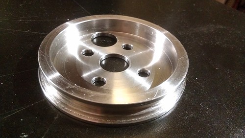  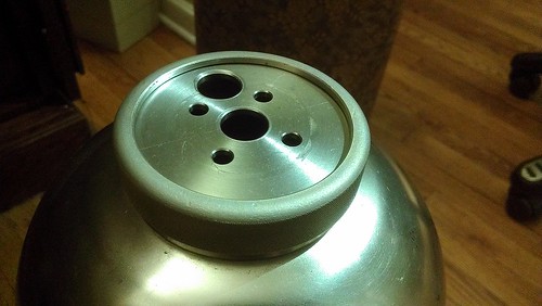 |
|
Feathers
Veteran Member
  
Joined: August 2010
Posts: 169
|
Post by Feathers on Sept 28, 2015 11:49:52 GMT -5
Its been a while!
We were wondering what the main sources for c20 turbine wheels are... Ebay has several, but at prices that would buy me a decent car. Any surplus pages or online resources you guys are using?
The T-50 turbine wheel is just too small to produce much torque, considering the maximum reduction we are restricted to by a direct chain drive.
Do you have any suggestions as to a more suitable "ballpark" turbine wheel? We don't have a running engine yet, but we've got a decent guess as to how it will operate. Our resident aerospace engineering student might chime in as well.
Thanks!
|
|
|
|
Post by Johansson on Sept 28, 2015 11:56:04 GMT -5
Hi Feathers and welcome back!  The decomissioned C20 wheels are sold on Ebay for scrap value from time to time, I payed like 200 dollars for one I found. The 8000 USD wheels being sold still have flight hours left in them and have full documentation, nothing for us DIY:ers.  Keep an eye on this seller, I just bought a C20 4th stage NGV from him. He seems to add stuff all the time, but the information about the items are very limited unfortunately so you need to know what to look for. stores.ebay.com/Dr-Fantom/_i.html?_nkw=turbine&submit=Search&_sid=835865524Cheers! /Anders |
|
|
|
Post by pitciblackscotland on Sept 28, 2015 14:10:33 GMT -5
Hi Feathers, What size turbine wheel are you after? I have some turbine wheels that i can sell to you have a look and let me know. Cheers, Mark.     |
|