|
|
Post by racket on Sept 28, 2015 15:28:01 GMT -5
Hi Mark
I think that "second stage" wheel is a first stage wheel , the second stage wheel has a lot more blades (48 of) and is ~163 mm dia with root dia of ~120mm with a throat "flow area " at ~5.9 sq ins .
A second stage wheel with 5.9 sq ins of throat area might just be big enough for Feathers if his energy levels entering the freepower stage are high enough, but I think I'd suggest the 3rd stage wheel which has more than enough flow area at ~10 sq ins , LOL..........its easier to limit the area going into the 3rd stage wheel than add a bit onto the second stage :-)
Cheers
John
|
|
|
|
Post by pitciblackscotland on Sept 28, 2015 18:17:49 GMT -5
Hi John, Thanks for that i was hoping you would check them out for me  Cheers, Mark. |
|
|
|
Post by racket on Sept 28, 2015 20:33:31 GMT -5
Hi Mark
Heh heh , no worries ;-)
Cheers
John
|
|
Feathers
Veteran Member
  
Joined: August 2010
Posts: 169
|
Post by Feathers on Sept 28, 2015 21:30:16 GMT -5
Wow!
Thanks guys,
Mark, I've PM'd you.
This thing is going to SCREAM.
Updates will be rolling in. Its the school year again, and our school group is firing on all cylinders.
|
|
|
|
Post by smithy1 on Sept 28, 2015 21:52:50 GMT -5
Wow! Thanks guys, Mark, I've PM'd you. This thing is going to SCREAM. Updates will be rolling in. Its the school year again, and our school group is firing on all cylinders. Firing on all cylinders won't help much with your turbine project..  Cheers, Smithy. |
|
|
|
Post by pitciblackscotland on Sept 28, 2015 22:06:13 GMT -5
Hi Feathers and Jonh, Have another wheel this one must be a 3rd stage OD is 190mm 30 blades same as the first wheel i post up, on this wheel the numbers read 6899373-E area 10.08. Cheers, Mark.   |
|
|
|
Post by racket on Sept 28, 2015 23:08:01 GMT -5
Hi Mark
Yep , the 3rd stage wheels have flow areas around that 10 square inches , the tip on the inlet side is ~180mm dia and a tad bigger at 184mm on the outlet , add on the laby seal and its ~190mm , yep, 30 blades .
Cheers
John.
|
|
|
|
Post by pitciblackscotland on Sept 29, 2015 0:20:29 GMT -5
Wow! Thanks guys, Mark, I've PM'd you. This thing is going to SCREAM. Updates will be rolling in. Its the school year again, and our school group is firing on all cylinders. Hi Feathers, have not receive your PM  Cheers, Mark. |
|
Feathers
Veteran Member
  
Joined: August 2010
Posts: 169
|
Post by Feathers on Sept 29, 2015 12:34:28 GMT -5
Hi Feathers, have not receive your PM  Cheers, Mark. Forgot to send it! Sorry about that. PM actually sent. |
|
Feathers
Veteran Member
  
Joined: August 2010
Posts: 169
|
Post by Feathers on Oct 14, 2015 14:25:16 GMT -5
Just to be certain,
Racket, would you suggest we try to work with the first, or third stage wheel that Mark is offering? We're looking for as much torque with limited reduction as possible.
Thanks!
|
|
|
|
Post by racket on Oct 14, 2015 16:29:59 GMT -5
Hi Feathers
You'll be needing the third stage wheel , it'll probably be a tad oversized with regards flow capacity, but thats OK and can be "accommodated" by "adjusting??" the NGV design , but the first stage wheel simply won't have sufficient flow capacity , you'll send your gas producer into surge .
I used a third stage wheel for the freepower with my Garrett TV84 turbo that had a 3.5" inducer.
Its much safer to have an oversized freepower than even a tad undersized one .
Cheers
John
|
|
Feathers
Veteran Member
  
Joined: August 2010
Posts: 169
|
Post by Feathers on Oct 14, 2015 21:13:12 GMT -5
Alrighty, we'll go with the 3rd stage.
What do you think we should do to accommodate a turbine with too much flow?
|
|
|
|
Post by racket on Oct 14, 2015 23:37:36 GMT -5
Hi Feathers
Generally just "tighten up" the NGV throats by "lowering" the angle, there will be more losses as the lower angle generally means more NGV vane area in contact with high speed gases , but I have a NGV from a ALCO locomotive turbo with the vanes at a very low ~10-15 degrees from the plane of the wheel for maximum extraction of power from the diesels exhaust, though a 20 - 30 degree angle is more the norm for aircraft stuff .
Another way is to have partial entry to the wheel rather than the full 360 degree annulus .
With an oversized wheel theres always the opportunity for "augmentation" of the gases exiting the gas producer , water and/or fuel addition in a second combustor to create a greater volume of gas to effectively "fill" the larger wheel passageways.
Once you have the data from your "pure jet" engines jet pipe you'll know what energy will be available for the freepower which can then be designed to suit.
The main thing is the 3rd stage wheel won't cause problems for your gas producer, all that will happen is the gas producer will run cool and your power production will be below expectation , its the right side to be on in the beginning , the last thing you need is a marginally sized freepower that could wreck your gas producer the first time you fired up the combination.
Cheers
John
|
|
Feathers
Veteran Member
  
Joined: August 2010
Posts: 169
|
Post by Feathers on Oct 15, 2015 0:30:21 GMT -5
Sounds great, should be pretty easy to tighten up the NGV. We'll go ahead and get the 3rd stage, and see where our gas producer ends up energy-wise. Augmentation will be fun. We'll have some space between the gas producer turbine and NGVs, so who knows  Thanks for the advice, as always! |
|
Feathers
Veteran Member
  
Joined: August 2010
Posts: 169
|
Post by Feathers on Oct 20, 2015 16:44:02 GMT -5
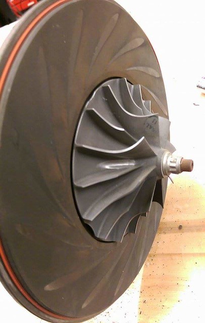
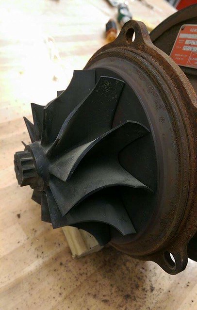
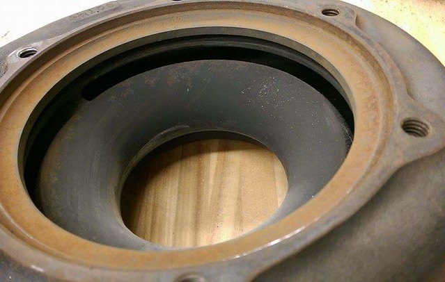
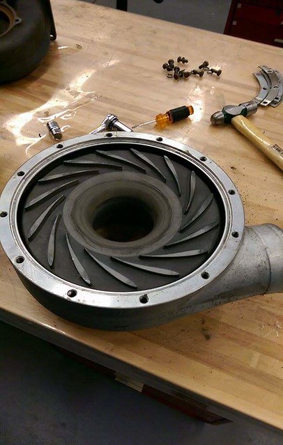
Hey! We've got a good turbo! One of our Aerospace professors gave it to us. Its an old AiResearch turbo, remanufactured by Garrett. Its a T1823 used in Lycoming aircraft engines. Same inducer dia as our old (broken) VT-50 units, same diffuser/plenum style, turbine A/R is close, at 1.09. It /is/ a divided turbine scroll, but the "division" is lopsided, approximately 25/75 area-wise. We can do some careful grinding to open it up as well. Here are some pictures. It "spins" the correct direction for a high-mounted combustor on the kart (it will fit like Racket's). Let us know what you guys think. 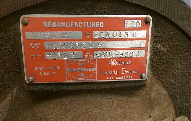
 |
|