paradine
New Member

Joined: September 2014
Posts: 2 
|
Post by paradine on Sept 28, 2014 15:56:48 GMT -5
I had a question regarding the design of a turbine combustion chamber, and more specifically, the shape. I'm currently in a combustion course for my mechanical engineering degree, and have little to no knowledge on turbine combustion chambers, but was asked to figure out the optimal curvature needed in the areas defined by the red circle. This knowledge would be used to make a CAD model, that would then be imported into fluent for simulation and analysis. I have looked up several different turbine combustion chambers online, and some of the options were having a straight line, a parabolic curve, or implementing fillets to the edges of the straight line. ![]() 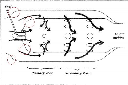 To summarize, I would like to know the basic phenomenon that occurs in these areas, and what type of contour would give the most optimal/efficient combustion. Regards, Brandon |
|
|
|
Post by racket on Sept 28, 2014 16:48:59 GMT -5
Hi Brandon
Combustion takes place within the flametube , "optimal/efficient combustion" will depend more on hole placement , size , shape , fuel spray angle , type of spray , atomisation droplet size ,etc etc etc ..........rather than the curvature of a couple of corners...........they'd be consigned to the bottom of the list , more in the "art" rather than the "science" of combustor construction .
As long as there weren't any sharp corners , the curves would probably have more to do with what was "manufacturable" and pleasing to the eye as far as creating a nice smooth flow, neither diffusing or accelerating flow around the flametube and creating losses .
Combustors fall into an area of design that isn't always "scientific" .
There are Papers written by Lefebvre and Norster
Cheers
John
|
|
paradine
New Member
Joined: September 2014
Posts: 2
|
Post by paradine on Sept 28, 2014 18:06:12 GMT -5
I appreciate the quick response, and you were very helpful!
Regards,
Brandon Sloan
|
|
|
|
Post by finiteparts on Sept 28, 2014 18:15:09 GMT -5
Hey Brandon, That seems like your professor has given you a very poorly posed design problem, in that you are not informed why or for what you are optimizing these regions. My guess would be that you are to design the aft portion of the diffuser to minimize the flow losses as it "dumps" out of the main diffuser region into the combustor head end. One common approach that many aero guys use is to not focus on the shape of the walls, but to focus on how the area is changing in the flow path. You should do everything you can to make the flowpath as smoooth as possible...Sudden jumps in area can induce flow separations and losses...similarly, sudden contractions cause local regions of acceleration that can also cause issues. I would refer you to Arthur Lefebvre's book on the subject, "Gas Turbine Combustion" or A. M. Mellor's book, "Design of Modern Turbine Combustors". More specifically, there is a great paper in Progress in Aerospace Sciences on combustor diffusers, maybe your school gets this journal: Klein, A., "Characteristics of Combustor Diffusers", Progress in Aerospace Sciences, 1995, Vol.31, pp. 171-271. www.sciencedirect.com/science/article/pii/037604219500006KWith the limited "problem statement" it is hard to assume what you are trying to achieve. But the common issues faced by aero-engineers in designing diffusers is to make sure the flow is stable and minimize the losses. Flow stability is an issue because when the flow separates, it usually does so in a unsteady fashion...think of it like a flag flapping, were one side of the flag would be the separated flow from the surface and the other side would be the bulk flow in the diffuser. The minimizing of losses should be pretty apparent...you want to recover as much of the kinetic energy that you put into the fluid with the compressor as possible and turn it into pressure energy. As for "optimizing" the expansion region near the combustor, that sounds like a tall order. Do you have the other portions of the combustor and diffuser already defined as boundary conditions? Good luck! ~ Chris |
|
|
|
Post by racket on Sept 28, 2014 20:22:29 GMT -5
Hi Chris
Totally agree with you about the Prof., ..........heh heh , sounds like he doesn't know a lot about the subject , otherwise he'd know how complex combustors can be , and how a good deal of it wasn't science when that type of multiple can combustor design was in use , and wouldn't ask such a "loose" question ........................Bummer , I think I'd be getting a fail mark for my answers to this one :-(
The drawing/design of the can has some "flaws" in that theres not a "faired" section between the inlet to the swirl vanes and the outer corner of the flametube , theres a potential "dead spot corner" that will disrupt the streamlines , theres a large increase in flow area after the inlet to the swirl vanes followed by a restriction , the original Rolls Royce Dart combustor can ( that this looks like its modelled on) had a much smoother flow passageway due to a fairing.
Mmmmm, I think my only answer would be that the curvatures need to such that the cross sectional flow area needs to be constant , the "included" angle of the corner would be that required to produce the necessary flametube length/diameter ratio within the space between compressor and turbine wheels .............heh heh , lets baffle the Prof with BS ;-)
Cheers
John
|
|


