Post by hendocal on Dec 27, 2016 14:05:16 GMT -5
I'm building a jet engine in the standard micro jet Kamps/Kurtling sort of manner and I've come across a problem.
I have the Thomas Kamps Model Jet Engines (3rd edition) book and it has lots of typos in the equations.... I've figured out what most of them mean but, if you'll excuse the pun, I can't figure out probably the most critical equation, the critical rotational speed equation.
It has this equation for the compressor critical angular velocity:
3 x E x I
ω = Square root of : ---------------------
m x (l+c) x c^2
which is in rad/s so times by 30/pi to get r.p.m.
E=modulus of elasticity of shaft, book says it is 210 x10^-9 for almost all steels
I = (d^4)*Pi/64 where d is the shaft diameter
l = bearing spacing
c = distance from the wheel CG to first bearing
m = wheel mass
There are a few issues.... firstly if I put in the example numbers I get a different answer to the book. Secondly it then says do the same equation respective for the turbine wheel and then use the following equation for the shaft. Only the following equation is just an exact copy of the one for the compressor and turbine. It then lists the variables supposedly used. It lists l, d and rho. Obviously the equation has E, I, m l and c in not l d and rho so that HAS to be wrong.
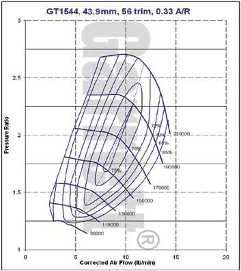
To make things worse, my compressor wheel is only 43.9mm in diameter and so, following the compressor map and the correct thrust calculations I have made, it needs to run up to 200,000rpm. From the bits of poking around I have done online it seems that RPMs much higher than 100k are seen as not safe in the model jet engine builders world.
Any advice on correct equations and whether I will be able to get away with such high rotational speeds would be much appreactied!


