|
|
Post by finiteparts on May 29, 2017 11:33:16 GMT -5
Ok, back to combustor design. I think I will skip right into the calculations and then discuss the theory as we go along. I will be working through the calculations for a can style combustor for my Borg Warner EFR6758 turbos. I gave some of the design point specs on the previous page, but here is a refresher: Liner outside diameter = 5.0 inch
Combustor casing inside diameter = 6.0 inch
Compressor discharge temperature, T3 = 340 F
Compressor discharge pressure, P3 = 47 psia
Pressure drop = 5%The approach that I am using is from Arthur Lefebvre's book, "Gas Turbine Combustion", but I will also shamelessly steal techniques from other books. I highly recommend these books in addition to Lefebvre's book: Aircraft Engine Design, 2nd edition, Jack Mattingly, William Heiser and David Pratt, AIAA Education Series, 2002
Design of Modern Turbine Combustors, A.M. Mellor, Academic Press, 1990
Ok, so I will just start with the basics. Once we have some design point numbers and a target combustor pressure drop, how do we figure out how many holes to put in the liner? I am a strong believer in showing by example....so I will work these out for my combustor and you can just change the relevant data to work your design. Also, I highly recommend that you always check your units! They beat this into you in every engineering class and it really does help to catch errors...so you will see in my calcs how I was taught to check units. First, Lefebvre developed a few reference parameters. The first one is a reference area and it should be noted that it is just the open area inside the combustor casing...we don't have to concern ourselves with the liner size yet. The properties are the compressor discharge temperature and pressure, not the hot gas properties in the liner. This is because what we are basically trying to do is ise the orifice area that produces the required pressure drop across the liner. The hot gases have a pressure loss of their own, called the fundamental pressure loss, which should be very small if the Mach number in the liner is low. We will ignore these for the moment, but may touch back on these later. 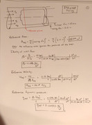 Now that we have the reference properties, we can calculate what is termed the pressure loss factor. The PLF is used to get the effective flow area requirements from the reference area. 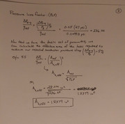 So we now know that we want to end up with a total effective area across all the liner holes and any other leakage paths to be around 1.838 in^2. Now, there needs to be some logic on how that effective area is distributed between the various zones of the combustor. I will start with the primary zone. Since I have a primary zone equivalence ratio target already, this is relatively straightforward on how much air I will need in the primary zone. 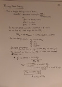 With the slightly rich head end, I will need to put 21.3% of the engine mass flow into the primary zone. Now, it should be understood that this is a rough estimate. When we have recirculation zones, some of the secondary air, the burning products, etc., can get pulled back into the primary zone and change this equivalence ratio. The slightly rich head end is a result of following the work of Bragg and others that have shown that the maximum consumption rate of incoming fuel-air occurs in a slightly rich mixture, not in a stoichiometric mixture. If you were trying to put a stoichiometric ratio in the head-end, you would target around 27.8% of the air flow to be in the primary zone. If you put 30%, you are at slightly lean condition, around a phi = 0.93 (phi is the symbol for the equivalence ratio). Definitely a safe spot...anywhere near a phi = 1 is ok and I will show some of the stability curves next time as well as discussing how other factors play into sizing the primary zone. We also will need to size the secondary and dilution zones, and then work out how we get the effective areas translated into geometric areas so that we can start drilling holes. Stay tuned! Chris |
|
|
|
Post by smithy1 on May 29, 2017 16:05:45 GMT -5
Right on Smithy, I'm starting a turbine build using a virtual copy of the GT6041. The turbo is being built by Competition Turbo with a 106mm comp inducer and 141mm exducer. It should be ready in the next 2-3 weeks. We have a common goal to optimize the same turbo to a combustion chamber. To the extent that is feasible lets coordinate and help each other by posting our design approach and test results. I expect to go through several combustion chamber iterations to converge on a compact and efficient design. It's all part of the fun. Data acquisition and analysis will be critical to the optimization process so I'll put a lot of emphasis on the data acquisition system and post the test results. I can't wait to get the build started. This Summer will be jam packed with combustion fun.  Tony Hi Tony, Thanks for your reply...and yep, I'm very interested in your ideas....As mentioned, my current combustion chamber is basically a result of using John's very good vaporizer setup, which worked very well too, right through it's P2 range, idle was smooth as silk even as low as 2psi P2 ....I've basically converted it to a single high pressure fuel injection version, I've just added or removed different bits 'n pieces to it to make it fit/work, it's not very professional TBH and low rpm/P2 performance is poor at best, I suspect there's a poor optimization/mismatch of air and fuel flows and I'd really like to get it performing at it's best. When running high rpm/P2 she seems to be "in the zone" and pressures, temps and indeed thrust appear good...so I can't complain there...John and Chris have seen it run in person and I'm sure they would agree the low end running isn't as good as it could/should be. Cheers, Smithy. |
|
|
|
Post by smithy1 on May 29, 2017 16:35:08 GMT -5
Hi Smithy, I am not sure I really understand what "fluffy" means when applied to combustion. Ha! My first guess is that you hear or feel some form of instability? It is common for combustors to become less efficient at lower flow rates due to the fuel/air ratios dropping relative to the full power conditions. If the combustor was just designed for full power conditions, it can experience instability or blow-outs at lower power conditions due to poorly staged air flows in the primary zone. In the design phase there are many operating conditions that are considered, but usually the high altitude relight and the full power take-off conditions are the big players. The work done by Longwell actually gives the best achievable boundaries for combustor stability due to it only being limited by the chemical reaction kinetics. In reality, our systems will never approach those values because our mixing will be much less effective, but it is a start. Longwell and later, Lefebvre, developed combustor loading parameters that allow us to estimate if we are in relatively stable regions of operation and we can explore those once we get some information. Do you have a sketch/photo of the liner with hole locations and sizes? We need any gap or hole, so we can accurately calculate the liner pressure drop. The C20B uses a liner pressure drop of around 3.5% dP/p...but for us to get the best chance of good combustor efficiencies, we would probably shoot for a 5% dP/p. Then we would need P3 and T3 (compressor discharge pressure and temperature) numbers if you have them at idle and full power. We can try to estimate mass flow from the compressor map and the combustor temp from the EGT if you have that. The one thing that does sort of stick out is that you are using a C20B injector in a much lower pressure machine. Those injectors produce some very large droplets at lower flow rates (> 200 micron SMD). This might be ok in the C20B because the higher discharge pressure also means higher discharge temperatures. The impact of the pressure suppressing the boiling point of the fuel is lower than the impact of increased temperature. Higher temperatures mean higher rates of evaporation and reaction from the droplets. If the droplets evaporate earlier, they are more likely to burn in the primary zone were they are supposed to. Now, you are not using the C20B liner, so you might have done something different to stabilize the flame. I would think that because of the lower temperature impacts, you would need to increase the recirculation strength in the primary zone, to draw in the larger fuel droplets. At ground idle the T63 has a T3 = 285F and a full power T3 = 590F. If you get up to a PR=4 with 2.66 lbm/s airflow, you a getting a peak T3 of around 387F. As you come down in power, the reduction in T3 could drop below the gnd idle T3 of the C20B and you might be experiencing trouble due to the reduced capability of the air to vaporize the fuel. The delay in droplet vaporization could cause combustion instability due to primary reaction location to being moved further downstream in the PZ and thus having less flame anchoring. Just a theory...hopefully we can work from the data how the combustor is operating. Good luck, Chris Hi Chris, Thanks for your reply. By "fluffy" I do indeed mean unstable combustion...and I'd suggest you're correct with the low comp discharge pressure, larger fuel droplets & lack of T3 temps issue. I have a pic of the original flame tube as built by John....all I've done is basically remove the upper "J" tube evap setup and fit a C20B upper to accommodate the single C20B fuel injector.  I don't have hole sizes/spacing to hand, John may have the relevant info..?? I suspect using a suitable flow rate fuel injector from say an oil furnace may help as well..?? I'm prepared to make a new flame tube to suit but I just need to be prodded in the right direction, I have a basic idea of what's needed but I would like to get it right before I start rolling, welding and drilling metal. I'm seeing maximum P2 pressures of ~40psi, I'm currently using an idle P2 of ~4-5psi....I'm afraid I have no idea of comp discharge temps as I don't currently have a temp gauge/sensor...but I suspect we could probably have a decent guess at it.. Cheers, Smithy. |
|
|
|
Post by smithy1 on May 29, 2017 16:53:48 GMT -5
Hi Smithy The flametube in my TV84 engine, 3.5" inducer 1.8 lbs/sec, worked OK , heres a couple of scanned photos ( pre digital camera days :-; )  It was 140 mm dia and ~1/3rd cu ft capacity , swirl vanes ( 12 of with 9 X 5 mm flow areas) surrounding simplex spray nozzle , 50 -750 psi fuel pressure , flametube domed cap had 36 X 3 mm holes Cheers John Hi John, I had completely forgotten about that engine of yours....I suspect that flame tube is pretty much what I should be shooting for....do you have info about the simplex spray nozzle and where to purchase?...obviously I'll need to get the correct flow rate and spray pattern etc... Did you use a solid or hollow type spray pattern?? Spray angle etc..?? Cheers, Smithy. |
|
CH3NO2
Senior Member
  
Joined: March 2017
Posts: 455 
|
Post by CH3NO2 on May 29, 2017 20:13:17 GMT -5
Hi Smitty, Why not make a new vaporizer system like John had? It should speed up the combustion process considerably. Injecting vaporized/cracked fuel against the top of the flame can will give it more time, distance and volume to mix/diffuse/burn. Whereas spraying a liquid directly into zone 1 will require a bit more residence time than the can was optimized for. (Just a thought)  Tony |
|
CH3NO2
Senior Member
  
Joined: March 2017
Posts: 455 
|
Post by CH3NO2 on May 29, 2017 20:19:24 GMT -5
Hi Chris, On the attached image below, I have a question on density of inlet flow. Density = P3/(R*T3) Is the value R = 53.35? When I first saw "R" I figured "universal gas constant" but I'm not sure what the value 53.35 is... Units of ft*lbf reads like a torque value but it feels like a mass flow lbm. Thanks, Tony postimg.org/image/8vxq9t4r9/ |
|
|
|
Post by finiteparts on May 29, 2017 21:01:53 GMT -5
Hi Tony,
That is the specific gas constant for air...you don't use the universal gas constant without the molecular weight to calculate the density of air at various conditions. When you add the molecular weight, you get the specific gas constant.
Smithy,
So if you just added a C20B upper, does that mean you included the swirlers that are in the dome of the C20B? If not, that would be a very likely something that would cause instability.
I agree with your comment. John's earlier combustor has a very nice air swirler that will create a very stable recirculation zone that will greatly aid in low end stability.
Good luck,
Chris
|
|
CH3NO2
Senior Member
  
Joined: March 2017
Posts: 455 
|
Post by CH3NO2 on May 29, 2017 21:27:59 GMT -5
|
|
|
|
Post by finiteparts on May 29, 2017 21:58:42 GMT -5
Hi Tony,
You can't divide by grams per mole when your mass in the gas constant is in lbm and slugs...you are mixing units. That is why they push that you check your units in engineering classes and thus why I stated it in the first post on this page.
universal gas constant / molecular weight of dry air:
1545.39 lbf*ft/(lbmol*R) / 28.97 lbm/lbmol = 53.35 lbf*ft/lbm*R
Good luck,
Chris
|
|
CH3NO2
Senior Member
  
Joined: March 2017
Posts: 455 
|
Post by CH3NO2 on May 31, 2017 11:32:54 GMT -5
Hi Chris,
Would you happen to have your turbo specs available? (Comp inducer, Turbine exducer and performance maps) I would like to run it through Jetspecs and see how it's output correlates to the math we are doing here.
That way when I do the same process with my GT6041 clone, I can run all the same calculations in parallel to see if I'm on the right track... and then to compare my calculations to John's/Smithy's GT6041 known working example.
If Lefebvre's math, jetspecs and the working examples are all in general agreement, it will give high confidence and predictability in the ability to make a good working design without excessive blind testing of flame can guesstimates.
We can put your turbo into jetspecs and post the results here as another reference point for understanding.
Thanks,
Tony
|
|
|
|
Post by finiteparts on May 31, 2017 21:06:21 GMT -5
Ok, so I thought I would do a quick comment on units, since it dawned on me that there may be some readers that didn't get it beaten into their process like engineering students. The process is REALLY helpful...and can often catch mistakes that would otherwise get missed. So let's do a simple equation... Newton's second law equation, specifically applied to a mass acted on by the acceleration of gravity on earth. 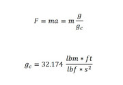 Everyone knows F=ma. In the metric system, things are simpler because force and mass are know by different terms. In the English system, force and mass can both be expressed in pounds...thus the proper way to write these units is to differentiate them by a suffix letter...lbm for pound mass and lbf for pounds force. We all know that 1 lbm = 1lbf here on our floating space rock, but if we solve F=ma straight out we would think that a 1 lbm acted on by earth's gravity would weigh 32.174 lbm*ft/s^2...what kind of unit is that? Turns out that is a slug (A slug is defined as the mass that is accelerated by 1 ft/s2 when a force of one pound (lbf) is exerted on it.)...wait...what is a slug you ask? It is an engineering students worst enemy! Slugs are hell bent on messing up the units on your test answers so that you look like an idiot...so you do the most logical thing possible. Convert everything to metric, work the whole problem and then convert back to english units at the end! Thus consuming all the time you need to answer other questions doing units conversion and introducing all kinds of new opportunities for errors. Ok...before you get on a rant about how superior the metric system is, know that I don't disagree, but the truth is, a good engineer should never be hampered by something as simple as units conversion...so suck it up and learn how to do it. The truth is that the world we live in is very globally connected and not everybody is on the same page. More importantly, history is not units specific. When you pick up a technical paper from 1947, even if everybody was currently using the metric system, you still have to figure units conversion out to figure out what they were presenting way back when and how to apply it to problems today. "A bad workman will never find a good tool." (French proverb, late 13th C. ) Who can save us from this evil? g_c (read that g sub c). Ok, let's use g_c in the equation and look at units conversion. At North Carolina State University, they require you to show your units in almost every class and they show you how to write them out and cancel them out just like you did back when you started fractions. Below you will see how I wrote the units out and then cancelled like terms. It may seem unnecessary, but when you have complicated equation and you want to make sure you got things correct, it is almost mandated to do this.  So we can see that 5 lbm = 5 lbf and order is restored to the universe! Really, there are many times in a rush I just tap out some numbers on the calculator and get answer that is wrong...off by 144 because I used in^2 when I needed ft^2...off by 3600 because it should have been in hours, not seconds...etc. I hope that helps! - Chris |
|
|
|
Post by finiteparts on May 31, 2017 21:34:20 GMT -5
Hey Tony, It will be interesting to see how these methods stack up. They are really targeted at different users, so we need to keep that in the back of our mind while we do any comparison. Here is my turbo plugged into JetSpecs combustor page... 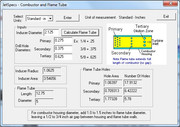 here is the compressor map...  The specs are: Compressor inducer: 2.125 in Compressor hub: 0.525 in Compressor educer: 2.65 (Extended tip = 2.75) Compressor b-height: 0.2 in Turbine Inducer:2.280 in Turbine exducer is 2.020 inches Turbine hub: 0.765 in Turbine b-height: 0.3 in I haven't been able to find a turbine map for the EFR6758 used in the Indy cars, which use a special thin cast single entry scroll that doesn't have a wastegate. -Chris |
|
CH3NO2
Senior Member
  
Joined: March 2017
Posts: 455 
|
Post by CH3NO2 on May 31, 2017 21:45:11 GMT -5
It does. Alot. This is awesome. I feel like I'm sitting at the front row of engineering class "Flame Can Design 101". Haha!  -------- For Indy car application your turbine is probably optimized for high efficiency in a narrow band at the top end. It may be safe to go with the high side of typical efficiency of a unit in that size range. Any idea of the A/R's? Possibly above 1.5? ---- PS - For dynamic pressure you might want to insert a "g" into the denominator. (Rho*V^2)/2g - The value 32.2ft/sec^2 is shown in the write up on the right but some people may miss it or become confused. ![https://postimg.org/image/8vxq9t4r9/]() --- PSS - If Lefebvre's math calculates something a bit different from jet specs that's OK. It's good to know and try both and see what happens in real world testing. I'll build and test both if they prescribe significant design differences. It would be a great learning experience to see how they differ in their performance. |
|
|
|
Post by finiteparts on Jun 1, 2017 21:04:18 GMT -5
Hi Tony, I am glad you are finding value in this post. You're almost there...The conversion factor there is g_c, not g. The problem with me putting a g_c in the equation is that people using the metric system don't need a g_c correction factor. The trick is to recognize when you need to put g_c or any other conversion factors in. So let's look at the reference dynamic pressure equation... 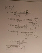 OK, so if I solve the equation as written, I end up with some odd units...lbm/ft*s^2. Now this is a valid set of units, just not recognizable to me as a pressure. Usually if the units contain a lbm, but you need a force unit, lbf, it should clue you in that you need to call in our good friend g_c. So if I divide by it, I now have a unit of pressure (force/area)...but I want lbf/in^2....so I divide by 12^2 = 144 and then I have the correct answer. You have to look at the units almost as a problem unto itself...solve the equation for the units that you need for the solution to make sense. I have no idea what the turbine housing AR is...it is not marked in any way. I will be instrumenting the housing if I build this turbine, so I can back out the flow area from the data if needed. Good luck! Chris |
|
CH3NO2
Senior Member
  
Joined: March 2017
Posts: 455 
|
Post by CH3NO2 on Jun 2, 2017 7:11:54 GMT -5
Hi Chris,
Jetspecs shows a total of 3.546 in^2 flow area .
Lefebvre math shows 1.8379 in^2.
If this is correct, it's a significant difference.
----
A separate but related question (For Chris and John)
What is the assumed discharge coefficient for the flame can holes prescribed by Lefebvre and Jetspecs?
----
Hi John,
Would you happen to know the % pressure drop Jetspecs uses across the flame can? It's 5% right?
Thanks,
Tony
|
|


