|
|
Post by finiteparts on Feb 19, 2017 15:36:34 GMT -5
Patty, In response to this, jetandturbineowners.proboards.com/post/18179I thought that I would just start a new thread to discuss all things "combustor design" related, starting with this one on swirl stabilization. So to start from the absolute fundamentals, let's talk about some combustion basics. We know that to have a combustion reaction occur, we need a fuel and oxidizer and a source of ignition. So if we go to something simple that we all know, a candle, we can gain some basic understanding and compare it to our combustor design. When we light a candle, we set-up a very similar system to a combustor. If we think of the wax as a very viscous liquid hydrocarbon, we can draw a parallel to our kerosene liquid fuel. The wax itself will not burn in it's liquid state, it has to be converted to a gas to burn. So when we apply a flame to the wick to start the process, we are melting the upper most layer of wax on the candle and any wax that is still in the wick. As the wax is further heated, it phase changes to a gas and then mixes with the updraft of air to produce the combustible mixture that feeds the flame. Once initiated, the radiational heating of the flame continues the process of melting the wax into a low viscosity liquid that flows by capillary action up the wick into the hotter region where it flashes to a gas state and then flows into the flame...and the cycle continuously repeats. 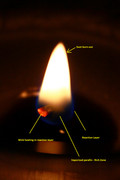 Now to compare this to our combustor designs. The wax is the kerosene fuel flowing in, which must be heated to a point that it flashes to a gas so that it can participate in the combustion. The rate of vaporization is a function of the ambient temperature that the fuel is spraying into. This is where the two major fuel processing methods diverge. The first major fuel processing method is spray atomization. The goal of atomization is to break up a stream of fuel into as many smaller droplets as possible to increase the surface area from which the fuel can evaporate. Since evaporation occurs between a liquid to gas interface, increasing the area of that interface increases the evaporation rate. As can be seen in the curve below, if you break up a given volume into a number of droplets, you increase the surface area 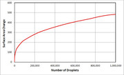 As an example, if we started with an 0.080 inch diameter jet and "took" a .125 inch long section of it, to get to a spray of 30 micron diameter droplets (which is roughly considered a fog and thus would be suspended in air over time), we would have over 750,000 droplets and we would have increased the available surface area from which to evaporate from by about 350 times. If we could get the droplet sizes down to 12.5 microns, we could increase the surface area over 1000 times it original value! But, evaporation is not only a function of surface area, it is more complex. Diffusion and evaporation both compete to transport the mass across the gas-liquid boundary. If we take these as the rate limiting processes, then two equation illustrate the variables involved. You can read more about this in J.J. Bikerman's "Surface Chemistry, Theory and Application". 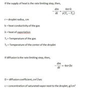 If we look at these equations, we can see that there are other things that can help us get the fuel into a gaseous state...a larger temperature gradient, diffusion coefficient, lower latent heat of vaporization, etc...but the easiest thing to control is the droplet diameter. By inspection, we can see that if we took the same volume of fuel and broke it up into a thousand smaller droplets, we would get a 100 fold increase in evaporation or diffusion depending on which one was dominant. (remember that volume is a cubic function, so if we break it into a 1000 droplets, the droplet diameters would be = r/10) Another equation is provided to calculate the rate of change of the droplet mass (dm/dt) assuming that it is moving through the ambient air is shown below, 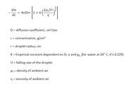 Since this equation assumes that the droplet is large enough to fall through the air, it is considered larger than a fog. This one is tougher to use, but it may be a better fit if the coefficients can be found for a kerosene type fuel at our operating point conditions. We now know that we want to have a larger number of smaller droplets, but how do we do this? The issue we have to face with atomizing liquid is that it takes work to create the surface tension need to hold the smaller droplets together. So, in order to make smaller and smaller droplets, we HAVE to do work on it. We can do work on it by the same way we do work on other fluids, with pressure, temperature or velocity (potential or kinetic work). We will come back to this for each method we discuss, but this a key thing to keep in the back of your mind, that it takes work to increase the liquids surface area. The second major method of processing the fuel into the vapor state is probably very familiar to most on this site, that being heating. Vaporizers are simple way to push the internal energy of the liquid over the hurdle of phase change, but durability and sizing are challenges. I will differ this discussion for a few posts, but I promise to come back to it...there is some very nice information out there on this. We now have a large number of drops that are evaporating just upstream of the flame, just like the candle. The fuel vapor and air are mixed and ready to burn, but they need something else to burn, they need the ignition energy to get them over the chemical potential energy hump before they can self propagate. Let's assume that we are already lit off and running in a steady state manner. The way the reactants usually get lit off in the candle is that the reaction rate is just in balance with the reactant flow speed and as such you get a stable flame front. But, the turbulent flame speed for kerosene-air flames is under 16 ft/s, so if the mean flow speed is larger than that, the reaction front and thus the flame cannot propagate, it just gets blown off. If you think about a candle, you know that as you blow more and more on it, the flame gets more noisy, unstable and eventually, it just can't "hold" on and blows off when the reaction rate is slower than the reactant flow speed. This is the reason that we need to design the combustor to have flame anchoring regions or devices...which I will put in the next post. ~ Chris |
|
|
|
Post by finiteparts on Feb 19, 2017 19:29:55 GMT -5
From the previous fundamentals discussion, we know that we need to come up with some way to stabilize or anchor the flame since it is likely that are combustors will be too small to have a mean internal flow speed below the turbulent flame speed. If we start at the very basic idea of putting a bluff body in a moving flow, we can get an understanding of what we might need to anchor a flame in a flow which has it's mean flow speed above the turbulent flame speed. Lets just look at a cylinder in cross-flow. 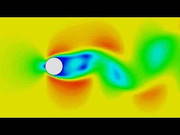 If we look just on the downstream side we see that there is region of low flow velocity caused by the body modifying the flow streamlines in such a way that they cannot close back fast enough. This low velocity region can be tailored such that the mean flow speed in the wake region is below the turbulent flame speed and thus can be used to anchor the flame. There will be a need to exchange the reacting products with a fresh fuel/air charge, so there can't be a fully "dead" cavity, it has to be partially open to the flow. This is just like cupping your hand around a candle to protect it from the wind. On this cylinder example, if we were to use it as a flameholder and like many afterburner arrangements, let's say we inject the fuel upstream such that there is sufficient time to convert the liquid fuel into an air-vapor mix. As the air-fuel mix passes around the body, some of the air-fuel mix will get pulled into the wake region where it will get ignited by the burning air-fuel mix that came in before it and so on in a self propagating cycle. The recirculation zone it the key to a stable anchoring of the flame because it introduced the already burning fuel-air mix with the fresh, unburned fuel-air mix as it comes in such that there is a continuously burning flame. The low turbulent flame speeds demand a low velocity region in order to anchor the flame and create a stable combustor, so how can we do this other than with bluff body flameholders? The primary method we see in the vast majority of combustors is swirl stabilization to create a zone of recirculation just downstream of the injector. Swirl-stabilization hinges on the fact that strongly swirling flows form very low static pressure regions in the center of the swirling flow. This low static pressure region can cause the flow stream to get pulled in and reverse such that they form a recirculation region in the center, often called a tulip or a bubble (due to its shape). Think about a tornado...the center flow pulls stuff up into the low static pressure "eye" in an opposite sense to the surround downdraft flows away from the center. So, to design a swirler, we need to target a certain amount of swirl momentum in order to achieve this recirculation. We can do this by calculating what is known as a swirl number. The swirl number give a sense of the amount of rotational energy that is imparted to an axial flow. Lefebvre gives a rule of thumb for a minimum flow number of 0.6, which below this value, the inner static pressure is insufficient to produce a recirculating flow. A representative swirler was selected (hub diameter = 0.75 inch, Swirler Diameter = 1.15 inch) and a curve was generated to show the behavior of the swirl number for a flat vane style. 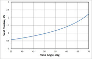 This was calculated from an equation proposed by Beer and Chigier for flat vane swirlers as, 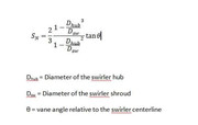 The amount of swirl plays into the amount of mass flow that gets entrained in the recirculation, and in general, the larger the swirl, the larger the amount of mass flow entrained in the recirculation bubble. But as is that case for every engineering problem, there is a trade. As the amount of swirl is increased, the pressure loss through the swirler also increases. So for a fixed amount of pressure loss for a combustion system, there may be a limit on how much you can push the swirler. One of Arthur Lefebvre's grad students did a thesis on the aerodynamic features and how they effect the recirculation bubble. It can be found here: dspace.lib.cranfield.ac.uk/handle/1826/4612Lefebvre's first edition "Gas Turbine Combustion" book gives a very concise design section on swirler design and it's impact on the recirculation bubble. I highly recommend finding an earlier edition of this book...the second and third editions are ok, but for some reason, they ommitted some really valuable information. I will try to work through an example to help illustrate this lengthy discussion. ~ Chris |
|
|
|
Post by finiteparts on Feb 19, 2017 22:23:42 GMT -5
Ok...for the example combustor, I will be using the EFR6758 map and sizing to a design point of 45 lbm/min at a PR = 3.2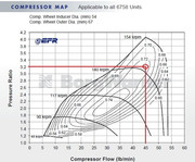 So if you run through the numbers, this gives a fuel mass flow of 0.0140 lbm/s (50 pph). With the weight of kerosene being around 6.6 lbm/gal, that puts it at a fuel nozzle flow of 7.6 gph. If you were to size a single pressure atomizing nozzle to flow this, you would first need to find the idle or light-off fuel flow rates, which size the lowest fuel pressure point. I haven't worked those out yet, so I will come back to this. The combustor is sized mainly using the methods in Lefebvre's "Gas Turbine Combustion" book, with a little help from a few other sources. The first thing you do in this process is to calculate some reference conditions...area, velocity, dynamic pressure, etc. With a selected pressure drop target, which was 5% for this design (and a very common value it combustion), you can calculate the effective area of all the holes in the liner. The reason that you need to have a noticeable pressure loss across the liner is because you need a certain amount of mixing to make sure that you can achieve efficient combustion. It would be great if you could run a 0.5% pressure loss across the combustion liner, since every bit of pressure loss is a loss on the total thermodynamic cycle. But!!! A 0.5% pressure loss is not enough to drive the primary and dilution jets into the combustor core flow. With the low pressure ratio, the jets would just waft in and lay over as the combustion gases passed by...they would not penetrate deep into the combustion gas flow and really mix like they do with the higher pressure drops. 5% is a good compromise as it is not a massive hit to the cycle efficiency, but it provides enough energy to really push the flow in there and mix things up. Ok...so we selected a pressure drop and from that we calculated the effective area that we need to produce that pressure drop across the liner. This can be thought of like the flow through an orifice...you need a certain orifice diameter to achieve a certain pressure ratio across that orifice for a given flow rate. My design values are thus far: Liner outside diameter = 5.0 inch
Combustor casing inside diameter = 6.0 inch
Compressor discharge temperature, T3 = 340 F
Compressor discharge pressure, P3 = 47 psia
Pressure drop = 5%
Liner flow through effective area = 1.838 in^2
Casing to liner annular passage flow speed = 24.1 ft/sThe next step is to figure out the air splits to each zone. Usually designing for a near stoichiometric fuel-air ratio (FAR) in the primary zone is a safe way to go, but sometimes, especially when there are altitude changes, you need to design a bit higher so that at your leanest condition you don't wander below the lean blowout condition, which is just like it sounds...a point were the FAR is so lean that stable combustion becomes impossible and the flame blows out. Remember, the stoichiometric FAR is the ideal FAR were you have just enough air to burn the given amount of fuel. Ideally, this would be the point were you would have your highest flame temperatures, but in reality, your highest flame temperatures occur when you are slightly rich, because at high temperatures, some of your thermal energy is taken to split molecules like N2 into two N atoms. This is called dissociation. Sometimes you might want to design the FAR below the stoichiometric ratio to keep the flame temperatures cooler so you can increase the durability of your combustor. For this combustor, I selected a primary zone FAR of 0.088. This gives me an equivalence ratio of 1.29, where the equivalence ratio is the FAR / stoichiometric FAR...thus an equivalence ratio of 1 is at stoichiometric, below 1 is a lean condition and above 1 is a rich condition. So I am targeting a slightly rich headend to keep the dome temperature down slightly. Once I have a target equivalence ratio for the primary zone, I use a chemical reactor software, "KINETX", that came with Jack Mattingly's book, Aircraft Engine Design. Using this, I can play with the sizing to see how it impacts combustor efficiency. KINETX solves the Kollrack two-step pyrolysis mechanism for jet fuel kinetics (C12H23), which is a 30-step reaction mechanism where the first two steps are global in scope. The first screen shot shows the input screen. You are setting up the reactor network and defining the flows...  The results screen shot shows the results at each reactor module. 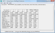 The reactor network is a modified Bragg reactor. A pioneer in gas turbine development in Britain, S.L. Bragg devised a reactor model to approximate the behavior of the combustion chambers used in gas turbines, by combining a WSR primary zone and a PFR secondary zone. The primary zone is modeled as a well stirred reactor (WSR). The WSR assumes that every fluid particle entering the system has access to every other particle in the reactor. This assumption is based on the idea that the turbulent mixing and diffusion is large due to high recirculation within the reactor. Defining the scale of the mixing within the reactor can further refine the WSR. The first mixing mode is macro-mixing which assumes that the mixing is complete on a scale compared to the volume of a small size, but on a molecular scale, it is still quite large. Then micro mixing is the second mixing mode, which assumes the mixing is complete on a molecular scale, often called volume burning. The primary zone discharges into the secondary zone that is modeled as a plug flow reactor (PFR). The PFR assumes that there is no axial mixing, i.e. no forward or back mixing. This then allows for the reaction to progress radially as the flow passes through the reactor. The tertiary zone is also modeled as a PFR. The network is shown schematically as:  Now that the sizing and flow splits are defined, the number and size of the jets can be selected. I will have to continue this later, since it is getting late. I hope this has been insightful so far to those unfamiliar with combustor design. Chris |
|
|
|
Post by madpatty on Feb 28, 2017 5:40:20 GMT -5
Hi Chris,
Very insightful information. I tried using CHEMKIN but never got this far.
Waiting badly for the next class on this subject.
Cheers.
|
|
|
|
Post by madpatty on Feb 28, 2017 5:48:13 GMT -5
Hi Chris,
One thing that i have never came to know is how the swirler works.
How it creates a low static pressure at it centre?
And low static pressure means hogher dynamic pressure component(assuming total pressure is constant in that region at that time)
So higher dynamic pressure component means high velocity so how can a flame stabilise in high flow velocity.
Please correct me of i am wrong anywhere.
Thanks.
Patty
|
|
|
|
Post by finiteparts on Mar 3, 2017 21:41:41 GMT -5
Hi Patty, That is correct thinking. You do get some very high velocities in the recirculation region...but the velocities are switching direction in the recirculation zone, so there has to be a stagnation point were the velocity is zero and in this way, the rotational flow due to the recirculation sets up a toroidal region (donut shaped) of very low velocity. It is in this toroidal region that the flame finds a nice low velocity anchoring spot. I have a CFD model of a radial swirler that illustrates this quite well. Also notice how the primary jets are used to energize the primary zone vortex, this the need for proper placement of these jets. 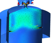 I just made a quick axial swirler combustor model and I am running it right now. Hopefully I will have results in a few hours to show the same recirculation zone that it creates.  Chris |
|
|
|
Post by finiteparts on Mar 4, 2017 16:16:44 GMT -5
Here is the quick CFD run of the cold flow (non-reacting) flow through the can style combustor. This combustor was modeled with 45 degree flat swirler vanes and the boundary conditions were set to give a 5% pressure drop between the diffuser inlet and the combustor outlet. We can think of RANS CFD as the modern day water table that was used decades ago to estimate the flowfield that might exist in the combustor...at least better than guessing! The recirculation can be easily seen and hopefully this helps illustrate how we can use swirlers to create a stable flame anchoring in the primary zone. 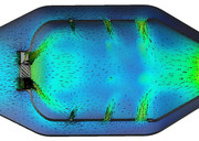 If we zoom up, we can get a better look at how the primary jets help to set up the recirculation zone. Also, you can see from the velocity vectors that there is a point in the center of the toroidal vortex that has near zero velocity and thus works as an excellent flame anchoring location.  If you look closely, you will see that there is reversed flow coming from as far back as the secondary zone. The reverse flow carries the reacting products forward into the primary one were they help to ignite the new fuel/air that is coming in and that is why recirculation is a basic method to create a stable combustion region. If I turn off the vectors, you get a visual sort of idea on how the jets penetrate into the core flow.  You can see that for the same static pressure drop across the liner, the larger the jet, the farther it will penetrate into the core flow. This is due to larger momentum the jet gains as it goes up in diameter. With larger amount of momentum, the jet can overcome the axial flow momentum and get in farther. ~ Chris |
|
|
|
Post by madpatty on Mar 10, 2017 11:29:45 GMT -5
Hi Chris( finiteparts), There was another question that was coming to mind which is as follows:- What is the average value of turbine inlet velocity(first stage NGv outlet velocity) in various gas turbine engines? Do they all run choked NGVs and/or on what does it depends? Thanks. |
|
|
|
Post by finiteparts on Mar 12, 2017 16:57:45 GMT -5
Hi Patty, Many engines out there, even with modest compressor pressure ratios, operate with the first stage NGV choked. If you design for the max work condition, you are trying to impart as much tangential velocity to the NGV exit flow as possible. The practical discharge speed is when the NGV just choke or maybe just a touch over. Supersonic blading on NGV has been done, but shock wave interactions with the blades cause large irreversible losses and most engines keep the NGV exit discharge flows near a Mach number of 1. The nozzle efficiencies of most NGV are high enough that there is not a large shift in required nozzle critical pressure ratio as compared to the isentropic critical pressure ratio. If we assume that the exhaust is essentially just heated air (ignore the products of combustion and their impact on gas properties), then the ratio of specific heats (k) can be approximated as around 1.33. Plugging that into, (P2/Pt1)crit = (2/(k+1))^(k/k-1) *- Edited on 4/14/2019 to correct typo as suggested here:
jetandturbineowners.proboards.com/post/26144gives a critical pressure ratio of around 0.540. Since we are usually more concerned about the inverse of this, namely the total pressure at the NGV inlet to the static pressure available at the throat, we flip it and get a total to static critical pressure ratio of 1.85. Usually, the minimal cross-sectional area in the turbine stage is the NGVs, so once your stage pressure ratios start getting over 3:1 area, they can enter a region were the flow properties are such that choking can occur. If you look at turbocharger turbine maps, you can see that the minimum cross-sectional area of the scroll housing (called the tongue) sets the choke flow and is often just over the 1.89 pressure ratio (since they flow them at standard day conditions where the ratio of specific heat is around 1.4). In reference to this critical ratio discussion, I noticed that Ron ( turboron ), you mentioned... "You will find the calculation in textbooks like Zucrow for example. It is 2.4 for air." in this post, jetandturbineowners.proboards.com/post/18899I am not sure how you arrived at that number, but you might want to check on that number. Of course there are other variables that also play into this...turbine stage reaction is a prime one, since it defines how the pressure ratio is split across the stage. I hope that helped. Chris |
|
|
|
Post by madpatty on Mar 13, 2017 17:44:04 GMT -5
Hi Patty, Many engines out there, even with modest compressor pressure ratios, operate with the first stage NGV choked. If you design for the max work condition, you are trying to impart as much tangential velocity to the NGV exit flow as possible. The practical discharge speed is when the NGV just choke or maybe just a touch over. Supersonic blading on NGV has been done, but shock wave interactions with the blades cause large irreversible losses and most engines keep the NGV exit discharge flows near a Mach number of 1. The nozzle efficiencies of most NGV are high enough that there is not a large shift in required nozzle critical pressure ratio as compared to the isentropic critical pressure ratio. If we assume that the exhaust is essentially just heated air (ignore the products of combustion and their impact on gas properties), then the ratio of specific heats (k) can be approximated as around 1.33. Plugging that into, (P2/Pt1)crit = (2/(k-1))^(k/k-1) gives a critical pressure ratio of around 0.540. Since we are usually more concerned about the inverse of this, namely the total pressure at the NGV inlet to the static pressure available at the throat, we flip it and get a total to static critical pressure ratio of 1.85. Usually, the minimal cross-sectional area in the turbine stage is the NGVs, so once your stage pressure ratios start getting over 2:1 area, they can enter a region were the flow properties are such that choking can occur. If you look at turbocharger turbine maps, you can see that the minimum cross-sectional area of the scroll housing (called the tongue) sets the choke flow and is often just over the 1.89 pressure ratio (since they flow them at standard day conditions where the ratio of specific heat is around 1.4). In reference to this critical ratio discussion, I noticed that Ron ( turboron ), you mentioned... "You will find the calculation in textbooks like Zucrow for example. It is 2.4 for air." in this post, jetandturbineowners.proboards.com/post/18899I am not sure how you arrived at that number, but you might want to check on that number. Of course there are other variables that also play into this...turbine stage reaction is a prime one, since it defines how the pressure ratio is split across the stage. I hope that helped. Chris Hi Chris, You got that post exactly at the same point where it confused me too. I was also thinking how that number came out to be 2.4 Cheers. |
|
|
|
Post by finiteparts on Apr 2, 2017 16:07:48 GMT -5
To help illustrate how the combustor flow field is modified by the presence of a mixing, diffusing gas and reaction, I ran a simplified reacting CFD version of the previous model. As with any computational model, there is an error relative to the actual physical process. The trick is to determine how correct the model is and can the information guide the design to achieve a better product. Since the purpose here is only illustrative in nature, we will not get too bogged down in the absolute values, we will just look at the trends. As with any computation, it is critical to explain the simplifying assumptions that have been used to solve it and that is especially critical with CFD. The first assumption used for this run is that I ran the combustion reaction with a Eddie Dissipation Model (EDM) using gaseous methane as the fuel. The EDM approach assumes that the chemical reaction rate is much faster than the turbulent mixing rate. This means that the model drives the progress of the combustion reaction by the amount of time it takes to mix at the molecular level. This assumption is ok for a first pass on a non-premixed system, but because it does not include reaction rates that are tied to the chemistry, it will deviate from the actual reaction sizing. The mechanism for the reaction of the methane fuel is a multi-step model, but to keep it simple, I only evaluated O2, CO2, H2O, NO and N2 species. This helps because my computer is not loaded up with RAM and these models get big, FAST!!! YOu will also notice in the results that the interior mesh is larger than I would like, but when I tried to refine the mesh, I ran into memory allocation errors. In the first image, we can see that the primary reaction surface appears to match the tulip shape that we would expect. If you plot the species mass fractions, you can see that there is some reaction happening in the fresh oxygen that is coming in from the secondary jets, while the reaction is completed (or frozen) in the vicinity of the tertiary jets. The depth of the jet penetrations can be seen quite well and it should be obvious that to get deeper jet penetration, you want a larger dilution hole.  If we zoom into the primary zone and plot velocity vectors on the plane, we can really see how the recirculation is helping the primary zone. As the primary reaction occurs, some of it's reacting products are carried back forward to where the fresh air and fuel is coming into the chamber. The reacting products supply the needed energy to initiate the new reactions in a continuous cycle. It is interesting to compare the reacting flow field to the un-reacting flow field that was shown previously. 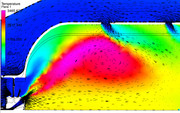 Finally, the beauty of running reacting CFD is that you can pass the reaction information to other systems. In this simulation I also estimated the radiant heat load and the effect of convective heating/cooling on the liner wall adjacent surfaces. Remember, this is not the metal wall temperatures, this is the gas temps just at the wall. We would need to port these results into a mechanical thermal model to see how the metal behaves when subjected to this gas temperature map. This shows the results...  The hot streak is due to the limited number of fuel injection holes. The swirl carries the highest concentration of reacting products to this location and it is effects like this that can cause liner buckling due to the severe thermal gradients imposed through the liner metal thickness. Since nickel alloys melt in the 2100-2300F range, the hot spot would be concerning. The thermal model would help us see how well the cold air on the outer surface of the liner works to conduct the high heat load on the inner liner surface away. If I have time I will try to run that to show as an example. - Chris |
|
|
|
Post by finiteparts on May 11, 2017 0:22:36 GMT -5
It's been a while since I posted last, but sometimes painting a baby's room or making mom happy is more important than turbines...really...ha! The primary driver for a well designed combustor is a well designed primary zone. The primary zone gets everything going and anchors the reaction to make the combustor stable over a wide operating range. For our purposes, the work done way back when, may still be applicable. For the low emissions, high heat release combustor of modern day, the use of more advanced means to make sure the reactions occur in narrow temperature zone and short time scales that really don't make sense for our low pressure ratio machines. If we start with a bit of history, it may help to clarify the purpose of some of the common design targets. Back in the 1950's, there was some work done at Shell Oil company that really changed the way combustors were designed. Two researchers, John Longwell and Malcolm Weiss developed a method to test the effects of only the chemical kinetics on the amount of heat release that you could get out of a reactor vessel, or what is commonly called "combustor loading" in the industry.  John Longwell (above) developed a "jet stirred reactor" that had some very high internal mixing rates due to the sphere in sphere arrangement. IN fact the "stirring" was so vigorous and complete that it is often referred to as a perfectly stirred reactor (PSR).  The fuel and air mixture was injected in from the inner sphere and mixed with the already burning or completely burning mixture in the outer sphere. Finally, the burnt mixture would exit the vessel via the larger outer holes. John Longwell went on to teach and research at MIT and lead many important combustion related research projects for decades. Their work showed that there was a maximum heat release that could be liberated in a confined volume. There work suggested that the maximum space heat release rate was around 300 million BTU/(ft^3*hr*atm^1.8) and this maximum heat release rate occurred near the stoichiometric FAR. There are some nice plots of this out there that I will look for and post later. Their work showed that for a given heat release rate there exists chemical kinetics drive boundaries that define where a flame can and cannot exist. These boundaries define the rich and lean blowout limits for any given combustor loading. Their work proliferated across the combustion community and spawned hundreds of research projects on the combustion of various fuels, reaction rate theory and combustion operability limits. One of the researchers that latched onto this new tool was S.L. Bragg, a chief scientist at Roll Royce. Using this new tool he worked out that to get the maximum heat release for a given volume, you need to have the chemical reactions happen as fast as possible. He found that this corresponded to a primary zone optimal burning ratio of 80% of the stoichiometric flame temperature, on the rich side of stoichiometric. This was not intuitive! Intuition would suggest that you would want a stoichiometric primary zone, but it turns out that as the reaction progresses, it gets harder to finish due to the local FAR shifting to a rich or lean condition, which drives the reaction rate lower. Rich conditions reduce reaction rates due to the available heat capacity of the fuel, while the lean condition the lack of local fuel drive the reaction rate down. This led to the Bragg combustor, which has a WSR which simulates the primary zone mixing, followed by a plug flow reactor that simulates the dilution zone burnout of the remaining unburned fuel from the PZ flow. This theory takes a bit of work to understand, so I will come back to it in another post. Ok...so far we have learned that in order to get the highest heat release per volume combustor, the primary zone needs vigorous mixing with a FAR that achieves an 80% of the stoichiometric temperature rise. The FAR must be above the lean blow out (LBO) boundary and below the rich blow out (RBO) boundary to achieve stable combustion. But there is another big factor that drives the operability of the PZ and this is the temperature. Chemical reaction rates are functions of temperature (and pressure). In order for molecules to react, they must be able to gain or loose energy and one of the primary paths is collisions. As molecules heat up, they move around faster and thus they can collide more and with more energy. The more energy is important because many multi-body reactions in gas kinetic theory require a certain amount of "activation" energy to break the existing chemical bonds or to form new ones. Pressure also accelerates reactions...doubling the pressure quadruples the number of collisions, thus increases the reaction rates. When we are talking about combustion reactions, one of the process steps involves gaining enough energy to break the bonds, which takes some amount of time to transfer form the environment to the reactants. This amount of time is known as the ignition delay time. Ignition delay time is very important, especially to the IC engines...without ignition delays, the engine would just knock all the time, but we can get fuels with higher octane ratings that have longer ignition delay times to suppress the engines propensity to knock. But for gas turbines, ignition delay time means that to burn the fuel as fast as possible, we need to heat it up as fast as possible in/or before the primary zone. How do we do that? Recirculation of the reacting flow. Room temperature ignition delay times can be measured in seconds and this is one of the reasons that you get the larger flames out the exit on cold starting engines. When the residence time of the air going through the combustor is measure in milli-seconds, a 1 second ignition delay time means that combustion isn't going to happen in the combustor. If we can get the reactant temperature up to 800 or more, then the ignition delay times start to get really small and the combustor is no longer "reaction rate limited". I will try to find some data on kerosene ignition delay times and post them in the future. The temperature also helps with liquid fuel evaporation, which can also be a reaction limiting process. But I will save that for next time. - Chris |
|
|
|
Post by madpatty on May 11, 2017 20:47:12 GMT -5
Hi Chris,
I have read all this in my Advanced Combustion course at University but I understood it completely today.
Thanks for keeping on sharing the valuable information.
Cheers,
Patty
|
|
CH3NO2
Senior Member
  
Joined: March 2017
Posts: 455 
|
Post by CH3NO2 on May 12, 2017 8:58:49 GMT -5
... 1) He found that this corresponded to a primary zone optimal burning ratio of 80% of the stoichiometric flame temperature. .... the primary zone needs vigorous mixing with a FAR that achieves an 80% combustion efficiency. The FAR must be above the lean blow out (LBO) boundary and below the rich blow out (RBO) boundary to achieve stable combustion. --- 2) When we are talking about combustion reactions, one of the process steps involves gaining enough energy to break the bonds, which takes some amount of time to transfer form the environment to the reactants. This amount of time is known as the ignition delay time. Ignition delay time is very important, especially to the IC engines...without ignition delays, the engine would just knock all the time, but we can get fuels with higher octane ratings that have longer ignition delay times to suppress the engines propensity to knock. But for gas turbines, ignition delay time means that to burn the fuel as fast as possible, we need to heat it up as fast as possible in/or before the primary zone. How do we do that? Recirculation of the reacting flow. Room temperature ignition delay times can be measured in seconds and this is one of the reasons that you get the larger flames out the exit on cold starting engines. When the residence time of the air going through the combustor is measure in milli-seconds, a 1 second ignition delay time means that combustion isn't going to happen in the combustor. If we can get the reactant temperature up to 800 or more, then the ignition delay times start to get really small and the combustor is no longer "reaction rate limited". I will try to find some data on kerosene ignition delay times and post them in the future. The temperature also helps with liquid fuel evaporation, which can also be a reaction limiting process. But I will save that for next time. - Chris Hi Chris, Thank you for this very informative thread. Questions: 1) 80% of stoichiometric. To be sure I am reading this correctly, optimum combustion efficiency occurs with a 20% excess of air in the PZ? 2) Ignition delay times. Jet fuels like kerosene and diesel are typically used for their availability, cost, safety but what if we were to modify the fuel chemistry? Diesel fuel has great density but very low vapor pressure. If the fuel were spiked with 10% diethyl ether it would completely change the fuel flash point, autoignition temperature, flammability limits and ignition delay. If a mixture such as this were sprayed into a hot vaporizer tube the diethyl ether would vaporize out of solution well before the diesel has a chance to vaporize. Although the FAR within the vaporizer tube is much too low for combustion of the diesel, it wouldn't be too low for the ether. The ether would begin burning the moment it comes in contact with the hot vaporizer tube. I imagine there would be a reaction zone within the vaporizer tube itself. A reaction that would almost just as quickly extinguish itself as the oxygen is consumed and the diesel is vaporized.... but now the difference is there will be increased tube outlet temperatures, more complete vaporization/cracking of the diesel and radical reaction products ready to burn once it flows into the combustion chamber. You mentioned in John's Fat Boy 12/118 thread "Remember, on vaporizer combustors, you want to keep the vaporizer discharge flows very rich to inhibit ignition in the tubes." If the vaporizer tube were not damaged or burned by doing this, is there another reason to NOT start combustion in the fuel rich vaporizer tube? Conversely, if the vapor tube was designed with the intent of initiating fuel rich combustion within it, would there be a down side to this? Thanks, Tony |
|
|
|
Post by finiteparts on May 13, 2017 1:28:51 GMT -5
Hi Tony, "1) 80% of stoichiometric. To be sure I am reading this correctly, optimum combustion efficiency occurs with a 20% excess of air in the PZ?"
Sorry...I corrected the description in the post above to show that you actually want to be on the rich side of the stoichiometric peak. And it is where the flame temperature is 80% of the peak stoichiometric flame temperature...so if you run the calcs, you will be at an equivalence ratio of 1.7 to 1.8. If you assume a 20% deficient fuel condition (by mass), that only gets you to a ER ~ 1.25.
"2) Ignition delay times. Jet fuels like kerosene and diesel are typically used for their availability, cost, safety but what if we were to modify the fuel chemistry? Diesel fuel has great density but very low vapor pressure. If the fuel were spiked with 10% diethyl ether it would completely change the fuel flash point, autoignition temperature, flammability limits and ignition delay. If a mixture such as this were sprayed into a hot vaporizer tube the diethyl ether would vaporize out of solution well before the diesel has a chance to vaporize. Although the FAR within the vaporizer tube is much too low for combustion of the diesel, it wouldn't be too low for the ether. The ether would begin burning the moment it comes in contact with the hot vaporizer tube."
You don't want burning in the tubes. You want to get the vaporization process started and then use the discharge velocity out of the tubes to create a airblast atomization of the fuel. If you have large droplets, the impact on the dome is a really good method to break them up and flash them to vapor. If you run the heat transfer numbers, you would need very long tubes to vaporize all the fuel coming in. SNECMA and Rolls ROyce realizedthis and because of the airblast atomization at the vaporizer outlet being so effective, they actually reduce the length their vaporizers with no impact to performance. You actually want to keep some of the fuel in a liquid state all the way to the end of the vaporizer tube to cool the tube wall. In a high temperature, oxidizing environment, you need to keep the metal temperatures down so as to keep the rate of metal oxidation low. If you get the metal temperature too high, it will actually oxidize rapidly...which is called "burning"...ha!
"I imagine there would be a reaction zone within the vaporizer tube itself. A reaction that would almost just as quickly extinguish itself as the oxygen is consumed and the diesel is vaporized.... but now the difference is there will be increased tube outlet temperatures, more complete vaporization/cracking of the diesel and radical reaction products ready to burn once it flows into the combustion chamber. You mentioned in John's Fat Boy 12/118 thread "Remember, on vaporizer combustors, you want to keep the vaporizer discharge flows very rich to inhibit ignition in the tubes.""
If the vaporizer tube were not damaged or burned by doing this, is there another reason to NOT start combustion in the fuel rich vaporizer tube?
Conversely, if the vapor tube was designed with the intent of initiating fuel rich combustion within it, would there be a down side to this?
My guess is that if you are putting hot gases on both sides of the vaporizer tube walls, controlling the tube temperatures will be tough. Rapid oxidation of the tubes is going to be a problem...it might give you a chance to learn the first rule of combustion design, "If it burns off, leave it off."
Another concern would be a sudden shift in the flow splits across the liner. The heat release in tube will create blockage and the effective area of the tube will drop. More air will go through the other liner holes and modify the FARs in all the different zones created in the combustor.
But this is all conjecture till you test it out. I mean Jet-B has naptha in it and JP-4 is 50/50 kerosene-gasoline blend...so you might be ok to run low percentages of diethyl ether. I really wouldn't want burning in the vaporizer tubes, but in a space limited application, it might help...
Good luck,
Chris |
|


