|
|
Post by racket on Sept 9, 2015 6:26:11 GMT -5
Hi Anders
Looking at your last video , at the 22-23 second mark , just as you were passing by the videoing guy , if you stop the video and checkout your interstage ducting colouration, there ain't none , if you were running 1050 C it would be glowing a bright yellow .
There could be some sort of "aberration" with the temp reading when the thermocouple is exposed to the high speed gases and none when a static test is being conducted out of the machine , the reason I suggest this is because I once tried measuring T2 on my TV84 engine , and I got nothing but very strange readings bearing no resemblance to what they should have been, they were too far away from reality , I checked the thermocouple in boiling water and it gave the correct temperature , I never was able to correct the problem using that thermocouple arrangement .
Heh heh , yeh , whats a bit of flame for a turbine , they love flames :-)
Cheers
John
|
|
|
|
Post by Johansson on Sept 9, 2015 7:20:17 GMT -5
It is strange for sure, would some kind of shielding for the temp probe tip help? Without knowing the RPM or interstage temps I have no idea how hard I am running the engine, hopefully there is a little bit left to squeeze out of it.  Cheers! /Anders |
|
gidge348
Senior Member

Joined: September 2010
Posts: 426 
|
Post by gidge348 on Sept 9, 2015 18:14:34 GMT -5
Another thing that it may be is vibration on the run doing weird things. Racing water cooled go karts many years ago would sometimes get strange readings if the thermo couple was vibrated too much..... Not sure, just a suggestion. Ian... |
|
|
|
Post by racket on Sept 9, 2015 21:17:49 GMT -5
Hi Anders
Are your thermocouples the type with an inconel shield , or do they have the bare wire junction exposed for fast reaction readings ??
My troublesome one had the bare wires .
Cheers
John
|
|
|
|
Post by finiteparts on Sept 9, 2015 22:08:47 GMT -5
Hi Anders, I agree, you need a thermocouple to be able to accurately control your engine with any sense of certainty. When I had one of my two stroke engines overheat on my ultralight, I decided that you can never have too much instrumentation on your engine! Two preliminary questions. First, do you have any extensions in the leads or does the TC connect straight to the gauge? If so are the extension wires made from the same material as the TC wire? Second, is the gauge thermally compensated? This one isn't a big deal, but if not, it can drive a temp error based on how far away the ambient temperature is from the temperature at which is was calibrated. So I refer back to the discussion in an earlier post. jetandturbineowners.proboards.com/post/10407/threadIf we go on the assumption that the hot thermocouple junction is reading higher temperatures than the static gas temperatures, then there are only a few likely causes other than hot streaks. The first on is that there is a velocity error...you are recovering the KE and getting more of a total temperature measurement, which will be well above the local static temperature. Do you have an estimate of what the gas velocity is area where you are measuring the temperature? You can calculate the worst error that you could get by subtracting the static temperature from the total temperature. This should be the worst case error due to the gas velocity only. In reality, it will be lower than the worst condition, but this will at least give you a estimate of how wrong the indicated temperature could be. The second likely cause would be a radiation error. For this to drive the indicated temperature above the gas temperature, the probe would have to have line of sight to a hotter component...which could easily be inlet side of the turbine. This one is the reason that I recommended a shielded TC in the other post. If you read the paper cited in that post, they mention, "From the literature reviewed above, it is apparent that bare wire thermocouples are suitable only for low temperature, subsonic flows."...even the single shield ones are not enough for their purposes and they suggest double shielded. But I think the single shield could potentially be accurate enough for our purposes...maybe. The third potential cause is that you are measuring in a high shear/turbulent flow region and the flow losses (which cause an increase in local gas temps) are causing the high readings. There are potentially other reasons, but I feel like these are the most likely. Good luck! Chris |
|
|
|
Post by Johansson on Sept 11, 2015 4:29:22 GMT -5
Another thing that it may be is vibration on the run doing weird things. Racing water cooled go karts many years ago would sometimes get strange readings if the thermo couple was vibrated too much..... Not sure, just a suggestion. Ian... That might be an issue, but the temps are high even when running the bike stationary. Hi Anders Are your thermocouples the type with an inconel shield , or do they have the bare wire junction exposed for fast reaction readings ?? My troublesome one had the bare wires . Cheers John I use a Fluke thermocouple, a thin shielded one. Hi Anders, I agree, you need a thermocouple to be able to accurately control your engine with any sense of certainty. When I had one of my two stroke engines overheat on my ultralight, I decided that you can never have too much instrumentation on your engine! Two preliminary questions. First, do you have any extensions in the leads or does the TC connect straight to the gauge? If so are the extension wires made from the same material as the TC wire? Second, is the gauge thermally compensated? This one isn't a big deal, but if not, it can drive a temp error based on how far away the ambient temperature is from the temperature at which is was calibrated. So I refer back to the discussion in an earlier post. jetandturbineowners.proboards.com/post/10407/threadIf we go on the assumption that the hot thermocouple junction is reading higher temperatures than the static gas temperatures, then there are only a few likely causes other than hot streaks. The first on is that there is a velocity error...you are recovering the KE and getting more of a total temperature measurement, which will be well above the local static temperature. Do you have an estimate of what the gas velocity is area where you are measuring the temperature? You can calculate the worst error that you could get by subtracting the static temperature from the total temperature. This should be the worst case error due to the gas velocity only. In reality, it will be lower than the worst condition, but this will at least give you a estimate of how wrong the indicated temperature could be. The second likely cause would be a radiation error. For this to drive the indicated temperature above the gas temperature, the probe would have to have line of sight to a hotter component...which could easily be inlet side of the turbine. This one is the reason that I recommended a shielded TC in the other post. If you read the paper cited in that post, they mention, "From the literature reviewed above, it is apparent that bare wire thermocouples are suitable only for low temperature, subsonic flows."...even the single shield ones are not enough for their purposes and they suggest double shielded. But I think the single shield could potentially be accurate enough for our purposes...maybe. The third potential cause is that you are measuring in a high shear/turbulent flow region and the flow losses (which cause an increase in local gas temps) are causing the high readings. There are potentially other reasons, but I feel like these are the most likely. Good luck! Chris I have a Fluke extension cord from the thermocouple to the digital gauge. No thermal compensation since it is a regular dashboard gauge from ebay. Lets compare to the winter run when I had idling temps of 650-680C and 730C at 2.2bar P2, last weekend the outside temp was perhaps 15C higher and then I idled around 800C and got 1040C at 2.4bar P2. I haven´t changed a thing between the two races so the location and type of thermocouple shouldn´t matter, the small change in outside temp shouldn´t make the engine run close to 300C hotter at full throttle. The only thing I found so far is the FOD damage to the diffusor wedges, I haven´t flow tested the syringe needles yet but I will do it as soon as possible to find out if one or several syringes are blocked. Cheers! /Anders |
|
|
|
Post by Johansson on Sept 14, 2015 15:57:45 GMT -5
Yesterday night I spent in the workshop modifying the bearings to get rid of the rotor drag, made good progress but the upcoming test will show if anything has actually improved. 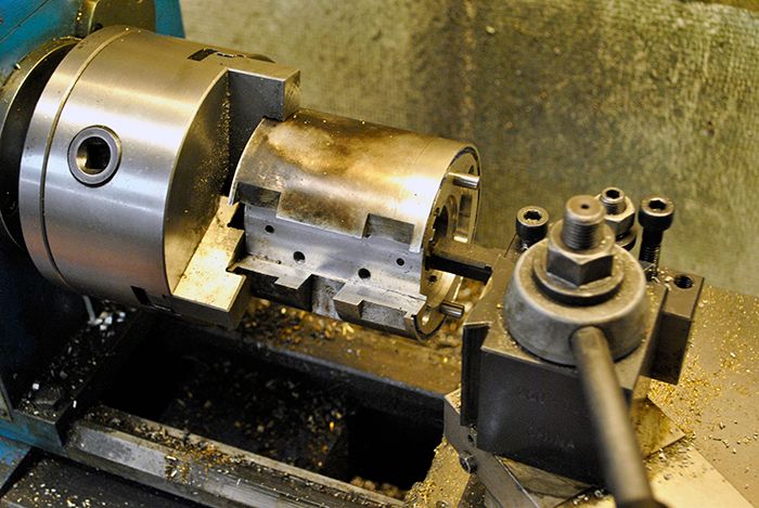 I made a groove around the journal bearing seats so the oil pressure acts on the whole bearing instead of just the top like before. 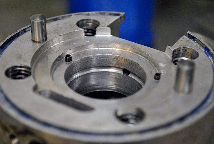 I also drilled a set of holes in the rear thrust washer to let oil in from the front journal bearing to the space between the washer and the thrust bearing, I shamelessly stole this idea from John who have experienced the same rotor drag as I. 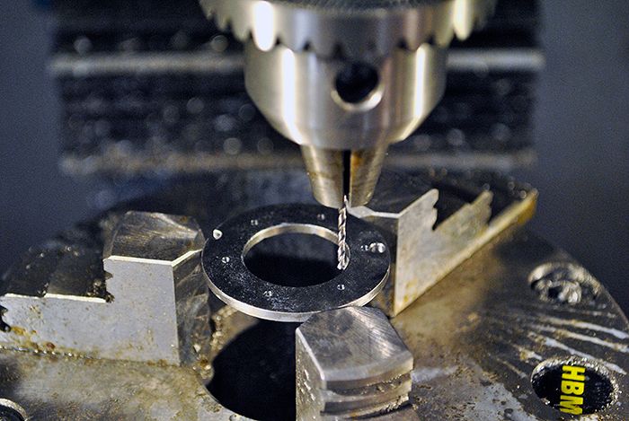 Here you can see some old wear marks in the washer from the thrust bearing, hopefully the new oil film will keep the two separated from now on. 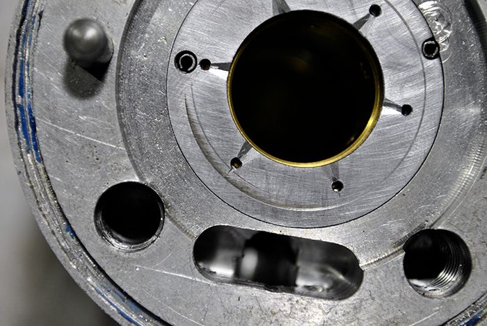 I did the usual propane flame test to see if any of the injectors were blocked, as you can see the one at 8 o´clock was partially clogged which might have messed with the combustion and increased the interstage temp reading. 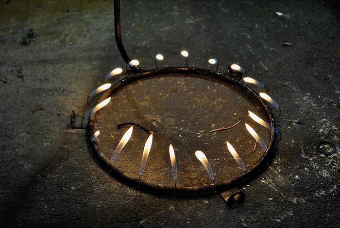 I just had to remove it and silver solder a new 0.7mm syringe injector in place, easy as ABC since I´ve done it a few times now... 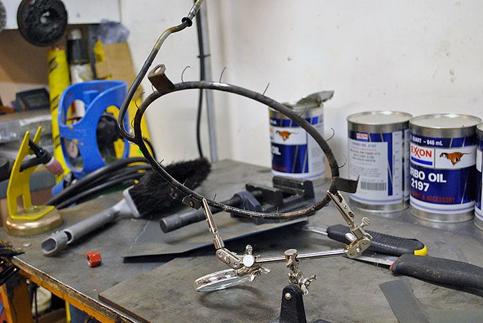 Close to midnight I had started to assemble the engine again before it was time to hit the bed, I removed the FOD damage marks on the diffusor wedges before assembling the compressor diffusor section. 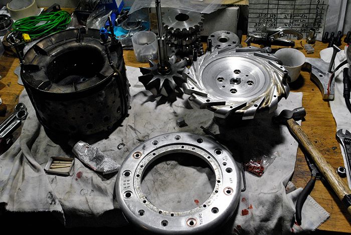 Cheers! /Anders |
|
Deleted
Joined: January 1970
Posts: 0
|
Post by Deleted on Sept 14, 2015 16:51:59 GMT -5
Hope it works and reduces the drag, you can then try the electric start :-) i have made some tweaks on mine :-)
All Best
|
|
|
|
Post by racket on Sept 14, 2015 20:52:15 GMT -5
Hi Anders
You've been busy :-)
How is the flametube looking, any hot spots , burnt bits, are evaps OK ?
Cheers
John
|
|
|
|
Post by Johansson on Sept 15, 2015 4:35:42 GMT -5
Hope it works and reduces the drag, you can then try the electric start :-) i have made some tweaks on mine :-) All Best I sure hopw so too, haven´t decided yet if I will save the starter for the JU-02 engine or fit it to this one. We´ll see how much spare time I have this winter. Hi Anders You've been busy :-) How is the flametube looking, any hot spots , burnt bits, are evaps OK ? Cheers John It is looking really good, no visible over heating and the evaporators look good with no signs of melting at the ends. |
|
|
|
Post by racket on Sept 15, 2015 16:18:02 GMT -5
Hi Anders
Excellent news, so we can use something similar for the JU-02 :-)
Cheers
John
|
|
|
|
Post by Johansson on Sept 16, 2015 1:41:56 GMT -5
Hi Anders Excellent news, so we can use something similar for the JU-02 :-) Cheers John I think so, the fact that the evaporators in regular 316 stainless are looking this good shows that the inconel ones you sent me should last a life time. :-) |
|
|
|
Post by Johansson on Sept 18, 2015 16:14:30 GMT -5
Today I put the engine together to try the bearing modifications out, I did everything properly just in case the rotor stricture issue would be solved. 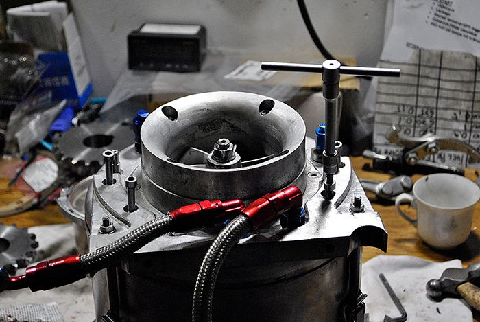 The test showed that the rotor still stiffens up when oil pressure is applied, the modifications were probably still useful in their own way but didn´t solve the stricture. I have an idea what might be the problem though, I´ll thing about it a bit and get back to you. 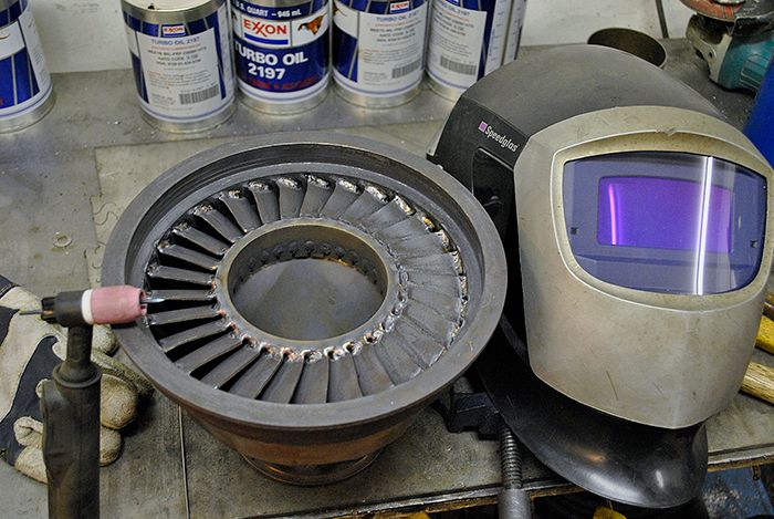 After that I straightened the broken freepower vanes and welded them in place, I added a bit more weld to the other vanes as well so they won´t crack again. 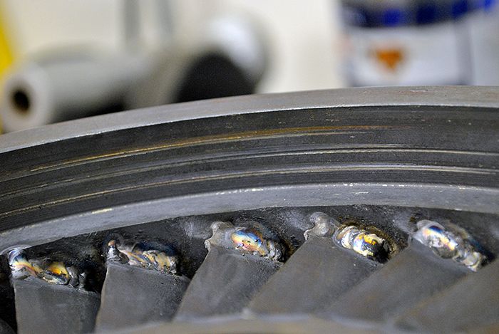 While welding the vanes I found these marks from the power turbine wheel rubbing the housing, it is most likely an old damage from the first test ride when the turbine shaft front bearing cage melted due to lack of cooling. 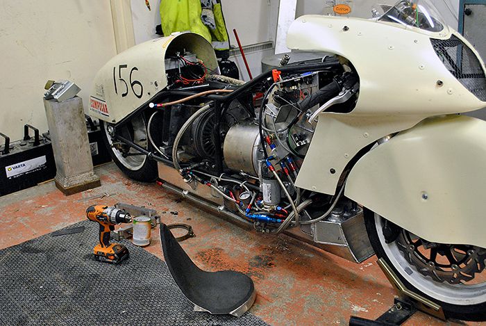 With the housing left to cool down I cut the seat apart and modified it to fit 10cm further back, this way I will get more room for my head behind the wind screen. 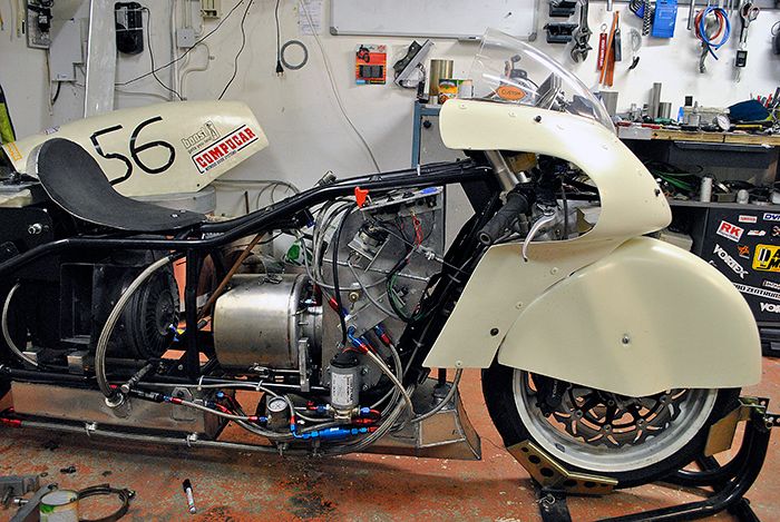 Cheers! /Anders |
|
|
|
Post by Johansson on Sept 20, 2015 16:24:55 GMT -5
FINALLY!!! I managed to solve the darn rotor stricture tonight! I grasped the last hay straw as we say here in Sweden and decided to secure the rear thrust washer that up until now has been loosely fitted in a recess. 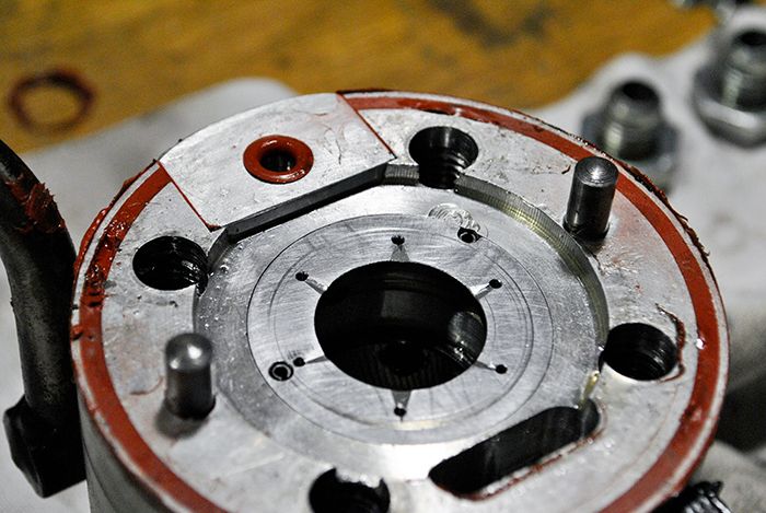 My guess was that the oil pressure applied on the journal bearing just behind the thrust washer would push it forward up against the axial bearing just like a hydraulic brake. I fitted four M4 screws to hold the washer in place. 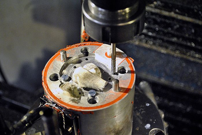 Here they are fitted, I assembled the engine and tested it with 5 kg oil pressure and the rotor spun almost as freely as without any oil pressure at all! Hooray! 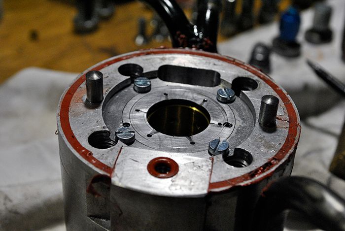 I am very glad to finally have solved this issue, now I won´t have to make the same mistake on the upcoming JU-02 engine. Cheers! /Anders |
|
Deleted
Joined: January 1970
Posts: 0
|
Post by Deleted on Sept 20, 2015 16:48:15 GMT -5
Nice....... best its a nice feeling knowing its sorted :-)
|
|


