rythmnbls
Veteran Member

Joined: August 2011
Posts: 145
|
Post by rythmnbls on Sept 20, 2015 16:48:38 GMT -5
Hopefully this mod will lower your temps with all that drag removed.
Steve.
|
|
|
|
Post by pitciblackscotland on Sept 20, 2015 17:28:26 GMT -5
Nice work Anders, I was hoping you could work this problem out. I can know start making some time to start working on the 10/106 engine that John ask me to finish off. Well done mate  Cheers, Mark. |
|
|
|
Post by racket on Sept 20, 2015 18:44:00 GMT -5
Hi Anders
Thank you :-)
Now I know the 12/118 will be OK .
Cheers
John
|
|
|
|
Post by Johansson on Sept 21, 2015 4:09:00 GMT -5
Thanks guys!
I am very eager to start the bike and see how the idle temps behave, with that sort of rotor braking there must have been some increase in exhaust temps.
Cheers!
/Anders
|
|
|
|
Post by ernie wrenn on Sept 24, 2015 16:30:39 GMT -5
good job! Those problems are hard to find.
|
|
|
|
Post by racket on Sept 25, 2015 1:58:59 GMT -5
Hi Anders A few pics of the thrust bearing pocket in the 12/118    Front side  Cheers John |
|
|
|
Post by Johansson on Sept 25, 2015 2:43:24 GMT -5
Very smart design John! On my JU-01 I milled a recess behind the thrust washer which was a pain in the arse to get right, your way of doing it is much better. I´ll shamelessly copy it for the JU-02, thanks! |
|
|
|
Post by Johansson on Sept 30, 2015 16:34:48 GMT -5
This week I decided to make the water tank for the upcoming water injection system, a couple of evenings ago I made a styrofoam mockup to find the right size and shape for the tank. The idea is to make it double as a chest rest so I won´t have to hang all of my mighty 67kg´s on my arms... 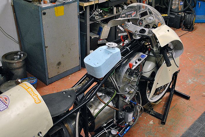 With the shape decided I started making the tank tonight in 1mm aluminum. 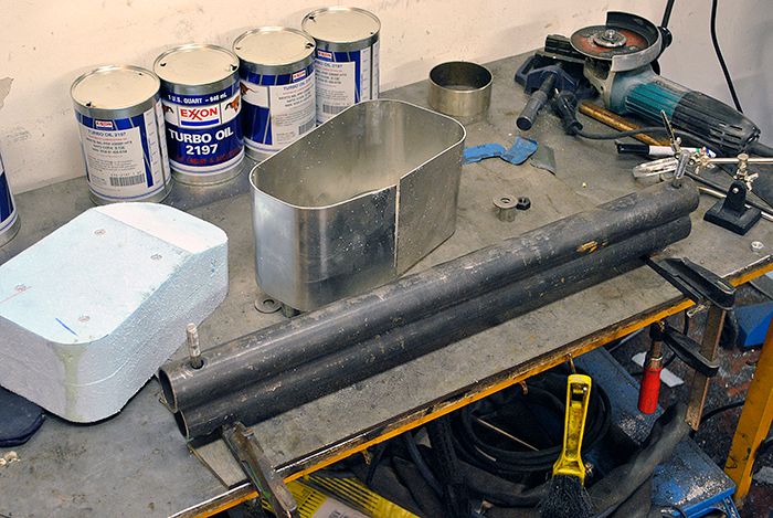 Not the best looking welds exactly, it would probably have helped if I had bothered to clean the oxide and dust from the aluminum before welding... 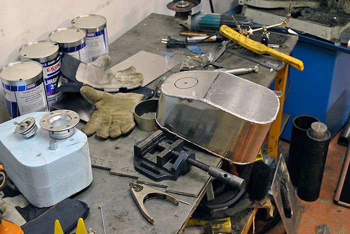 Oh well, it ended up leak free and that is all that matters. There is also a AN4 fitting welded to the bottom of the tank. 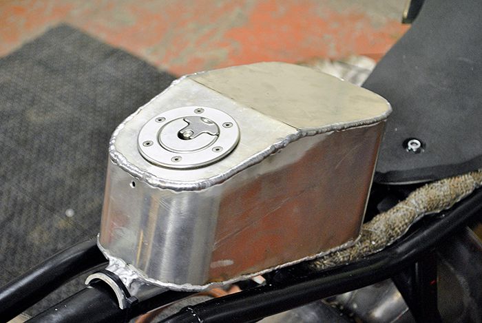 The result ended up the way I had pictured it, the water tank isn´t in the way for my helmet and with some padding on top I will have a nice rest for my arms while covering up behind the wind screen. 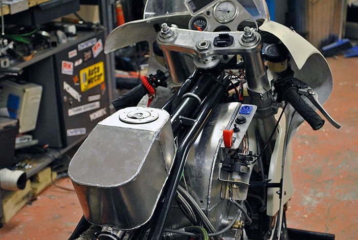 I ordered a water pump, pressure regulator and a high flow spray nozzle on Ebay last weekend so when I get it I can hook everything up and do some flow tests. Cheers! /Anders |
|
|
|
Post by Johansson on Oct 3, 2015 16:04:47 GMT -5
The exhaust pipes on the bike have been less than perfect, they aimed the exhaust jet straight out from the sides which probably caused lots of extra drag. Time to do something about it. 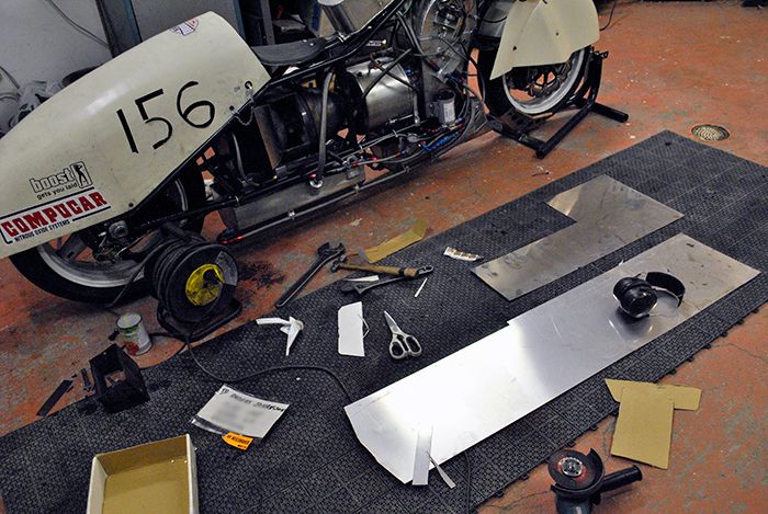 I´ve just started to make the new extensions, they are meant to angle the exhaust backwards and have an increasing cross section to increase the flow through them. Even the smallest decrease in back pressure for the freepower turbine adds horsepower. 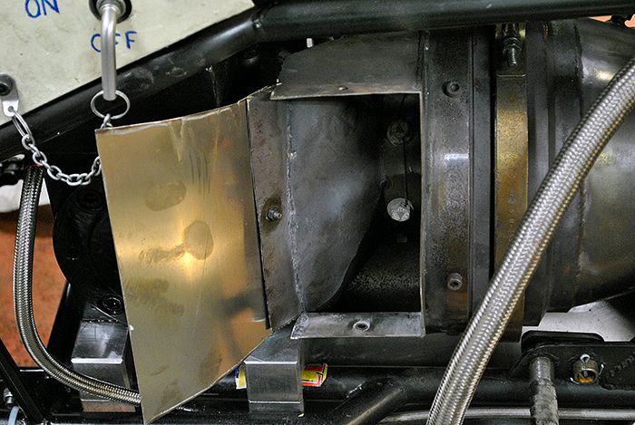 After an hour and a half I had one side ready to be spot welded together, the exhausts stick out just as far as my leg so they won´t cause any extra drag. 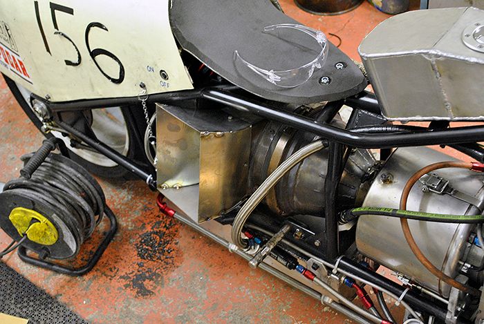 Here you can imagine just how much better the flow will be, now it can leave the power turbine in a much straighter line than before. 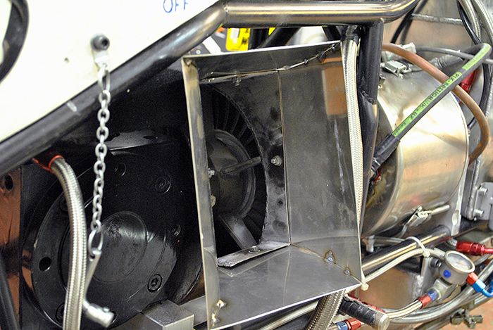 Cheers! /Anders |
|
gidge348
Senior Member
Joined: September 2010
Posts: 426 
|
Post by gidge348 on Oct 3, 2015 19:27:31 GMT -5
Hi Anders, I went through some this with Woody, the aero guy that is helping me with the Nimbus streamliner. I have been trying to find his notes on what he said about turbine exhaust positioning to decrease back pressure & will load them up when I find them. I do have some of the CFD's to do with the exhaust influences on the body that may be of interest. Firstly we had the standard Nimbus exhaust poking out of the body work.  Then because we were chasing the minimum of frontal area (under 6sq feet)for the car we trimmed them in line with the body  Then ran flow simulation.  Nothing weird here so ran another with the car in yaw.  Once again all ok no major separation or weird stuff going on. Pointing the exhaust sideways would not really have been a problem. Apparently air is fine getting pushed apart but is not as happy when it needs to come back together and that is what we were looking at. Most of our messing around was using the exhaust to fill some of the void behind the car and make sure there was not any weird vortices or changes in pressure around the body that would cause instability. Have you thought of extending the exhausts all the way past the foot pegs??? May save you getting a hot foot, plus poke the exhaust into the void behind??? Cheers Ian... |
|
|
|
Post by Johansson on Oct 4, 2015 0:09:08 GMT -5
Hi Ian, Nice looking flow simulatons! Are you sure that a jet exhaust pointing 90° out the sides wouldn´t have upset the air flow over the bike? It feels like it would keep the air from flowing smoothly past the tail and fill the void behind it. The foot pegs are in front of the exhausts already, in one of the pics the handle for the electrical cord coil looks like it belongs to the bike so it might have fooled you. Cheers! /Anders |
|
gidge348
Senior Member
Joined: September 2010
Posts: 426
|
Post by gidge348 on Oct 4, 2015 1:34:25 GMT -5
Hi Ian, Nice looking flow simulatons! Are you sure that a jet exhaust pointing 90° out the sides wouldn´t have upset the air flow over the bike? It feels like it would keep the air from flowing smoothly past the tail and fill the void behind it. Hi Anders, yes that is my understanding, this is another cut plot through the body  I remember seeing this and thinking wow, look at all that disturbance away from the body there must be a lot of wasted energy pushing all that air away but Woody said that is fine. Once it is out there its no problem, the problem with this was the vortices generated by no fairing on the wheels causing bad things to happen between the floor of the car and the ground. If you can get the air away from the body, that alone would not be a problem, but keeping the rest of it behaving itself is the issue. All this aero stuff scrambles my brain, nothing is as I thought it would be, it all depends on what you have and what issues the shape of the vehicle throws up. Like one of the reasons we went to filling in the void behind the car was help with the chute deployment, that is not an issue for you. The main thing that determines top speed seems to be frontal area..... boundary layers, vortices, pressure gradients and all that don't seem to affect top speed, but they can have affect stability etc. So anything you can do to reduce frontal area will have an good affect. Your bike seems pretty stable, not sure if you run in any cross winds or if it has any bad habits? cheers Ian... PS yep I tought the handle on the cord reel was the foot peg  |
|
|
|
Post by finiteparts on Oct 4, 2015 12:33:42 GMT -5
Hi Anders, I agree with your thinking on the exhaust. You would be hard pressed to find a turboprop out there that didn't turn the exhaust to point downstream at the exit. They do this for several reasons. The first reason is to recover the energy still in the exhaust stream and get whatever marginal thrust that they can from the jet exhaust. For most engines this is under 5% of the peak thrust, but why waste it if you can get a small bump for such a simple part. Second, the hot exhaust needs to be moved away from the aircraft structure. Aluminum's fatigue life is quickly reduced as it's temperature increases. Easily fixed with the exhaust stacks. A third reason is that there is a potential for backflow and thus a reduction in the effective area of the exhaust duct. When an flow is discharged out of an orifice normal to the mean flow path, there is a complicated vortical flow structure set up. www.efluids.com/efluids/gallery/gallery_images/EJICF2.jpgYou probably see this all the time during the Swedish winters...near posts, rocks, etc...  The local stagnation of the freestream flow sets up a horseshoe vortex that scrubs the wind facing side snow away from the base... The same thing happens to piers under bridges... chamani.iut.ac.ir/sites/chamani.iut.ac.ir/files//u120/scour_fig._3.jpgAnd of course, it also happens on gaseous jets in crossflows and leads to a lot of complex flow structures happening near the jet discharge.  So, when the holes are not completely circular and the pressure ratios are similar, the difference in relative momentum between the two flow is small and thus the freestream flow (blue arrows) can get pulled into the upstream side of the exhaust duct (yellow area) due to the presence of the horseshoe vortex. This forms a internal separation point (separation region shown in light blue) and thus the effective area of your exhaust duct is reduced.  Now, the wake caused by your leg being upstream of the exhaust duct may also cause the exit plane of the exhaust to be even more complex and potentially there may be a slight backpressure due to the higher static pressure of the stalled wake. The pressure ratio across your free turbine is sensitive to the exhaust duct downstream of it and having a complex flow near the discharge plane makes it really hard to figure out what the static pressure will be...you can't just assume that it will be the freestream static pressure because there are all kinds of things happening near it. I think what you have done will only help your performance...the only suggestion that I would have made was to have it discharge in a nearly axial direction because the cross-stream component does absolutely nothing for your performance. If the area of the duct was large enough, it should not impact your backpressure significantly to continue the turning a bit longer to get it axial. Good luck! Chris |
|
|
|
Post by Johansson on Oct 5, 2015 3:58:37 GMT -5
Hi Ian, Nice looking flow simulatons! Are you sure that a jet exhaust pointing 90° out the sides wouldn´t have upset the air flow over the bike? It feels like it would keep the air from flowing smoothly past the tail and fill the void behind it. Hi Anders, yes that is my understanding, this is another cut plot through the body I remember seeing this and thinking wow, look at all that disturbance away from the body there must be a lot of wasted energy pushing all that air away but Woody said that is fine. Once it is out there its no problem, the problem with this was the vortices generated by no fairing on the wheels causing bad things to happen between the floor of the car and the ground. If you can get the air away from the body, that alone would not be a problem, but keeping the rest of it behaving itself is the issue. All this aero stuff scrambles my brain, nothing is as I thought it would be, it all depends on what you have and what issues the shape of the vehicle throws up. Like one of the reasons we went to filling in the void behind the car was help with the chute deployment, that is not an issue for you. The main thing that determines top speed seems to be frontal area..... boundary layers, vortices, pressure gradients and all that don't seem to affect top speed, but they can have affect stability etc. So anything you can do to reduce frontal area will have an good affect. Your bike seems pretty stable, not sure if you run in any cross winds or if it has any bad habits? cheers Ian... PS yep I tought the handle on the cord reel was the foot peg Hi Ian, This aerodynamic stuff is just like trying to predict how a combustor will work, the old "if it looks right it is right" rule doesen´t really apply... The good thing is that small frontal area is what this bike is all about, so even with the pumps and hoses sticking out on the sides it might be a pretty slick design. I will close the hole behind the rear wheel and add some skirts from the exhaust pipes and backwards to keep air from the rear wheel, I´ve read that the spokes act as a fan so the less air passing through it the better. /Anders |
|
|
|
Post by Johansson on Oct 5, 2015 4:56:40 GMT -5
Hi Anders, I agree with your thinking on the exhaust. You would be hard pressed to find a turboprop out there that didn't turn the exhaust to point downstream at the exit. They do this for several reasons. The first reason is to recover the energy still in the exhaust stream and get whatever marginal thrust that they can from the jet exhaust. For most engines this is under 5% of the peak thrust, but why waste it if you can get a small bump for such a simple part. Second, the hot exhaust needs to be moved away from the aircraft structure. Aluminum's fatigue life is quickly reduced as it's temperature increases. Easily fixed with the exhaust stacks. A third reason is that there is a potential for backflow and thus a reduction in the effective area of the exhaust duct. When an flow is discharged out of an orifice normal to the mean flow path, there is a complicated vortical flow structure set up. www.efluids.com/efluids/gallery/gallery_images/EJICF2.jpgYou probably see this all the time during the Swedish winters...near posts, rocks, etc... The local stagnation of the freestream flow sets up a horseshoe vortex that scrubs the wind facing side snow away from the base... The same thing happens to piers under bridges... chamani.iut.ac.ir/sites/chamani.iut.ac.ir/files//u120/scour_fig._3.jpgAnd of course, it also happens on gaseous jets in crossflows and leads to a lot of complex flow structures happening near the jet discharge. So, when the holes are not completely circular and the pressure ratios are similar, the difference in relative momentum between the two flow is small and thus the freestream flow (blue arrows) can get pulled into the upstream side of the exhaust duct (yellow area) due to the presence of the horseshoe vortex. This forms a internal separation point (separation region shown in light blue) and thus the effective area of your exhaust duct is reduced. Now, the wake caused by your leg being upstream of the exhaust duct may also cause the exit plane of the exhaust to be even more complex and potentially there may be a slight backpressure due to the higher static pressure of the stalled wake. The pressure ratio across your free turbine is sensitive to the exhaust duct downstream of it and having a complex flow near the discharge plane makes it really hard to figure out what the static pressure will be...you can't just assume that it will be the freestream static pressure because there are all kinds of things happening near it. I think what you have done will only help your performance...the only suggestion that I would have made was to have it discharge in a nearly axial direction because the cross-stream component does absolutely nothing for your performance. If the area of the duct was large enough, it should not impact your backpressure significantly to continue the turning a bit longer to get it axial. Good luck! Chris Hi Chris, Good to hear that you think I am on the right track, if I had more resources I would get the whole bike with me on it 3D scanned and run through a CDF program to find out what needs to be done but until then good advice and lots of reading will have to do. That snow pattern behind trees and stones is very common in the winter, I have tipped down into such a hole more than once with a snowmobile while freeriding in the hills. Angling the exhaust even more backwards can be done, I´ll try this setup first now that it is made and later when I have the speed and engine numbers I can add extensions and see if they make any difference. Thanks! /Anders |
|


