|
|
Post by racket on Apr 2, 2017 17:04:28 GMT -5
Hi Anders
Nice test stand , love those engine mounts :-)
Just something you might need to consider ...............
With your load cell positioning , unless its axially in line with the engine shaft we create a "leverage moment ??" that might require the test stand to be "calibrated" so that accurate/reliable readings are obtained.
When I did my testing of the TV84 engine I suspended the whole bike and engine by chain and had the pair of matched spring balances mounted one each side of the jet nozzle .
You'll be able to calibrate by pushing a set of bathroom scales against your jet nozzle and read off the corresponding load cell numbers .
She's getting close to finally being together , have you fitted an air deflector at the front of the flametube to force air down the back of the diffuser wall and into the inner wall holes ??
Cheers
John
|
|
|
|
Post by Johansson on Apr 3, 2017 1:21:25 GMT -5
Hi John, Good pointer about the load cell calibration, I´ll make sure to do that. I haven´t decided what to do about the air deflector yet. I am sort of allergic to solving problems I don´t know if they even exist, but I know you you have good experience with them and JU-01 apparently works even if I haven´t run it without the deflector so I really don´t know how much higher the core temps would be without one. Still, it is a quick job to add one so perhaps I should do it just to avoid the risk of an overheated inner liner. Decisions decisions...  Cheers! /Anders |
|
|
|
Post by racket on Apr 3, 2017 1:35:36 GMT -5
|
|
|
|
Post by Johansson on Apr 3, 2017 2:36:42 GMT -5
|
|
ripp
Veteran Member
 I'm sorry, I don't speak english, so I torment you (and myself) with a translation program,Sorry
Joined: January 2013
Posts: 230
|
Post by ripp on Apr 3, 2017 3:03:56 GMT -5
Hi John, I'm pretty sure your problem with the combustion chamber had a different cause than too little cooling.  The air is thus directed inwards. I only think about the inside edge. An inspection after the first test run will show if the material has heat damage Cheers Ralph translate.google |
|
|
|
Post by racket on Apr 3, 2017 4:19:07 GMT -5
Hi Ralph
The first run might be its last run :-(
It wasn't cooling that caused my flametube failure , it was much more complex , the flametube "exploded" outwards due to a lower static pressure between FT inner wall and shaft tunnel than what was inside the flametube , the flame exited the flametube , melted the shaft tunnel heat protector steel shroud and its ceramic blanket before travelling forward and up the back wall of the diffuser .
The air deflectors cured the problem by establishing the correct pressure balance , there are differences between a radial inflow turbine and an axial turb that radially changes potential static pressures within the flametube due to the differing radial positions that the gases exit the flametube , radial wheels require the gases to exit at the periphery whereas axial wheels have the gases exiting the flametube closer to the shaft tunnel .
Anders and my engines differ from conventional RC turbine engines , we have have very short flametubes in relatively large diameter engines , the FT length/diameter ratio isn't favourable , we also have to reduce axial space for air movement between flametube and diffuser to the bare minimum which again calls for compromises .
I'd be only too happy to see Anders engine work without air deflectors , as I would my own , but it gets to be an expensive exercise if the flametube fails :-(
Cheers
John
|
|
ripp
Veteran Member
I'm sorry, I don't speak english, so I torment you (and myself) with a translation program,Sorry
Joined: January 2013
Posts: 230
|
Post by ripp on Apr 3, 2017 7:28:06 GMT -5
Hi John, I hope to have understood everything correctly (you know I speak unfortunately no english, And the google translater is not easy to understand). I can not comprehend that. A gas turbine engine is an open system. The compressed air after the diffusor and the pressure is overall in the engine (the ngv and the turbine are properly dimensioned, whether radial or axial turbines). You can check the pressure at the tertiary holes with a thin copper tube (I had already mentioned). Here my phoenix 30.3. It has a narrowing over the shaft tunnel. By the too large tertiary holes, no real pressure could build up in the sticks and a correct evaporation would occur. The result is       Cheers Ralph translate.google |
|
|
|
Post by Johansson on Apr 3, 2017 14:13:20 GMT -5
Hi John and Ralph, Please continue the discussion about this, it is very interesting to read. I´ll stay out of it though. I checked the engine out just now and it looks like a straight strip of sheet stainless 16mm wide will split the air diffuser exits neatly in half. 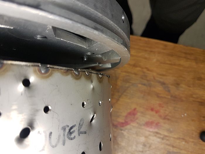 Cheers! /Anders |
|
marvnero
Member
Joined: February 2017
Posts: 33 
|
Post by marvnero on Apr 3, 2017 17:19:46 GMT -5
Hi Anders,
I finally had the time to read this thread completely and I have to tell you that your craftsmanship is just incredible!
There are a lot of hints and tips how to manufacture the different parts of a turbine engine. Thanks for sharing your knowledge in such a detailed way!
Keep up the good work!
Cheers,
Marvin
|
|
|
|
Post by racket on Apr 3, 2017 23:04:58 GMT -5
Hi Ralph
I generally design the minimum passageway area at 1.5 times the hole area downstream , so in your engine where it narrows near the rear of the shaft tunnel , that area would be 1.5 times the main dilution hole area plus the stick bore area .
With your diffuser exit axial vanes , the air exiting them will still have some swirl component , as does the air exiting my and Anders diffusers , when that air tries to travel inwards towards the shaft tunnel that swirl velocity increases and the static pressure drops as the air obeys the Laws of Physics .
If the static pressure drop is too great then air flow into the inner wall area is effectively stopped as the static pressure within the flametube is equal to the static pressure between shaft tunnel and inner wall , it doesn't take much of a static pressure drop as we hopefully only have a 5% pressure drop across the flametube wall .
I'm not the first to use air deflectors , there was info on the Net many years ago from a guy making a RC turbine engine who experienced high temps at the turb bearing area of his shaft tunnel and flametube inner , he fitted an air deflector and it cured his problems .
Cheers
John
|
|
|
|
Post by Johansson on Apr 4, 2017 7:25:51 GMT -5
Hi Anders, I finally had the time to read this thread completely and I have to tell you that your craftsmanship is just incredible! There are a lot of hints and tips how to manufacture the different parts of a turbine engine. Thanks for sharing your knowledge in such a detailed way! Keep up the good work! Cheers, Marvin Thank you very much Marvin! |
|
|
|
Post by Johansson on Apr 4, 2017 15:34:00 GMT -5
After the failed test start of the bike I rolled a strip of stainless sheet for the JU-02 air deflector. 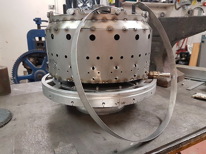 Here I have welded it in place, it neatly divides the air exiting the diffuser and sends an estimated 1/3rd of the air towards the inner combustor liner. 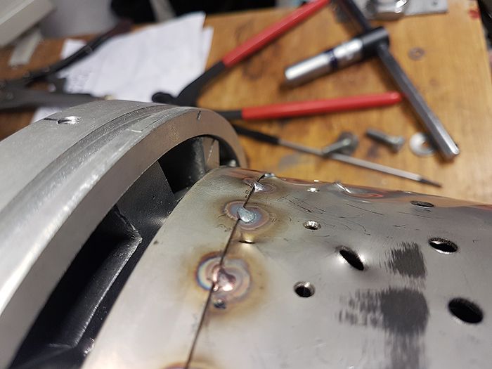 I also got a parcel with the stainless screws I ordered a couple of days ago, very quick delivery from UK. 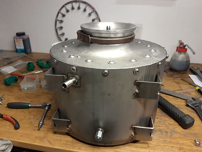 As you can see the engine is almost completely assembled for its maiden run, I haven´t fitted the fuel injectors and there is some work left to do with the test stand before that. Now that the engine isn´t spread all over the work bench I will give the turbofan build some attention but it isn´t long before JU-02 is ready to rumble!  Cheers! /Anders |
|
|
|
Post by racket on Apr 4, 2017 16:59:31 GMT -5
Hi Anders
Ready for action :-)
Cheers
John
|
|
|
|
Post by Johansson on Apr 9, 2017 15:08:32 GMT -5
With JU-01 taken out of the bike chassis I had the opportunity to test fit JU-02 to see if the feet are spaced apart properly and how close to the fuel tank the oil return fitting will sit. And of course to see what it will look like. Old JU-01 engine installed: 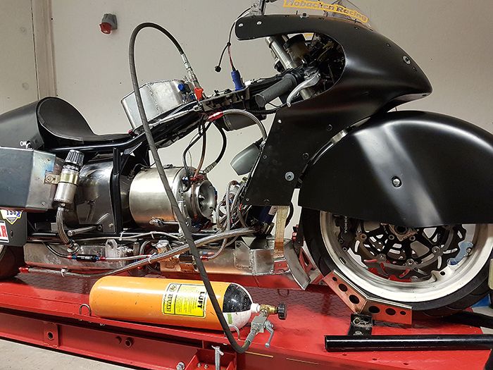 New JU-02 test fitted, it sure fills out the chassis better. 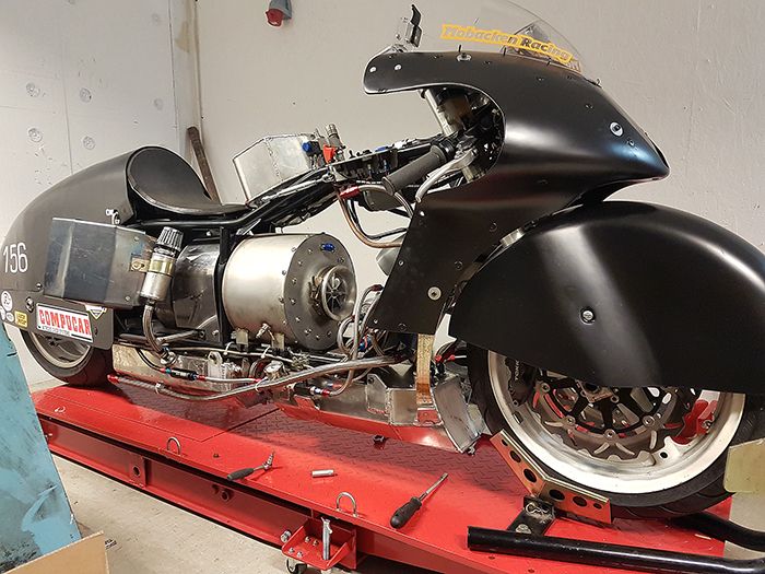 Oh yes. 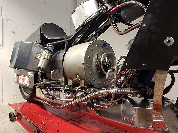 Other side: 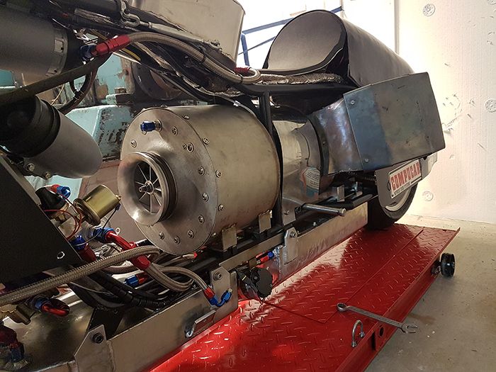 To sum this up I can´t wait until I can install JU-02 in the bike and grab a handful of throttle! Cheers! /Anders |
|
|
|
Post by racket on Apr 9, 2017 16:14:45 GMT -5
Hi Anders
LOL............just hook up the plumbing ;-)
Cheers
John
|
|


