|
|
Post by racket on Nov 20, 2017 19:44:34 GMT -5
Hi Tony
10 lbs/sec at ~6 psi , it'll be needing ~200 hp to drive it .
Cheers
John
|
|
CH3NO2
Senior Member

Joined: March 2017
Posts: 455 
|
Post by CH3NO2 on Nov 20, 2017 21:45:54 GMT -5
Hi John, WOW! That'll be insane. What do you think the HP of the gas flow will be at Lambda 1? What will be the chamber and throat diameters? Radiation cooled, lined or boundary layer coolant? I can just imagine the energy release from all that air at full afterburn. Gotta make sure the sled stays firmly on the ground.  |
|
CH3NO2
Senior Member
Joined: March 2017
Posts: 455
|
Post by CH3NO2 on Nov 20, 2017 21:53:29 GMT -5
I'm afraid to ask how much thrust it will make...
|
|
|
|
Post by racket on Nov 20, 2017 22:57:49 GMT -5
Hi Tony
Thrust should be the sunny side of 500 lbs
Cheers
John
|
|
Sweetenough
Veteran Member
Joined: April 2016
Posts: 121
|
Post by Sweetenough on Nov 21, 2017 3:27:45 GMT -5
Nice! Are you planning go use somekind of guide vane? Or is that just overkill?
|
|
|
|
Post by Johansson on Nov 21, 2017 5:55:49 GMT -5
The sound of the turbofan at full reheat will be interesting for sure, since the fan is producing a very low pressure air flow there won´t be the normal afterburner scream but rather a loud rumbling. Add to that the whine from the turbofan and turbine plus the two gas producers running at 2+ bar P2 and the amount of noice coming from the ice yacht will be awesome.  |
|
|
|
Post by Johansson on Nov 21, 2017 6:01:34 GMT -5
Nice! Are you planning go use somekind of guide vane? Or is that just overkill? Do you mean inlet guide vanes or vanes downstream the fan? In front of the fan I will add a large bellmouth, I haven´t really figured out how to make the transition between the fan and the afterburner yet. All I know is that we need some kind of sliding fit so no stress from the AB is transmitted to the fan cover. Most likely we´ll use a graphite rope to seal the sliding parts so it can take the heat soak after a run. |
|
Sweetenough
Veteran Member
Joined: April 2016
Posts: 121
|
Post by Sweetenough on Nov 21, 2017 7:13:51 GMT -5
Sorry, forgot the "inlet" in guide vane. Have no idea if it is necessary or not. I was just curious....
|
|
|
|
Post by Johansson on Nov 21, 2017 7:21:53 GMT -5
Sorry, forgot the "inlet" in guide vane. Have no idea if it is necessary or not. I was just curious.... I am a bit short on space in front of the fan, there will be an exhaust scroll that takes up most of the room between the two wheels. I´ll just have room for the bellmouth and the engine mount. About the exhaust scroll, I have finally decided to throw away the brick shaped one I made earlier and make a new one that has a better entry angle for the two inlet ports. I am trying to figure out how to best design it and will hopefully start building it soon. |
|
CH3NO2
Senior Member
Joined: March 2017
Posts: 455
|
Post by CH3NO2 on Nov 21, 2017 7:44:53 GMT -5
Hi Anders, If your transition is a diffuser and it must also be a slip fit, you may be able to use any leakage (IE bleed) to your advantage to increase chamber pressure and reduce length.  |
|
Sweetenough
Veteran Member
Joined: April 2016
Posts: 121
|
Post by Sweetenough on Nov 21, 2017 8:11:32 GMT -5
Thanks Anders. Looking forward to follow the build!
|
|
|
|
Post by Johansson on Nov 23, 2017 17:19:41 GMT -5
Hi Anders, If your transition is a diffuser and it must also be a slip fit, you may be able to use any leakage (IE bleed) to your advantage to increase chamber pressure and reduce length. I am not sure I understand that picture, what is the bleed air for? Anyway, the reason for the slip joint is to free the fan cover from any kind of directional stress so I think a simple heat proof gasket of sort inside a slip joint will do.  I welded up the exhaust manifold tonight, I know I said that I would make a better looking manifold but after giving it some thought I decided to stick with this one for now. It is difficult to make a proper one with the space limitations and since we hope to have the ice yacht ready to run for Speed Weekend (a long shot but might be doable) this one will have to do. 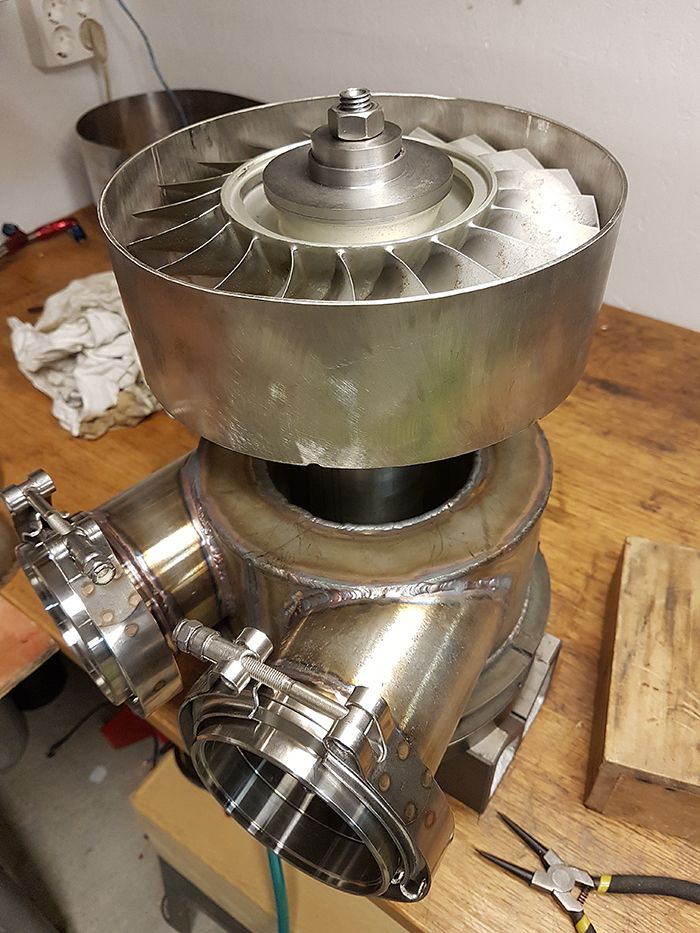 My biggest concern is that since we start one gas producer at a time the first one might blow exhaust gasses up into the second one making it difficult to start, but if that is the case we just have to figure out a way to start them both at the same time. Cheers! /Anders |
|
marvnero
Member
Joined: February 2017
Posts: 33
|
Post by marvnero on Nov 23, 2017 18:42:54 GMT -5
Hi Anders,
Even If I'm not as far into my twin turbine project as you are in yours, I spend quite some time thinking about how to start both turbines without the turbine startet first blowing exhaust gases into the one to start second.
I came up with two ideas to counteract that.
1) A bleed valve right behind the junction of the two exhaust streams. Before starting the first you open the bleedvalve relieving almost any positiv positiv pressure from the junction. It is even possible that you get a static pressure below ambient in the exhaust port of the second turbine as the exhaust gases from the first turbine are rushing past the junction. This is the method I'd prefer.
2) A butterfly valve in the connection of the turbine you`d like to start second and the junction of the two exhaust streams.
I hope my ideas help you finding a solution!
Cheers,
Marvin
|
|
CH3NO2
Senior Member
Joined: March 2017
Posts: 455
|
Post by CH3NO2 on Nov 23, 2017 23:23:55 GMT -5
Hi Anders, If your transition is a diffuser and it must also be a slip fit, you may be able to use any leakage (IE bleed) to your advantage to increase chamber pressure and reduce length. I am not sure I understand that picture, what is the bleed air for? Anyway, the reason for the slip joint is to free the fan cover from any kind of directional stress so I think a simple heat proof gasket of sort inside a slip joint will do. I welded up the exhaust manifold tonight, I know I said that I would make a better looking manifold but after giving it some thought I decided to stick with this one for now. It is difficult to make a proper one with the space limitations and since we hope to have the ice yacht ready to run for Speed Weekend (a long shot but might be doable) this one will have to do. My biggest concern is that since we start one gas producer at a time the first one might blow exhaust gasses up into the second one making it difficult to start, but if that is the case we just have to figure out a way to start them both at the same time. Cheers! /Anders Beautiful work Anders. How did you cut your primary tubes to conform to the main chamber curvature? That's no small task.l The drawing I attached above is a hybrid diffuser. Its a way to make a diffuser much shorter and with higher pressure recovery (IE for more thrust). Diffusers are a topic covered in Arthur Lefebevers book "Gas turbine combustion." Many different types of diffusers are discussed. And you will probably want some kind of diffuser before your afterburner. With the particular hybrid diffuser I cited above is a kind that uses ~2-8% leakage (bleed) as a way to diffuse the flow more rapidly and in a shorter distance. If you have a slip fit that leaks a little, you could use that leakage to your advantage. As for starting two manifolded turbines at once, I can see how that could be a challenge. However you may be able to use a couple of these exhaust valves to create a switchable bypass from the turbine manifold. There are a couple of different ways they could be integrated to help with starting. One valve for pressure relief or two valves for pressure relief with decouplinng. Tony www.amazon.com/Loudvalves-Activated-Exhaust-Cutout-stainless/dp/B06XDWD9WN/ref=sr_1_2?s=automotive&ie=UTF8&qid=1511495771&sr=1-2&keywords=4%22+Boost+Activated+Exhaust+Cutout |
|
|
|
Post by Johansson on Nov 24, 2017 17:55:23 GMT -5
WTF have you done Olov?? We were supposed to just bring a pile of crap to the race, drink beer and talk about how fast we will go next year! 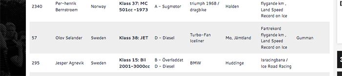 |
|