nersut
Veteran Member
  
Joined: September 2012
Posts: 223
|
Post by nersut on Sept 20, 2012 3:00:27 GMT -5
Hi John I was hoping that I could reuse some of the existing metals. But okay I can see it now, it will be messy. I made some sketches again with flame holder in 4.5 in & about 11 in i length. Don't mind the square holes. ;D Just a sketch. I am not sure if there should be a gab between the flame holder & the turbine inlet. Which one is the correct one? Without gab. 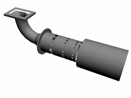 Or with a gab 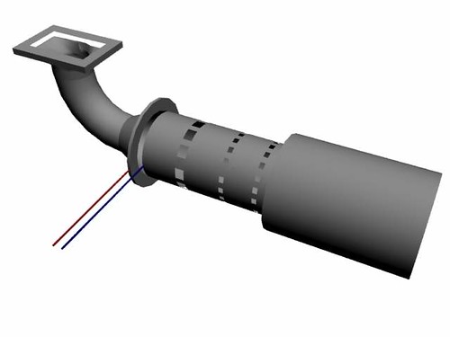 If there should be a gab, how much should there be? Cheers Erik |
|
|
|
Post by racket on Sept 20, 2012 4:34:21 GMT -5
Hi Erik
No gap , all air through the flametube holes .
You will need some sort of slipjoint to allow for differential expansion between flametube and outer can
Cheers
John
|
|
nersut
Veteran Member
  
Joined: September 2012
Posts: 223
|
Post by nersut on Sept 20, 2012 9:05:29 GMT -5
Hi John Super, no gab then. I was looking at Don Giandomenico's GR-1 Combustor Formula at www.rcdon.com/html/gr-1_turbojet_project_3_8_04.html where he mentioned that there should be a bypass section for extra cooling.  I will try to gather some stainless steel tubing today. Cheers Erik |
|
|
|
Post by racket on Sept 20, 2012 15:34:30 GMT -5
Hi Erik
Gaps are old technology as its impossible to know what the gap will be at running conditions when expansion of the various parts has taken place , put all air thru the FT wall holes .
Don does beautiful construction work and his Site is a great source of information for making the bits , I'd recommend it to anyone , but some of the turbine theory is a bit suspect as its been sourced from unreliable sources .
I generally have my slip joint at the outlet end of the FT , there can be several millimetres of axial expansion with a stainless flametube .
Cheers
John
|
|
nersut
Veteran Member
  
Joined: September 2012
Posts: 223
|
Post by nersut on Sept 21, 2012 6:02:14 GMT -5
Hi John Okay, I will make my new flame-tube without a gab but make some sort of expansion joint. And I am considering to make the combustor without the elbow, just strait on the turbo flange. I am not sure about the length required for the flame-tube. Any idea? I will be using the same high pressure fuel nozzle I used before. The reason is that it atomizes the fuel very well, even with the undersized flame-tube (7.5 in long 2,5 in diameter) I used and no evaporator-tubes, it burned all of the diesel before exiting (no flames at the turbine wheel except when starting up with too much fuel)  I found some stainless tubes (11.5 in diameter) yesterday that I am going to cut & roll to 4.5 in for the flame-tube. Cheers Erik |
|
nersut
Veteran Member
  
Joined: September 2012
Posts: 223
|
Post by nersut on Sept 21, 2012 22:49:56 GMT -5
Update Today I made some flanges for the new combustor. The new dimensions are: - Combustor length: 35.5 cm (14 in)
- Combustor diameter: 15.5 cm (6.1 in)
- Flame-holder diameter: 11.5 cm (4.5 in)
- Primary area: 36 holes x 6 mm
- Secondary area: 8 holes x 10 mm
- Tertiary area: 8 holes x 16 mm
The raw flanges 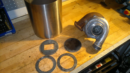 Turbo flange 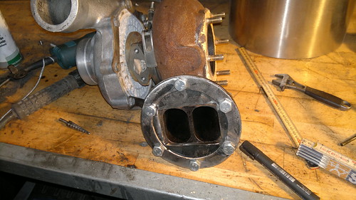 Flame-tube hole markups 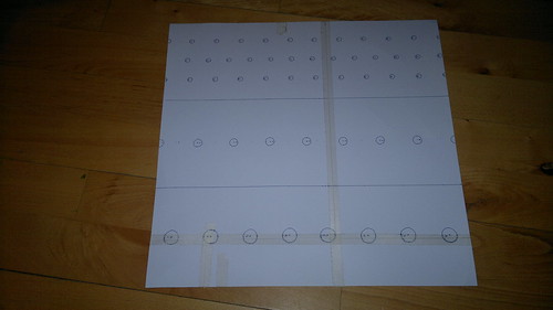 Combustor markup 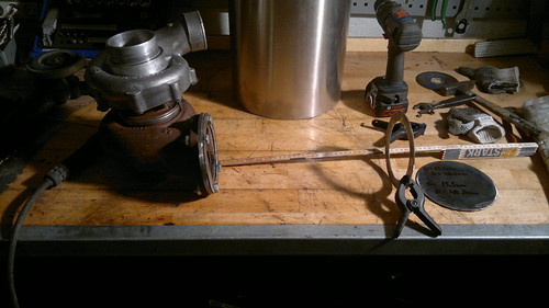 Tomorrow I will cut & roll the stainless tube for the combustor & the flame-tube & drill the holes. I have some glowplugs from a old toyota diesel engine. Are automotive glowplugs good as ignition source for gas turbines? Pros/Cons? I will call this turbocharger based gas turbine: FJK-2! ;D Cheers Erik |
|
nersut
Veteran Member
  
Joined: September 2012
Posts: 223
|
Post by nersut on Sept 23, 2012 20:20:32 GMT -5
Update - Flame-holder build. Hi, today I began to build the new flame-holder for the FJK-2. Marking up for the holes 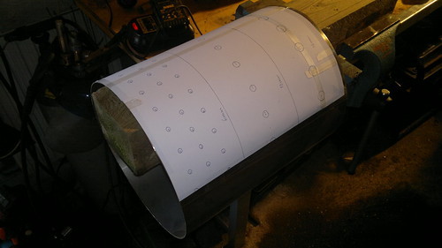 Data: - Primary:
- 1. row: 11 x 5,0 mm
- 2. row: 13 x 6,0 mm
- 3. row: 11 x 6,0 mm
- 4. row: 22 x 1,5 mm (film cooling holes)
- Secondary:
- 5. row: 8 x 10,0 mm
- 6. row: 21 x 1,5 mm (film cooling holes)
- Tertiary:
- 7. row: 8 x 16,0 mm
Actual total hole area: 32,07cm2 JetSpecs recommended: 32,42cm2, pretty close only 1 % off.  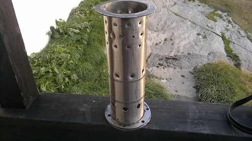 The holes are flared for better flow 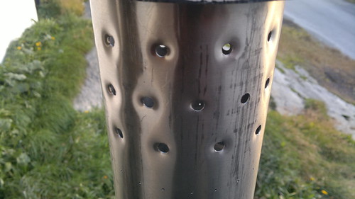 Inside view with fuel nozzle test fitted 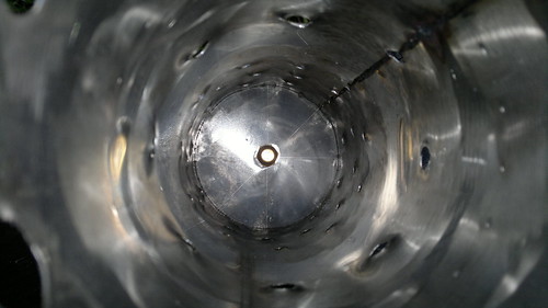 Flame-holder test fitted to the turbocharger 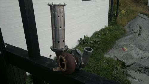 The flame-holder still needs to be welded together & the end has not been tapered yet to fit the turbine inlet. Cheers Erik |
|
|
|
Post by racket on Sept 25, 2012 4:34:57 GMT -5
Hi Erik
May I suggest you open up 4 of the 6mm holes in the 3rd row to 10mm diameter so as to provide some deeper penetrating air jets that will hopefully get to the centre of the flametube/fuel spray, those 6mm holes won't penetrate far enough.
What spray pattern is your spray nozzle ??
A hollow cone pattern will/should promote more stable combustion due to recirculation of flame back into the "hollow" in the centre of the spray .
Cheers
John
|
|
nersut
Veteran Member
  
Joined: September 2012
Posts: 223
|
Post by nersut on Sept 25, 2012 10:22:40 GMT -5
Hi John
I will follow your suggestion with the larger holes on the 3rd row.
I am using a Monarch 7.5 gph 60° spray angle I think it is a PLP - which is Semi-Solid-Cone pattern or a PL - Hollow-Cone pattern.
I am not sure, but I will check it.
I used the 7.5 gph@100 psi for the FJK-1 and I am probably going to use a bigger nozzle for the FJK-2.
I have a Monarch 9.5 gph@100 psi laying on the shelf.
My fuel pump can be regulated from 0 to 200 psi.
The Garrett TA5051 Turbocharger's flow characteristics is similar or between a Garrett GT40 & GT42.
Do you have any suggestions for the nozzle flow size for the FJK-2?
Cheers
Erik
|
|
|
|
Post by racket on Sept 25, 2012 16:21:51 GMT -5
Hi Eric
With a ~2.5" inducer you should be flowing ~1 lb/sec of air so ~1 lb/min -60 lbs/hour of fuel, thats ~9 US GPH of kero .
There are "variables", notably the turbine stage size , that will influence the air flow and consequently the fuel flow.
I'd start with the same 7.5 GPH nozzle you're currently using , this should provide a bit of a safety factor in case something goes wrong in those first few spoolups , once you've established that the 7.5 nozzle can't provide sufficient fuel for full bore power you can then "safely??" increase the nozzle size by an appropriate amount .
We need to remember that the nozzles are generally rated at 100 psi fuel pressure, but that assumes the spray is into ambiant air pressures not a P2 pressure which limits the actual pressure drop across the nozzle .
Assuming a P2 of 30 psi and a fuel pressure of 100 psi , the actual pressure drop is only 70 psi , and as flow is at the sq root of pressure you'd only be flowing ~ 84% of its rated flow , so a 10 GPH nozzle would only be flowing like an 8.4GPH .
If you used your 7.5 GPH nozzle at 200 psi delivery pressure (170 psi pressure drop at 30psi P2) it'd give you a 9.78 GPH flow rate ..................sounds just right to me :-)
Cheers
John
|
|
nersut
Veteran Member
  
Joined: September 2012
Posts: 223
|
Post by nersut on Oct 10, 2012 23:06:12 GMT -5
Small update I finally got my new EGT-meter. It has a Digital & Analog (LED-bars) read out, and a build-in voltmeter. The thermocouple is a K-type and can measure up to 1250 degree celsius. 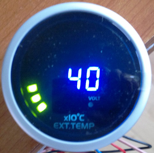 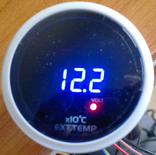 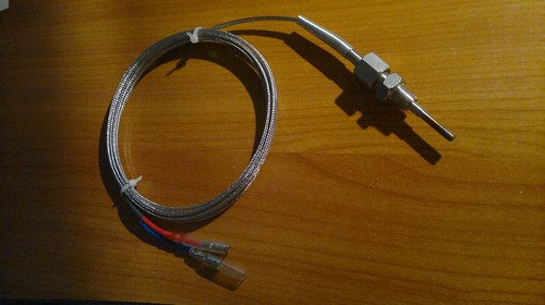 I ran out of Argon for the TIG-welder... I will get a new bottle so I can finish the FJK-2  Cheers Erik |
|
|
|
Post by Johansson on Oct 10, 2012 23:31:12 GMT -5
Nice temp meter!
|
|
|
|
Post by racket on Oct 11, 2012 3:16:58 GMT -5
Good solid thermocouple ..............nice stainless fittings :-)
|
|
nersut
Veteran Member
  
Joined: September 2012
Posts: 223
|
Post by nersut on Oct 12, 2012 21:26:39 GMT -5
Small Update I got a new bottle of Argon & I welded the new combustor housing & the flanges. Not too funny welding 1 mm stainless steel sheet...  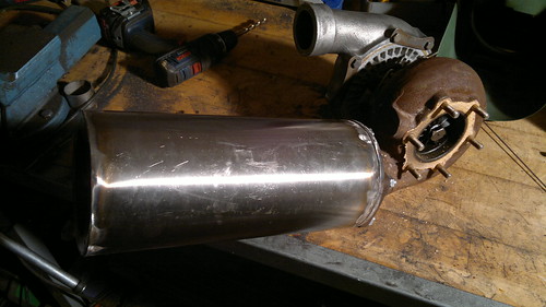 Combustor test fitted 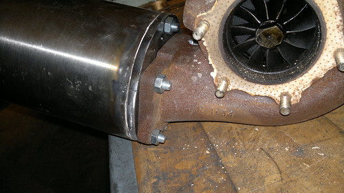 Turbo flange 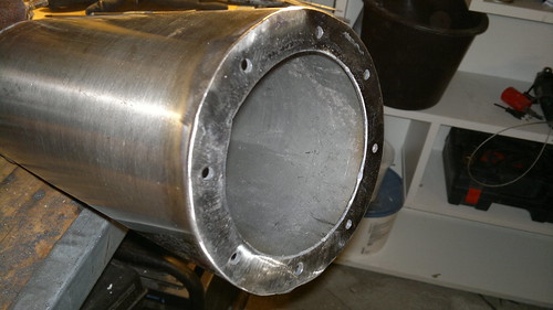 Top cap flange 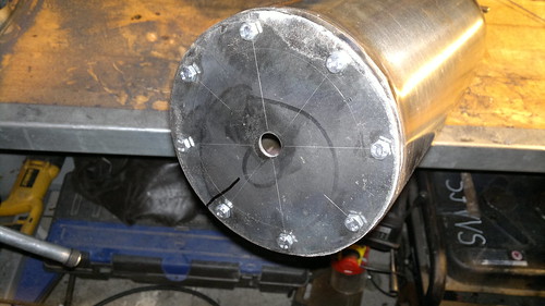 Top cap test fitted Tomorrow I will weld the flame tube together. I want to finish the FJK-2 as fast as possible but it is a little difficult with two jobs...  And I only have some very basic tools to play with. I build the FJK-1 & FJK-2 just using: - TIG welder
- Angle grinder
- Handheld drill
- And some handtools.
Not impossible it just takes more time. Yes the new EGT-meter looks cool! Cheers Erik |
|
|
|
Post by Johansson on Oct 13, 2012 0:48:57 GMT -5
Welding 1mm stainless is a royal pain in the ass, I must have layed a kilometer of 1mm weld during the pulsejet years but I never made one single centimeter that actually looked good.....
|
|