wolfdragon
Senior Member
  
Joined: April 2011
Posts: 287
|
Post by wolfdragon on Oct 13, 2012 15:37:54 GMT -5
heat control with stainless that thin is the key, also a good sharp tungsten
even then, functional and pretty are of exponential difference in difficulty...
I prefer ~1mm diameter ceria (orange color tip here in the USA) tungstens for that particular job
|
|
nersut
Veteran Member
  
Joined: September 2012
Posts: 223
|
Post by nersut on Oct 14, 2012 21:04:30 GMT -5
Update Today I was busy building the FJK-2. I reused the frame/oil system/fuel system/control panel from the FJK-1. The FJK-1 was basically "upgraded" to FJK-2 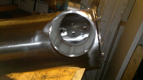 3 inch air inlet 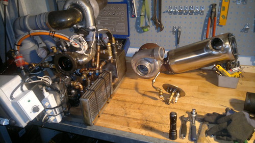 Before the upgrade 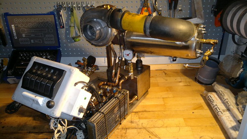 Almost ready for test run 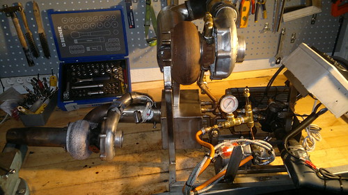 Size compare I tested the oil system, no leak! The new FJK-2 is almost ready for test run Still to do: - Connecting the fuel line to the nozzle
- Install the EGT-meter
- Install P2 pressure gauge
- Ignition source
I am not sure if I am going to reuse the spark igniter & try a glow plug...  Tomorrow I will install the last bits & test start it & hopefully it will run!  P.S. I used Megatronic WL 20 1.6 mm tungsten electrode with 1,8-2,2% La 2O 3 (blue tip) Cheers! Erik |
|
|
|
Post by Johansson on Oct 14, 2012 23:05:10 GMT -5
I´m looking forward to watch the video of the test run when I get back home from work on tuesday!  |
|
nersut
Veteran Member
  
Joined: September 2012
Posts: 223
|
Post by nersut on Oct 15, 2012 19:28:56 GMT -5
Update My new gas turbine build runs!  I fired up the FJK-2 today & it started at first attempt! Info: - 7.5 gph fuel nozzle
- 1.2 bar P2 pressure
- Only 450° celsius TOT temperature?
- 12 V automotive glow plug as igniter
Even I haven't installed/made a jet nozzle yet it produces a lot of noise & "wind"  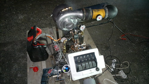 First run  The turbine wheel was black & oily but looks new after the test run 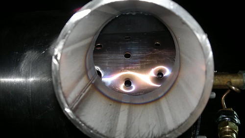 Primary zone discolored after test run Next step will be fabricating a jet nozzle & maybe a afterburner!  And install a breather tube for the oil tank Cheers! Erik |
|
|
|
Post by racket on Oct 16, 2012 3:21:40 GMT -5
Hi Erik
A couple of things I noticed that might be of interest .................your turbine wheel's exducer is severely cut back , you can see right through it , this might account for the "highish" TOT you experienced ,......... the lack of gas deflection caused by the exducer angle limits the turbine wheels ability to make power so we need higher temps to compensate , but its not a bad thing .
Another side effect of a "cut back" wheel is that it increases flow area , and if your scroll housing A/R is on the large side then the comp can be flowing towards the choke side of the map in less efficient regions , this also requires more horsepower so higher temps can be the result .....................be careful with your jet nozzle sizing , I wouldn't make it much smaller than the comp inducer diameter to start with , then if temps are within the limits at full power rpm ,a slight tightening of the nozzle can then be made to bring temps up to the limit .
Congrats on getting her up and running :-)
Cheers
John
|
|
|
|
Post by stoffe64 on Oct 16, 2012 12:41:12 GMT -5
congratulations are in order here, i really like your engine,looking forward for more updates regarding jet nozzle and afterburner
cheers/stephan
|
|
nersut
Veteran Member
  
Joined: September 2012
Posts: 223
|
Post by nersut on Oct 17, 2012 17:22:13 GMT -5
Hi John Thank you! I have some questions for you.  My TOT temp of 400-450° Celsius at max fuel pressure (with the current fuel nozzle) is still 200-250° lower than my max target of 650° Celsius TOT... Is my fuel nozzle too small? or will the temp rise up with about 200° Celsius if I just installed a jet nozzle?  P.S. the Turbine housing A/R is 1.34 & the Compressor housing is 0.74 I was hoping for more P2 pressure because the max P2 pressure was 1.1-1.2 bar. Minor setback. Yesterday I tried to start the FJK-2 up but no ignition... And flooded the engine.  The old glow plug was dead. I think it got too hot when I tested the engine. The top cap were the fuel nozzle & glow plug was installed was glowing red. Maybe I should install the spark igniter back or modify the flame tube/top cap to lower the temps at the top. Cheers Erik |
|
nersut
Veteran Member
  
Joined: September 2012
Posts: 223
|
Post by nersut on Oct 17, 2012 17:30:52 GMT -5
Hi Stephan Thank you! I am also looking forward to the afterburner part too!  But I have to deal with some minor setbacks & more testing before I make an afterburner. I will update the progress frequently. Cheers Erik |
|
|
|
Post by racket on Oct 18, 2012 2:39:13 GMT -5
Hi Eric
A correctly sized jet nozzle will bring your temperature up to the desired level .
To get more P2, you'll need more fuel .......................if you do the maths for your current setup you'll notice that the mass flow must be pretty high if you have such a low TOT , this could indicate the over sized turb stage is allowing the comp to flow in the choke region .
The red hot end cap on the combustor can indicate that there is recirculation of flames , you need more air at the very top of your flametube so that it creates a cooling air blanket against the end cap .
You appear to have a limited number of end cap fasteners holding a rather thin plate against the combustor , with full potential P2 pressure on the end cap it will most likely bend and leak with the current number of fasteners , I'd suggest adding a couple more fasteners between each of the current ones so that fasteners are no more than an ~ 1inch apart
Just a few minor teething problems we've all experienced :-)
Cheers
John
|
|
tegwin
Member
 
Joined: February 2012
Posts: 19
|
Post by tegwin on Oct 18, 2012 8:14:55 GMT -5
Hi Erik. That is a really nice looking engine.
Do you have a link to any larger photos? I would be interested to get a better idea of how you have it all plumbed together etc.
What are you using for oil and fuel pumps?
Thanks.
|
|
nersut
Veteran Member
  
Joined: September 2012
Posts: 223
|
Post by nersut on Oct 18, 2012 11:27:27 GMT -5
Hi John Thank you for your answers.  I think I will make some 4-6 x 10 mm holes at the top of the flame holder for better cooling. Or should I go with many small holes? And I am going to install 2 fuel nozzles instead. The first one for start up/pilot flame with a small 0.5 gph nozzle. The second for main fuel nozzle 7.5 or 9.5 gph. This is because the current setup with one big fuel for start up tends to over fuel/flood the engine at start up with a meter long flame at the turbine outlet.  Looks cool, but not very health for the turbine wheel (a have learned) ;D I will install 8 more bolts at the end cap later. Cheers Erik |
|
nersut
Veteran Member
  
Joined: September 2012
Posts: 223
|
Post by nersut on Oct 18, 2012 11:38:11 GMT -5
|
|
nersut
Veteran Member
  
Joined: September 2012
Posts: 223
|
Post by nersut on Oct 18, 2012 23:54:40 GMT -5
Update Hi I purchased a Allison Rolls Royce 250 3rd turbine wheel on eBay auction for only 78 USD!  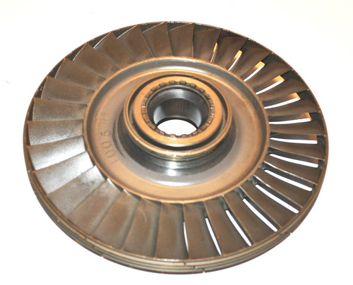 I will try to make a power turbine stage later on. Cheers Erik |
|
|
|
Post by racket on Oct 19, 2012 0:32:07 GMT -5
Hi Eric
Heh heh , you got it , its good for >100 hp on a large DIY engine , its the size I used on my first turbine bike .
With your endcap cooling , try getting a small centre punch and fit it into the top row of flametube holes and "bend" the hole "up" so that it directs the air jet towards the endcap , if this still isn't enough cooling you'll need to add some extra holes at the very top of the flametube wall ,.................as it appears your engine is flowing a bit more than ideal air flow due to the oversized turb stage , some extra air into the primary zone won't hurt . ..................I'd be adding only a few holes but of ~10mm diameter so that they force air towards the fuel injector rather than the axial wall cooling effect if a lot of small holes were used .
Cheers
John
|
|
nersut
Veteran Member
  
Joined: September 2012
Posts: 223
|
Post by nersut on Oct 20, 2012 3:32:25 GMT -5
Update I took the combustor apart after the first run to inspect the flame holder. 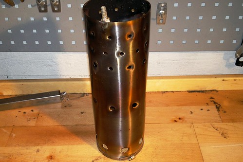 The flame holder is discolored evenly with no signs of hot/cold spots.  I bored the first row on the primary zone up to 10 mm & "bended" the holes upward to the end cap to cool the end cap & fuel nozzle. I also installed a spark plug just before the secondary zone. 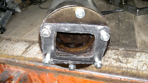 Here is the turbo flange/gasket & the slip joint is visible. Today I will test run it to see if the larger holes helps to cool the top & to test the spark igniter. Cheers Erik |
|