stevep
Veteran Member
  
Joined: November 2012
Posts: 120
|
Post by stevep on Dec 20, 2012 21:36:20 GMT -5
Welcome to my liquid rocket motor build thread. The goal is to build a 50lbf thrust motor that can be throttled, roughly 2" in diameter, and that can be flown to moderate altitudes, say, less than 10,000 ft. Current plan is to use nitrous oxide as the oxidizer and diesel as the fuel.
I have a decent background in designing/building/flying solid fuel motors and rockets which I expect to come in handy.
I've poked at the project a bit here and there over the years, mostly reading, but thanks to Carl and Anders, I've gotten motivated to actually put some real time into it. No promises that the momentum will continue or that updates will be regular--I've got a bunch of other irons in the fire and this one is lowest on the totem pole.
However, I wanted to report some of my results/thinking for the benefit of Carl and Anders (and anyone else who drops by) and didn't want to clutter their threads with info about my project, so I'm "going public" with what I'm up to. Besides, why should they have all the fun :-)
Comments/questions are most welcome.
|
|
stevep
Veteran Member
  
Joined: November 2012
Posts: 120
|
Post by stevep on Dec 20, 2012 21:38:26 GMT -5
I'm the sort who reads research papers, so I've spent a lot of time at ntrs.nasa.gov over the years, as well as jpl and any place else that hosts research papers. In addition, I've scoured the Unreasonable Rocket, Rocket Moonlighting, Robert W., Choked Flow, Scott Fintel, and Armadillo blogs and taken copious notes on what went well and what didn't. Based on this reading, combined with my development of solid motors, I've come to some conclusions about the best way forward for me, given my goals and resources.
As I said above, this project is pretty much my lowest priority given what else I've got going on. And that goes for both time and money. This will be done on a shoestring.
Given that the motor has to fly, cooling becomes a major factor in choosing fuels/oxidizers. The choices are regenerative, film, and dump cooling. Dump is wasteful and you still need the cooling channels. Film cooling is tricky since the entire chamber wall has to be covered with no gaps. Regenerative is usually thought to be difficult because the channels are hard to fabricate, but after spending lots of hours studying the problem, I think I can drill the passages longitudinally in the wall of the chamber. More on this in a future post, but the bottom line is that regenerative is what I'll be pursuing.
Fuel/Oxidizer choice: It seems clear to me that there are three potential choices after the really poisonous oxidizers are ruled out: hydrogen peroxide, LOX, and nitrous oxide. Hydrogen peroxide: After reading about the amount of time Paul Breed, the Armadillo folks, and others have put in trying to a) obtain it, and b) catalyzing it reliably, I have concluded that it's a fool's errand. Unless you have a nailed down, guaranteed supply of the grade you need (in quantities you can afford/are willing to store), and someone gives you (probably under NDA) a known, working cat pack recipe, you are just not going to get it to work effectively enough to be useful. If it were easy/straightforward, those guys (who are pretty darned smart and spent a lot of time/money on the problem) would have gotten something working. More recently, the guy at Choked Flow has been trying and getting somewhere, although not without a lot of effort and it's not clear that what he's got so far is very effective. So hydrogen peroxide is out (for me).
Lox is, well, lox. It's cryogenic which creates logistical problems, especially if you have to cart it a long ways to do your testing (as I will), and makes loading and valving much more difficult. It also creates a lot of requirements for cooling the chamber (it burns pretty hot) and restricts the materials one might use for tanks, piping, the injector, etc. It *can* be done, as Robert W. and others have nicely demonstrated. But it cannot be denied that it *is* more trouble than nitrous. It also requires a pressurization system, typically helium.
Nitrous (for me) has the advantage that I can go to a race shop and just buy some. Yeah, it's expensive compared to lox, but storage is easy. Yeah, its density-ISP is lousy compared with lox, but I'm not going to orbit, so it just doesn't matter. Yeah, the flight tanks have to withstand higher pressures than with lox, but at my size, minimum gage issues rule, not pressure issues. It needs to be treated with care, but there's a solid record of it being used safely in hobby rocketry and in performance cars and the hardware is much less expensive and more readily available than lox hardware. It is also self-pressurizing which offers advantages when building *small* rockets--if I were attempting something orbital, I'd be looking at Lox with a separate pressurization system.
Fuel comes down to one of the alcohols (ethanol, methanol) or a hydrocarbon like kerosene, jet fuel, or diesel. An alcohol has the advantage of being easy to clean up (it evaporates readily), but has a low boiling point compared with the hydrocarbons which makes cooling harder. There are more sources of information on regenerative cooling with hydrocarbons than with alcohol, and my inclination is to build on the work of others wherever possible, so while I may eventually switch to alcohol (or at least try it), my first attempts will be with a hydrocarbon, probably diesel because it's easier for me to obtain than kerosene. Also, its composition may well be more controlled and better characterized (because of anti-pollution regulations) than kerosene.
So there you have it: in contrast to Anders and Carl, I have to spend a lot more time/effort on cooling and weight and I will have valve issues they don't have (cheap, light, small, actuated valves are remarkably hard to come by). And, assuming it gets into the air, it has to come down under control--but I've solved recovery problems with solid rockets, so I consider that part "done".
|
|
stevep
Veteran Member
  
Joined: November 2012
Posts: 120
|
Post by stevep on Dec 20, 2012 22:23:45 GMT -5
Motor work to date: many months ago I made a small coaxial injector, flowed some water through it at about 50 psi (3.5 bar), and wasn't impressed. The center post was held in place with an o-ring and screws and didn't stay centered very well so the water flowed through the annulus in an irregular way which I have since learned is partially due to water's high surface tension. 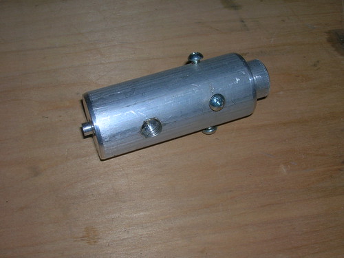 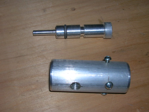 But as a result, I read up on impinging injectors since they seemed to be what most amateurs were using. The knock against them is that they require lots of small, precisely drilled holes. I'm used to drilling small holes in printed circuit boards, so as a test I drilled a few 0.021" (.5mm) holes in aluminum plate just to see if I could do it without breaking too many bits. It's definitely doable, even on an angle, but it is clearly more effort than drilling for a coax injector. And if you want really high combustion efficiency (>95%) when using liquid/gas components, you have to drill them at a *compound* angle which requires 2 different setups thereby making the process much more difficult, especially when the only tools available are a drill press and a lathe. Another complication is that most of the research on impinging injectors is liquid-on-liquid (whether unlike or like). Nitrous is a funny substance--as far as I can tell it will come out of the injector as a 2-phase flow (part gas, part liquid) and it just isn't clear how to size/arrange the holes for an impinging injector based on that. But nitrous behavior is far from clear. Scott Fintel has a photo showing a 0.125" diameter nitrous stream coming out as a liquid. Rocket Moonlighting shows an expanding plume of gas emanating from an orifice of undisclosed size, but probably much smaller than 0.125". Documents from Aspire Aerospace indicate that with small orifices (and they recommend sizes smaller than 1.5 mm), liquid nitrous will turn gaseous within the orifice (due to the pressure drop) although there may also be 2-phase (liquid and gas) flow. I suspect a lot of its behavior is dependent on orifice size and I'm just going to have to do some cold-flow experiments to see what the heck it does given the orifice size(s) I'd likely be using. The other issue I faced was how to mill the channels in the back side of the injector plate(s) for the oxidizer and fuel. I don't own a mill and wasn't going to buy one (and find the space for it) just for this project so I learned how to do some simple milling on my lathe. It's slow, the work envelope is small (about 4" (100mm) by 4" on my 9x30" lathe), but, so far, it does all that I need for a small motor. I've cut channels in both aluminum and steel (but not stainless). Recently I stumbled on Carl's blog and immediately recognized the worth of his strategy of using a bolt as the center post for a coaxial injector. This swung things back in favor of a coaxial injector. So, Carl, I stole your idea, and made a test injector (somewhat smaller than yours) to play with. Now I just needed a way to pressurize the fuel and a source of high pressure gas for inert, cold flow testing, a small test stand, etc. That's what I've been working on over the past few weeks. Also, I knew that I did not want to do even cold flow testing with nitrous without some sort of remote control over the valves and since I'd need actuated valves for the hot firing tests (as well as flight) I spent considerable time coming up with something usable in this department. I have over fifty items of "lessons learned" about valves from Unreasonable Rocket and Armadillo. They had cryogenics to worry about and I don't, required precision control over the valve which I don't, but my space and weight issues are tougher than theirs, so there are still a lot of issues to deal with. At this point I have a prototype that seems viable, assuming what I have is nitrous-compatible. I'll deal with the details in a future post. Finally, after doing a lot of work with solid motors, and taking to heart the experiences of others, my mindset going in to all this is *it will not work first time*. Sure, I may get flames, but will it create the necessary thrust? Will it cool properly? Probably not. Actually, almost certainly not. And it probably won't be right the second and third times, either. There is going to be a lot of experimentation and I have to set things up to make that efficient. I will be hampered by this in that I have to drive 3 hours each way to a suitable hot-fire test site. That puts a premium on cold flow testing, most of which I can do in my back yard. If you believe that you are going to fail often, then you want to fail fast (and cheaply). But you also want to fail in a way that provides guidance for the next step, otherwise you'll just be shooting in the dark. The problem with rocket motors is that it often isn't obvious what's wrong. With liquids, for example, it could be chamber length (L*), drop size, or mixing that's off (assuming you haven't burned through). Somehow you have to disambiguate that situation. Knowing some theory helps, as does adequate instrumentation for gross things like chamber pressure, but that won't provide all the answers. You'll therefore see me thinking/discussing/trying some things to do with drop size and mixing efficiency. Also, my injector and nozzle are designed to be used with relatively simple-to-make chambers so L* can be varied without rebuilding everything from scratch. So that's it so far: actuated valves, milling, test injector, pressurizable fuel tank, a test stand, and lots of thinking about how I'll figure out what's wrong when it doesn't go right. |
|
stevep
Veteran Member
  
Joined: November 2012
Posts: 120
|
Post by stevep on Dec 20, 2012 22:26:00 GMT -5
Drop size: it doesn't take much reading in the literature of liquid rocket motors to discover that drop size and mixing are hugely important to getting efficient combustion. The history of liquid rocketry combustion (indeed most combustion in general) is about those two issues. To start with, let's take drop size.
I didn't have any experience with this, and reading about drops being 100 microns in diameter didn't really register in a physical way, so I decided to get some cheap easy experience with drop sizes and their production with something readily available and utterly simple: a can of spray paint. I ran it quickly across a sheet of white paper so that what appeared on the paper was individual drops, not a solid coat of paint. Then I got out the calipers and started measuring.
Immediately I could see a large variation in drop size: a good number were 0.025" (0.6mm) in diameter, many were about half that, and many were too small to accurately measure. Also, as you'd expect, there were a heck of a lot of drops--way to many to count by hand (to get a drop-size distribution). I also noticed that when I was spraying, there was a mist that hung in the air for a second or two after most of the drops had hit the paper, and I assumed those were smaller than what I saw on the paper.
Most of the papers I'd read indicated that I wanted to be shooting for drops less than 100 microns in diameter, so the spray paint experiment gave me a good feel for what I was looking at doing. 100 microns (0.1mm) is about 0.004" so you can see we're dealing with pretty small objects. And it's clear that measuring them with dial calipers isn't going to work :-) That started me thinking about low-tech ways of assessing drop size. More (much more) on this later....
|
|
stevep
Veteran Member
  
Joined: November 2012
Posts: 120
|
Post by stevep on Dec 20, 2012 22:40:09 GMT -5
Here's the one I made after reading Carl's blog. 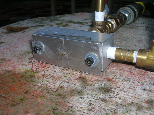 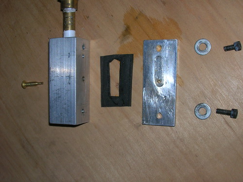 The nitrous will come through the opening in the center post, the fuel (liquid) through the annulus. Vital statistics: nitrous orifice diameter = .062" (1.6 mm), total annulus area 0.003in**2 (1.6mm**2), annulus gap = about .005" (0.127mm), equivalent orifice diameter = 0.063" (1.6mm). Machining the post wasn't that hard although it took me a few tries to get it exact, and the hole is a bit off center. It's a bit hard (ok, impossible) to get the post centered *exactly* such that the annulus gap is exactly .005 all the way around, but I can come close. It's easy to *see* that it's not centered, it's just a bit hard to adjust it (having a resilient gasket doesn't help). 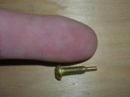 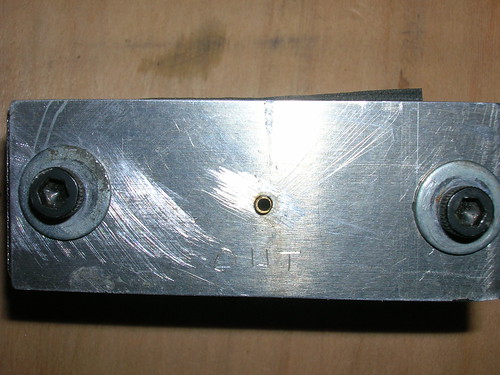 The plate is designed to be interchangeable without having to machine a new block each time I want to make a change. I can even (I think) make some impinging orifices if I want to go that direction. The gasket is just some 0.0625" (1.6mm) EPDM I happened to have lying around--I just cut the opening with an Exacto knife (good enough for a first test or two). Here are some photos of it in operation: 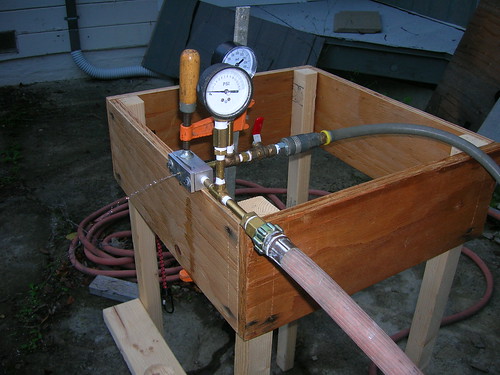 The photo above is just water flowing at almost no pressure. 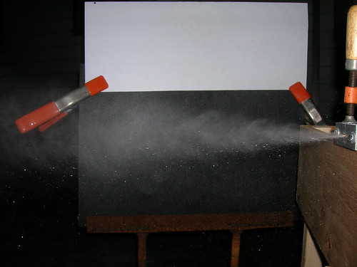 This is the same water pressure as before, but with about 40 psi of air going through the center post. So how well does it work? I don't know. And there's the rub. I can obviously make a spray and it *looks* like the drops are small, but are they small enough? And how do they vary with pressure? Not to mention what will it look like with nitrous rather than air? |
|
|
|
Post by racket on Dec 20, 2012 23:08:24 GMT -5
Hi Steve
Heres a trick you might find helpful with drilling small holes .................when I was trying to silver solder 23G syringe needles (O.65mm OD) into a 3/16" OD stainless steel tube for my turbine engines fuel manifold I kept on breaking drill bits , I found by fitting a small centre punch into my drill press and forcing it into the stainless tube wall it wouldn't quite break through the wall thickness if care was taken with the force applied to the drill press handle , the remaining wall thickness was then easily drilled using the Dremil and fine drill bit.
By having the centre punch in the chuck it was possible to accurately position the holes on the curved surface of the tubing at virtually any angle I wanted once a simple jig was made to position the tubing .
When I was a teenager (~50 years ago) I experimented a lot with home made gunpowder packed into steel water pipe ( of increasing diameters as time went by ) to make both muzzle loading guns as well as rockets , ...... to produce a fine wick hole in the muzzle loading barrels I used a hammer and a "Ramset" nail to "forge??" a fine hole through up to a quarter inch of steel.....necessity really is the mother of invention :-).
Cheers
John
|
|
|
|
Post by ernie wrenn on Dec 21, 2012 8:38:24 GMT -5
Using a ultra small center drill bit will keep the hole from walking. Use it to spot the hole, then switch over to your finished hole size. They will also let you drill at angles without wobble. We drill jetting down to .003 for use on our Nitrous Systems. WWW.COMPUCARNITROUS.COM For testing purposes use Co2 for the nitrous substitute. Same pressure and temps. ERNIE |
|
stevep
Veteran Member
  
Joined: November 2012
Posts: 120
|
Post by stevep on Dec 21, 2012 13:00:35 GMT -5
Hey guys, thanks for the drilling tips.
In this particular case I did use a small center drill (actually a spotting drill, but same idea). I don't believe the bit wandered but, rather, that the bolt was a mite off center in the jig I had it chucked in. The jig was just a scrap of solid round aluminum bar with a hole drilled through the center and tapped to fit the brass machine screw. The jig was chucked in the 3-jaw and then drilled. This was just proof-of-concept work, so I wasn't overly concerned with precision.
My next version will consist of a jig that is turned between centers to make sure it's uniformly round, then chucked in the 4-jaw and accurately aligned. The tapping will be done with a tap that has tighter than usual tolerances, assuming I can find machine screws with commensurately accurate threads. But all that's a ways down the road...
Enie: where the heck do you find a .003" drill bit? That must take a very delicate touch.
Good idea about the CO2--lots of home-brewers use it and there's lots of off-the-shelf fittings etc for it (as well as cheap tanks). And it should mimic the 2-phase flow of Nitrous well enough to get a decent handle on things.
--Steve
|
|
|
|
Post by turbochris on Dec 22, 2012 10:15:37 GMT -5
Ernie just uses his whiskers for .003 drill
|
|
stevep
Veteran Member
  
Joined: November 2012
Posts: 120
|
Post by stevep on Dec 22, 2012 15:19:51 GMT -5
Shortly after I made my first spray with the coax injector a few days ago, I started working on some ways to determine how fine the spray was. Months ago, in earlier trials of some hacked-together impinging injectors (air stream on water stream), I found that I could collect drops of the spray on a sheet of stiff plastic by "cutting" through the spray they way you would with a sword. A variety of drop sizes could be seen and different trials clearly showed that some methods made smaller drops than others. Just as with the spray paint test, I could measure the larger drops with calipers, but the smaller drops were too fine to measure accurately. Also, I didn't have any way of calibrating what I saw on the plastic with a known drop size--the usual problem is that the drop you capture (using whatever method) is altered by being captured and you need to calibrate what you see captured with what is actually flying through the air. But it was a low tech approach that seemed to have merit so I tried it out with the coaxial injector. So here are some observations using shop air (125 psi max (8.5 bar)) and water from the household supply (about 50 psi (3.5 bar)) Full water pressure (no air) would shoot a stream about 15' (5m). When combined with air, it appeared that atomization was occuring feet from the injector, rather than inches, so water pressure was reduced to that which created (without air flow) a jet of about 12" which turned out to be such low pressure that my 0-15psi (0-1 bar) gage registered "0". Varying the air pressure, I found that 20-40 psi (1.5-3.0 bar) seemed to result in the most fog-like spray; more pressure just seemed to move the atomization downstream many feet when where I want it is an inch or two from the injector. For the following photos I used the 20-40 psi air pressure. The photo below is of drops made by an ordinary hand-held household misting bottle (often used for window cleaners, etc.). I placed a very fine wire on the surface to get a sense of scale--the wire is 0.007" (.18 mm) in diameter, making it about 2x the size of the drops we want. In the photo you can see many very large drops, but also quite a few very small ones. Obviously we want to get rid of the big drops and, if possible, make the small drops even smaller. 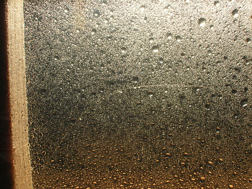 The next photo was taken about 12" from the injector. It appears that there are a great many small drops, but still some very large ones as well as some medium-sized ones (just slightly larger than the wire). This photo is good news on many fronts: first, there are a lot of drops about the same size as the wire, maybe somewhat smaller. Not as small as I'd like, but we also don't know how what we seen on the plastic compares with what's in the air. Second, it looks like capturing the drops on plastic and photographing that may be a pretty decent technique. Better lighting and some post-processing may do the trick. As a method, it is simple and quick--about the only fabrication involved was to set up a stand to hold the plastic in the right relation to the light to highlight the drops. 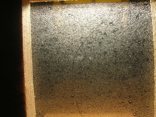 The third photo was taken at 100 psi (about 7 bar) and about 6" from the injector. The first thing you notice is that the drop density is much less than on the previous photo. This could be due to the speed at which I cut the spray with the plastic (it's just an uncalibrated swipe of the arm) or it could be that the higher air pressure is doing something to the spray. It does appear that many of the drops are somewhat smaller than the smallest drops in the previous photo, but it's really hard to be sure. 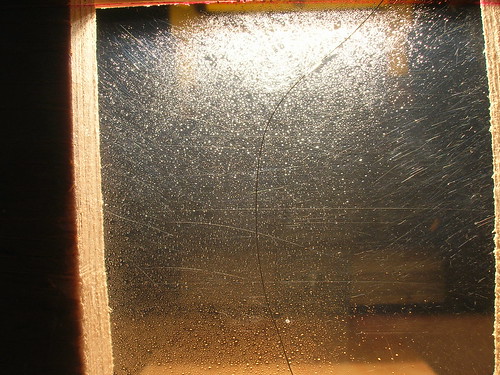 During all of this testing, I noticed that the spray pulsated. Slowly at low pressure and much faster at high pressure. The gage on the water line reported several psi (up from 0 psi) as soon as the air was turned on and distinctly registered the pulsation. Turning the air pressure up to 100 psi made the water pressure higher and the pulsation very rapid. It would appear that somehow the air is doing something to the air pressure right at the injector which is inhibiting the flow of water. This was repeatable, and did not occur in the absence of airflow, so it doesn't appear to be due to fluctuation in water supply pressure. Water was supplied via an ordinary rubber garden hose which had a fair amount of elasticity, which could be observed when turning the water on after it had been off for a few seconds--that is pressure would start out high then quickly subside to a roughly constant level. While pondering all of this, I have also been doing a ton of reading. I managed to wade through the Lasheras paper mentioned in Carl's blog and wrote a short snippet of code to do the basic calcs. Carl mentioned shadowgraphy so I found an online copy of a good reference book on the topic, "Schlieren and Shadowgraph Techniques" by G.S. Settles and a bunch of stuff on measuring drop sizes. It turns out lots of different industries care about drop sizes (agriculture for irrigation and pesticide sprays), meteorologists who care about fog and drop size in clouds, as well as the usual combustion folks (diesel sprays, turbine sprays (for cooling), etc.). Learned about some low-tech ways people of attempted to measure drop sizes in the past, and some high-tech (and expensive) ways they do it today. Also started reading about cheap high-speed photography of water drops--there are some amazing photos on the net. Basically the problem with photography is seeing through the mist, stopping the motion, having enough resolution to see the finest droplets, and some way of counting so that a distribution can be calculated or at least estimated. By capturing the drops on my plastic, I'm effectively eliminating the first two problems (while creating some others, of course). Suffice it to say that my little "point and shoot" camera is inadequate for directly photographing the spray, at least using methods I've devised so far. A new DSLR would do the trick but it's outside my budget for this project, so I'm looking at various cheap options: One, my P&S camera has a fast shutter speed (1/3000 sec), but there's no manual control over it. However, I'm thinking I may be able to fool it into using a fast shutter speed if I use enough light. I'll be trying this in the next few days. It has the resolution--I verified this by taking pictures of hairs (about .002"-.003" -- right in the range we want the drops to be). Two, if I had a DSLR with a "bulb" shutter setting, I could (in the dark) open the shutter, fire off a very fast strobe, and then close the shutter again. A fast strobe is fairly easy to make with the high-power LEDs now on the market (there are tons of directions for doing this on the web). Ebay shows a few cameras that I can probably afford that will work, I think. But I'd like to hear from Carl first about his ideas before I go spending money. Three, use some of the older, low-tech approaches such as gelatin "traps" for drops (one researcher even looked into using spider webs to capture the drops!). It turns out that really small drops (even of water) have an annoying habit of evaporating before they can be measured--this has caused researchers in the past to grossly mis-estimate the real drop size distribution as well as to conclude that drops were coalescing when they weren't. I will also continue to refine my present method of just capturing them on plastic and photographing that. Four, there may be indirect ways of knowing when we've got an injector that works. I have learned that atmospheric mist/fog is made up of droplets quite a bit smaller than 100 microns--in fact, down around 10-25 microns. So if the vast majority of our spray "hangs in the air" (like atmospheric fog) that would be "good enough" (probably better than good enough, actually). Also, there are photos on the web of sprays that are known to be made of droplets in the range we want; looking at these photos, you can see gross characteristics (like the edge of the spray being very indistinct as opposed to a "sharp" edge for a spray of large droplets). It may be that we can figure this out without actually measuring the drop size. Look again at the photo of my spray (the one with the injector spraying against the black background)--see how indistinct that top edge is? You can even see "waves". I'm pretty sure those are really small drops. I'll be doing some more with drop photography in the coming days. Obviously if anyone has any ideas, I'm all ears. I'm hoping not to turn this into a huge research project that will take years to complete, but I also don't want to be reduced to trial and error with a zillion hot fire tests. |
|
stevep
Veteran Member
  
Joined: November 2012
Posts: 120
|
Post by stevep on Dec 22, 2012 15:35:37 GMT -5
Better drop photos I wasn't at all happy with how hard it was to see the drops on the clear plastic. I tried a number of techniques for lighting the drops; lighting from below, which is what I did in the photos in the previous post, was the best, but the edges of the drops are just too indistinct, even with software edge sharpening (not that I'm an expert in that). This issue is mentioned in the book on schlieren photography and I've basically concluded (tentatively, of course), that while schlieren techniques are great for things that cannot be seen, like supersonic shock waves, for things that *can* be seen, direct photography may be a better option. And drops of water are hardly invisible--especially if you add some dye to the water. So that's what I did for the photo below--just added ordinary black fabric dye to the water in my hand-held spray bottle just for a proof-of-concept. This was sprayed onto a piece of white plastic and photographed with the same P&S camera used in the previous photos. The same wire is included for scale. This one was taken without flash: 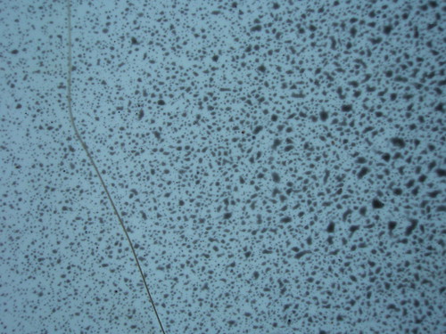 The focus isn't great (the wire is a bit fuzzy), but the drops show up fairly distinctly. The next one was taken with the flash: 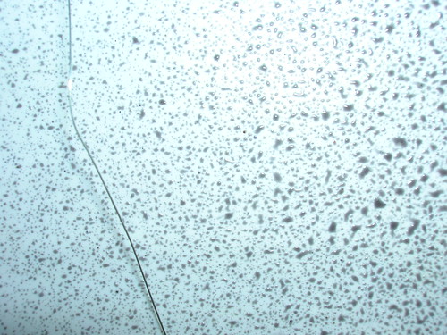 The wire is more distinct (a difference easier to see when the photo is greatly enlarged) and most of the drops are pretty visible--focus is noticeably better. But the problem with flash, of course, is glare. So I have some work to do with lighting, but the approach seems pretty good so far. Next step: load some dyed water into my fuel tank, figure out a way to get the water pressure just right, and see what happens. Only problem is that we're in the middle of severe rainstorms right now and since I do this stuff outside, it may be a few days before I have something. |
|
|
|
Post by britishrocket on Dec 31, 2012 15:26:55 GMT -5
Hello Steve,
Very interested to see your work on capturing and measuring drop sizes. I am also the type that reads research papers, and there cannot be that many of us about.
Your method of drop capture by slicing through the flow stream is ingenious and something I had not thought of. The only problem seems to be that as the drops hit the perspex sheet they flatten out, shatter and generally cease to be spherical.
In their experiments Falk and Burick used a technique called "hot wax freezing". The liquid simulant was a substance called "Shell Wax 270" which was heated and flowed through the centre post of the injector. The droplets produced then solidified as they cooled and were collected and measured against a graticule. These drop sizes were then corrected by a surface tension based relation for the actual propellants of interest. I have often wanted to try this method but I fear the outlay on equipment and set up would be quite extensive. As you say, I do not really want the drop size problem to become an all encompassing research project within itself, which it easily could, as you have no doubt realised.
Like you then I looked for an easy way to compare drop sizes of my sprays, and I also started looking at atmospheric fogs and mists, thinking to compare the images from my experiments with them. As you point out, it would be reasonable to assume that the drop sizes would be of a similar order if the mist/fog and spray look the same. After conversing with Dr Stickland of Glasgow University, I started to think that I should be aiming for a drop size that would be within a certain range, rather than needing to know the exact dimension. I can confirm that the sprays from my shear coaxial injector actually looked like jets of steam.
I am away from home working at the moment, but on my return I am aiming to set up the shear coaxial injector again and repeat some of my earlier experiments, primarily to get a feel for the problem again and to verify some of my earlier work. I will also try to get the shadowgraph set up worked out. I have some flash photography taken with a short shutter opening of some of my swirl coaxial experiments. I will try to get those posted here. they are quite interesting. The flash freezes the flow quite effectively and it is possible to see the conical sheet of swirling fluid ripping apart. This then leads to ligamentation and the formation of drops from these ligaments.
Happy New Year to you Steve,
Carl.
|
|
stevep
Veteran Member
  
Joined: November 2012
Posts: 120
|
Post by stevep on Dec 31, 2012 19:17:53 GMT -5
Hey Carl, Thanks for looking in and Happy New Year (probably already happened for you, depending on where in the world you are right now). I'm familiar with the use of wax for determining drop size--for a nanosecond I actually considered it, but better judgment took over. One of the great things about the meteorologists is that they fly planes through clouds collecting drops as they go. They therefore have the same concerns you raised, namely that the drop smashing into the surface of the capture plate will deform. They developed the gelatin-covered-slide technique and did some correlations with actual drops in a lab. The idea is to coat a microscope slide with a thin layer of gelatin (food grade works fine), let it dry, then arrange to have the drops impact the slide. The drops form the neatest little craters which dry and become permanent. There wasn't much in the way of guidance in the online literature so I sort of just re-invented the technique. I was hoping to just use their correlations between crater size and drop size, and may still do so, but the gelatin technique is a bit involved for on-ground use (they don't have a choice in airplanes because they can't do the actual measurements in flight--a permanent record was required so they could do the actual measurements back at the lab). The permanent record also avoids the issue of the finest drops evaporating before they can be measured (a problem even with quick on-ground measurements). There is also the possibility, which I tested, of trapping the actual drops in a thin layer of oil, but I discovered that this can get messy very quickly. Along the way, I found an easy way to get very fine droplets--much finer than I could get with a spray bottle: wet a toothbrush and run my thumb over the bristles. When the brush is nearly dry, the droplets that come off are *very* tiny. I'd guess well below 100 microns. So that gives me a "standard" to judge other methods against and is a dirt-simple way to create a spray for testing droplet capture/photography. I also got the photography of captured droplets under control: 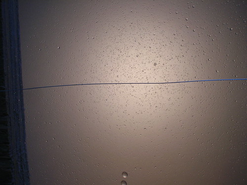 There's nothing special about these droplets, but the difference is using a piece of frosted glass between the lightbulb and the droplets. I also fashioned a simple holder for the wire so it is straighter and lies directly on the droplets (before I was just dropping the wire on there). I'm playing around with different bulbs and varying the placement of the frosted glass, but things look promising so far. Since I seem to be gravitating toward photographing captured droplets, I investigated the correlation between a drop in the air and one sitting on a surface. You'd be *amazed* at how much research is being done on that topic! It turns out that the surface tension of the liquid and the free energy of the surface (plus a bit of influence from gravity) pretty much determine how much the droplet spreads out on the surface. An index of this spreading is the "contact angle" formed by the edge of the droplet and the surface. Then you can do some fancy calcs and eventually figure out the relationship between the drop in the air and the drop on the surface, the drop on the surface having spread out a bit. It turns out that for my piece of plastic (acrylic) the drop spreads out to be about 50% bigger than it would be if it were perfectly spherical. The next issue is that with backlighting, the light diffuses around the droplet (and the wire), making them look a bit smaller than they really are. So I may need to take that into account at some point. Finally, I discovered that printing out the photo is vastly better than viewing it on the screen, because the printer has far better resolution--what is hard to make out in the on-screen photo is relatively easy to see in the print. There is still no way you'd want to measure/count the droplets by hand, but you can easily get a sense of whether you're looking at really fine droplets or fairly coarse ones. Not that I feel a need to measure/count each droplet, but I'd like something a little more definitive than my not-so-calibrated eyeballs. Having better photos of droplets prompted me to muck with the injector to get a better understanding of what was going on. First, I recessed the post. No visible change in droplet size. Second, I replaced the rubber garden hose water supply with copper tubing attached to the household plumbing. The pulsation didn't change. I played with this a bit, and discovered that it seems related to near-sonic flow of the air. More on this below. Three, I swapped air and water so that the air was coming through the annulus and the water through the post. This is the arrangement used by all the researchers so I thought maybe they knew something I didn't and that this arrangement was better than the one I'd been using (water thru annulus, air through post). No visible change in droplet size. Thinking I might be skimping on the air a bit, I made another plate with a bigger annular gap (I'll measure it if anyone cares). No visible change. So the net result is that I have a better idea of what isn't working :-) Pulsation: After playing with this, scratching my head, rereading some papers, and refreshing my understanding of choked flow, here's what I think: The spray is affected by the momentum of the gas compared with the momentum of the liquid. Gas is less dense, but is moving faster so it will have more momentum (good) than the liquid. You can increase the momentum of the gas by increasing the velocity and/or the density. Knowing that my air (at max 100 psi, 7 bar) isn't all that dense, I'd been cranking up the velocity & density by opening the valve wider. But that's when I'd get the pulsation. Below about 30 psi, I didn't detect the pulsation, above that I did, and the more I opened the valve, the more pulsation I got (higher frequency and more powerful pulses). Well it turns out that a 2:1 pressure ratio across an orifice will get you "choked flow"--which is when the gas is coming through the orifice at the speed of sound and will not come out any faster. Note that this isn't pressure *drop* but pressure *ratio*--the ratio of the pressure on the upstream side of the orifice vs. the pressure on the downstream side. Aha! 30 psi upstream vs. atmospheric downstream is just about 2:1, so as soon as I cranked it up to 30 psi, I was getting sonic flow. Well all sorts of things can happen when air tries to move at or near the speed of sound, so I am not at all surprised that weird things were happening. But, of course, that kills my density which I think is what is keeping my spray from being very fine. Now you might be wondering if all those researchers (whose papers we wade through) can make fine mists with air and water why can't I? Simple: they can use arbitrary flows of gas and water because they don't have oxidizer:fuel ratios to consider. The Lasheras paper used a truly miniscule amount of water with a gas flow of about Mach 0.3 to get their fine mist. I tried to duplicate that and almost couldn't get the water valve to crack open such a small amount--but when I got it close to their flow, I did in fact get a very fine spray. But I can't do that in my motor because I need way more fuel flowing. As soon as I bumped up the water flow to simulate the flow in my motor, the droplets just got big again (unless I cranked the air way up, but then I had the pulsation to contend with). I did capture some sprays (but didn't bother with photos) at high pressures and in between the pulses (which register as big "splats" on the plastic) there is a very fine mist--well below 100 microns. So my feeling at this point is this: I need more density in the gas. Argon would achieve this, but since I'm really not interested in a gaseous oxidizer, I think my next step is to start using liquid CO2. So after the New Year, I'll be busy getting a small cylinder to play with. Bottom line is that at this point I think I'm actually in fairly good shape: I have a way of roughly sizing the droplets, I know what really fine mists look like (pulsation notwithstanding), and I have a next step that is in line with my overall goal. Stay tuned! |
|
stevep
Veteran Member
  
Joined: November 2012
Posts: 120
|
Post by stevep on Jan 1, 2013 11:18:58 GMT -5
Carl, Your point that you/we should be looking at drop sizes within a given range is well-taken. As you probably know, the Sauter mean diameter is often used as a measure to characterize the drop sizes withiin a given spray. There's a nice, brief introduction to the topic here: www.thermopedia.com/content/1108/My own thinking is that once I get to the point where the vast majority of the droplets are below 100 microns, it's probably time to start hot-fire testing (assuming I'm satisfied with the mixing, a whole other topic [the gallery groans in unison :-)]). However, I will temper that with the effort it takes to get down to that size. If I find that, even after considerable effort, it still seems that the majority of the droplets are between 100 and 200 microns, say, I may decide to do some hot-fire testing just to get a data point. After all, it may turn out that I've reached the point of diminishing returns, that combustion is "good enough" with drop sizes between 100 and 200 microns, and that further effort to reduce the drop size wouldn't be worth it. It sounds like we have traversed the same terrain in thinking about this problem (wax droplets to fog analysis)--one of the great attractions (for me) in tackling projects like this is that one gets to learn about a range of subjects during the process. I look forward to studying more of your results as you find the time to post them. |
|
|
|
Post by Johansson on Jan 1, 2013 15:17:23 GMT -5
A very interesting build thread Steve! The level of ambition you and Carl aims at is waaaay over my own trial-and-error approach so I am following your progress in silence and awe.  Cheers! /Anders |
|