|
|
Post by Richard OConnell on Feb 22, 2013 20:43:26 GMT -5
And it seem s that you have survived the process of learning, which puts you ahead of the curve! GREAT SUCCESS!!!!!  |
|
stevep
Veteran Member
  
Joined: November 2012
Posts: 120
|
Post by stevep on Feb 25, 2013 8:24:11 GMT -5
While I was waiting for the parts to arrive from McMaster, I read through a paper I'd known about but not considered particularly relevant to rocketry: "Drop-size Distribution for Crosscurrent Breakup of Liquid Jets in Airstreams" by Ingebo and Foster, 1957. I've read a bunch of Ingebo's other papers and found them very useful, but rocket guys typically don't do cross-current injectors because (I guess) there just isn't room to fit all the necessary orifices in when half of them have to be at right angles to the others. Much easier to impinge at, say, 60 degrees. The context of the paper was (yes, I get the irony, here) jet engines which was another reason I hadn't bothered to read it. But having seen how difficult it was apparently going to be to get 60 degree impingement to work satisfactorily, I figured I ought to broaden my investigation some. So I read the paper, figured out how I might make an injector that fired the fuel at right angles to the nitrous, and went out to the shop to make a test piece. In the photo below, I'm firing water at 60 psi (4 bar) through a .021" (.5mm) injector at a stream of CO2 (coming from the right) at about 200 psi (14 bar) through a .029 orifice. I took this just to show how the CO2 stream deflects the water. 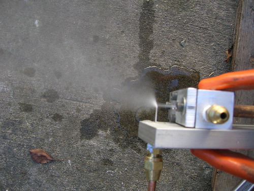 I cranked up the CO2 pressure to 400 psi (28 bar), and the water pressure to 100 psi (7 bar) hoping for great results. But when I captured the spray on the plastic, it appeared to be about the same as the impinging injector, though, so I was a bit disappointed. However, I thought to try it with the water at 40 psi or so, and the spray became much finer. OK, I've seen that result before: limit the water volume (or its velocity) and the drops get smaller. No news there, really. But what was very cool is that I could see how the water stream was bent by the flow of CO2--when the water flowed at 40 psi, it was bent before it penetrated very far into the stream of CO2--even when the CO2 was at a low pressure. At 100 psi, it penetrated almost completely through the 400 psi CO2 stream. And if I lowered the pressure of the CO2 stream to, say, 200 psi, the 100 psi water stream shot clear through the CO2 stream. This visual result is just not visible when the impingement angle is not 90 degrees--the water just sprays out in a big fan and you can't really see what's going on. Here, for the first time, I began to feel I was getting some insight into the mechanics of the spray. So the McMaster stuff arrives and I shove those two 0.010" (.25mm) orifices into an injector plate that impinged the two water streams at 60 degrees to each other with the two .0292" nitrous streams split between them. Not much difference from using the 0.021" water streams. I was hoping for a noticeable improvement so this was a bit disappointing. Then just for grins I tried out the two mister nozzles from McMaster--one was chosen for it's ability to approximate the fuel flow I want, the other was just the one that produced the finest mist. The one that does the right fuel flow produced gigantic drops--way bigger than anything I've produced on my own. Scratch that. Then I tried the super-fine mister and it produced mist so fine that when I captured it on the clear plastic it evaporated before I could photograph it! But, sadly, it would take a zillion of those to flow the necessary amount of fuel. Still, it was interesting to see that I'm in the right ballpark--looks like for a similar volume, my 60 degree impingement spray would be comparable to what theirs would provide (except theirs won't fit in the space I have available). So back to the 90 degree impingement effort. I slapped together another test piece, inserted a .010 orifice and got this: 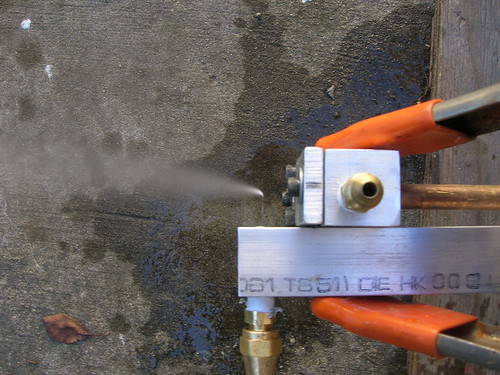 That's 100 psi water with about 100 psi CO2. You can see how even 100 psi water is nicely turned by a very low CO2 pressure. I then cranked up the CO2 pressure to 400 psi and got this: 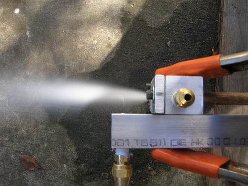 The water stream is completely obliterated by the stream of CO2! I captured the spray on the plastic and saw the finest mist I've ever produced--very much in the ballpark I've been hoping for (sorry it's so hard to see): 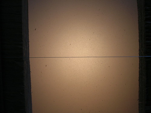 The amazing thing is that about half of the spray has evaporated already, that's how fine it was. This was taken about 3" from the impingement point and prior to this, I'd never gotten a spray that fine even 6-8" downstream. To get this at 3" was pretty amazing. Here's what I got with a .021 orifice for the water (100 psi, CO2 at 400 psi): 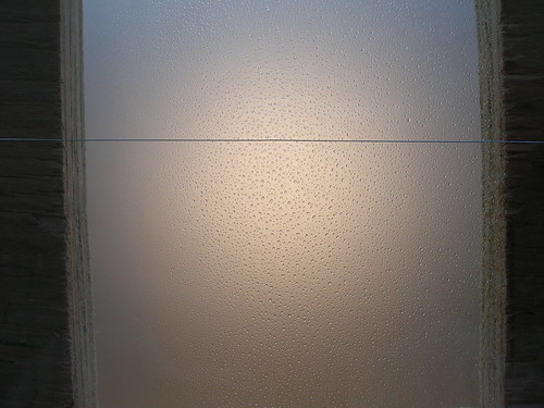 Clearly orifice size matters! But we're not done yet. How much water is flowing through that .010 orifice? Will I need a million of them to get the fuel flow I want? To answer this, I flowed water at 100 psi (no CO2) into a container and weighed it--turns out it was about 1/17th of what I need, meaning I'll need 17 or so .010 orifices, And, of course, I have to be able to drill holes that small. I did a bit of math and it looks like the ratio of CO2 orifice area to water orifice area is about 8.5:1 for the .0292 (CO2) : .010 (water) orifices. The ratio of .0292 (CO2) to .021 (water) is about 3.5:1. Clearly the 3.5:1 ratio results in huge drops and the 8.5:1 ratio results in small drops. Is there a ratio somewhere in between that would be easier to drill and flow enough more water that I could use a nice number of (say, 6) orifices? Might I be able to enlarge the CO2 orifice a bit which would allow me to use larger water orifices? Can I get by with fewer water orifices if I raise the pressure from 100 psi, to, say, 150 psi while retaining the small drops? Answering those questions is the task ahead. But first, I need smaller drill bits and yet another bottle of CO2. I've now used 40 lbs of the stuff! --Steve |
|
stevep
Veteran Member
  
Joined: November 2012
Posts: 120
|
Post by stevep on Feb 28, 2013 23:08:07 GMT -5
Just a quick update: I ordered some really tiny drills from DrillBitCity.com--they're resharpened carbide but have lots of flute area left and the price is very reasonable $2-3 each depending on size (smaller = more expensive, of course). Got 0.0110, 0.0120, 0.0130, 0.0145 and 0.0160.
First question I wanted to answer is just how small a hole can I reliably drill? Answer: .0130 for sure, 0.0120 if I try really really hard. Turns out my drill press has about .004" of runout 1" from the chuck so when I watch a .0120 bit under good magnification, it's wobbling around pretty wildly. I drilled some plates with .0145, .0130, and .0120 holes and fired up the test rig.
Things were going well until I realized that when I am capturing drops with the plastic, it really does matter how fast I move the plastic through the stream. Previously I'd just been slicing as fast as I could move my arm assuming that whatever variation there might be in the speed wouldn't be all that great and/or wouldn't matter all that much. But today I was taking pains to cut at the same distance from the injector each time and that was causing me to vary the speed enough to get vastly different results for the same orifice size--ugh! It also appears that even 1/4" (5mm) difference in where I cut the stream changes the results enough that I'm not totally sure what I'm seeing. So-o-o-o-o.....
I'm now cobbling together a mechanical contraption to move the plastic through the stream with a consistent (and measured) speed. I hope to have it working in a day or so since it's really low tech (surgical tubing provides the motive force) and I think I have all the parts on hand. Speed (really time) measurement is with a photocell hooked up to my oscilloscope! Should be interesting to see how much faster the rubber tubing is than my arm. I'll be sure to have photos of this thing...
--Steve
|
|
stevep
Veteran Member
  
Joined: November 2012
Posts: 120
|
Post by stevep on Mar 4, 2013 19:01:27 GMT -5
The goal for this past weekend was to build a machine that would cut the stream at a repeatable speed and at a repeatable distance from the injector. My idea was to use surgical tubing (like a slingshot) to propel a carrier on a track which ran at right angles to the spray stream. Here's the finished unit, seen from the position of the injector (which will fire the spray through the rectangular hole in the center. 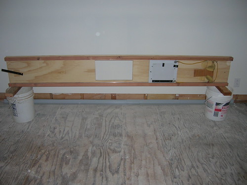 Towards the right end is the carrier (white) with the plastic attached via some (black) pins and a clasp. Farther to the right is a wad of foam rubber that acts as a shock absorber to stop the carrier. You can see wood pieces at the top and bottom: these contain aluminum channels that the carrier rides in. At the left end (black lever) is the catch/release handle--in operation the carrier is pulled back until a pin is caught by this handle. To release the carrier for its merry ride, one merely pulls up on the handle. Dimensions are 8' (2.5 m) by about 12" (30cm) high. It is wicked! You definitely wouldn't want your hand in the way--I timed it with the photocell timer I slapped together and after waxing the channels, it goes at 38 feet/second (11.6 meters/second). The fastest I could achieve by hand was 33 fps and if I relaxed at all it fell to 25 fps. The repeatability of the slicer is excellent: no discernable change over an hour of use, and no discernable change from one day to the next. Quite a bit better than Steve's arm. It can also be positioned at a set distance from the injector which eliminates that variable. Here's the unit set up for operation: 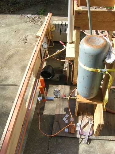 When there is just water flowing (no CO2), the water fires parallel with the slicer and into the ABS (black plastic) pipe to keep it from splattering where I don't want it. When I turn on the CO2, the stream goes through the rectangular hole. The wavy copper tubing conveys water to the injector (which comes from the needle valve and gauge) and the CO2 comes from the gray bottle and the brass/copper fittings (via valve and gauge). The water is stored in the vertical aluminum tube and is propelled by shop air at about 100 psi. For most of my tests, I've been using a pressure drop of 400 psi for the CO2. So, does it work? You bet! The captured spray patterns are very repeatable and follow the expected pattern: smaller water orifices (CO2 orifice constant) lead to smaller drops, larger CO2 orifices lead to smaller drops (water orifice constant). It is so consistent I was able to determine that one water orifice was partially clogged and I can also discern a difference between the orifices I drill and the 0.010" orifice from McMaster--for some reason the latter makes a different looking spray. I made up a spreadsheet of possibly useful combinations of water and CO2 orifices. There aren't a lot of combinations since the number of water orifices has to be an even multiple of the number of CO2 orifices (e.g., 3:1, 2:1, 4:1--you can't have 3.6:1). There are only a certain number of CO2 orifices: 6, 5, 4, and 3. More than 6 requires a hole too small to flow CO2 reliably (solid CO2 intermittently plugs it) and even 6 holes (.0292") is pushing it. Two orifices aren't symmetrical, and one is too forceful for the size chamber I plan to run (I think). Water orifices likewise are bounded: 0.010 is the absolute smallest I could conceive of using and 0.021" has already been shown to be too large for most CO2 orifices. That leaves approximate sizes of 0.012 (15 holes), 0.013 (12), 0.016 (8), 0.018 (6) and 0.020 (5), all of which work with one or more of the CO2 orifices to make a whole number ratio. For example I could use the 0.012 (15) against either 5 (3:1) or 3 (5:1) CO2 orifices and I could use the 0.013 (12) against 6 (2:1), 4 (3:1), or 3 (4:1) CO2 orifices. I don't need to test all possible combinations--if I start with the smallest water orifice and work up until the the drop sizes become larger than desired, I need not test any larger water orifices against that particular CO2 orifice size, since the larger water orifices will just produce even larger drops. What I've done so far: CO2 at 400 psi, Water at 100 psi, drops captured 3" from impingement point, impingement being 1" from CO2 orifice. CO2 orifice 0.0292" against water orifices 0.010", 0.012", and 0.013". Any bigger than 0.013 and the drops were huge--even 0.012 seemed to be producing a large number (the majority?) in the 200 micron range. Tentative conclusion: CO2 orifice .0292 is probably too small to produce drops such that the vast majority are less than 100 microns. Besides, it doesn't flow CO2 very smoothly--you can hear solid pellets going through and see the flow vary accordingly. CO2 orifice 0.036" against water orifices 0.010, 0.012, 0.013, 0.0145. It appeared that all sprays were finer than the corresponding 0.0292 sprays. Stopped with 0.0145 because the drops seemed to be exceeding 200 microns. Next up: CO2 orifice 0.042. After that, then I have to see what happens when I try to impinge more than one stream of water against a single CO2 stream. If it all falls apart (drops are too big with more than one water stream), it will be back to the drawing board. --Steve |
|
stevep
Veteran Member
  
Joined: November 2012
Posts: 120
|
Post by stevep on Mar 6, 2013 11:40:43 GMT -5
More spray testing I tested the 0.042 orifice and didn't get any useful results--no matter what water orifice I used, I just got "splatter". What I mean by this is that it was evident that the drops were hitting the plastic and coalescing, probably due to the slicing not being fast enough. I've seen this before, and actually was able to reproduce it at will when I was slicing by hand by simply slowing the slicing down. For some reason, it appears that the larger orifice is allowing the spray to travel faster, thereby allowing the drops to pile up on each other as they hit the plastic. I'd been afraid of this when I built the slicer and had considered ways of speeding it up if it became necessary. One obvious way is to make the carrier/plastic much lighter. I did a few test runs with just the carrier (no plastic) which cut about 1/3 off the total weight, but it didn't travel much faster. That tells me that the limit is due to friction, not mass, which I'm thinking is due to the carrier rattling around in the channels and the tubing not exerting a uniform force on the carrier, causing the ends "dig in". The way to get around this is with ball-bearing wheels, but that would mean different track and futzing with some other things--doable, but maybe not necessary..... Staring at my spreadsheet, it is fairly clear that there is a "sweet spot" of only a couple of combinations of oxidizer and fuel orifices. Oxidizer orifices are 0.0292 (6 holes, but the flow is iffy), 0.032 (5), 0.036 (4), and maybe 0.042 (3) but it isn't testable. The fuel sizes seem to be 0.010, 0.0120, 0.0130, and 0.0145. I've deemed the 0.010 as too small to be practical, the 0.020 is tough to drill on my equipment, and the 0.0145 seems to give drops that are probably too big. That leaves me (for now) with the 0.0130 (.3mm) fuel orifice as usable with the 0.032 (.8mm) and 0.036 (.9mm) oxidizer orifices (although the 0.0145 might have been OK with the 0.042 if the test results had been usable). Since the next question is what happens if I try a full injector with multiple fuel jets impinging on multiple oxidizer jets, it seems more productive at this stage to try to answer that question than to spend time improving the slicer in hopes that I'll discover that the 0.042 orifice produces a significantly better spray. The issue with the injector is that the fuel has to turn a right angle as it comes from the cooling channels in the chamber walls: 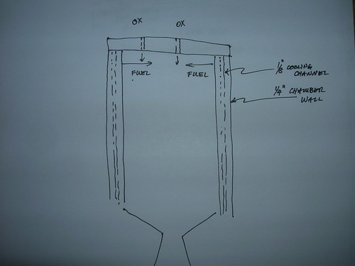 Making this happen would be dirt simple if I could drill right angle holes from the inside of the chamber, but with an I.D. of just 1.5" (38mm), that isn't going to happen--there's just no right angle attachment I can find that will fit, let alone allow me to reliably drill 0.0130 holes. I could drill through from the outside of the chamber, but then I'd need to plug the hole (without plugging the cooling channel), something I'm not particularly eager to do having attempted to braze aluminum in the past. Also, cross drilling through the cooling channel (really just a very long 1/8" hole in the chamber wall) would be problematic--I'd need a nice flat spot and starting dimple inside the cooling channel, which means starting with a much larger hole on the outside of the wall, then finishing with the 0.0130 drill which I couldn't see much of once it's inside the hole. All in all, it seems easier to make a ring that fits inside the chamber and which I *can* drill from the outside: 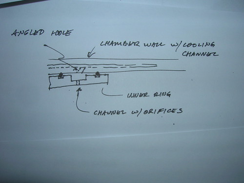 The idea is that the fuel will flow in the big channel in the ring, then into the chamber through the small holes. The fuel will be kept from leaking by two o-rings. The fuel will get from the cooling channels to the ring-channel via large holes drilled at an angle from the end of chamber: 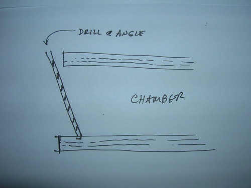 This works because a larger drill is long enough to reach, whereas the 0.0130" drill isn't (and, also, it doesn't matter if the hole leading to the ring's channel is at an angle, whereas it might if the 0.0130 holes aren't perpendicular to oxidizer stream). So that's what I'm up to. Already spent one long-ish session in the shop making one ring (fairly fast, I do this sort of thing a lot for my solid-fuel motors) and a mockup of the head-end of the chamber. The head end piece will have provision for interchangeable orifice plates so I can try different sizes/spacings of the oxidizer orifices. The rings are easy enough to make that I can make more of them if I want to try different orifice spacings. --Steve |
|
stevep
Veteran Member
  
Joined: November 2012
Posts: 120
|
Post by stevep on Mar 14, 2013 7:54:59 GMT -5
I completed the mock-up of the full injector a few days ago. It took an hour to drill the 12 radial 0.013 holes, but I didn't break a single bit, so I'm pleased with that. The procedure was a bit tedious, though: insert a "dummy" bit (broken off 0.020) as a fine pointer, line up the spot to be drilled, clamp the ring in place, swap dummy bit for 1/4" end mill, mill a flat spot, swap end mill for center drill, drill the starting hole, swap the center drill for the 0.013 drill, add a drop of very light machine oil, drill the hole by "pecking", remove the 0.013 drill, repeat. There was also some swapping of eyeglasses for magnifiying visor and back so I could see what I was doing at the various stages. I had drilled many of my previous holes dry, because I found that the colored oil I was using obscured the tip of the drill, but drilling dry caused the swarf to tenaciously cling to the bit so I hunted around for some lighter (and clearer) oil, finally settling on the oil I use for my sewing machine. Worked like a charm. Here's a shot of the assembled unit. You can see the plate (4 holes) through which the nitrous/CO2 flows and the removable ring (press fit) containing the fuel/water orifices fed by the brass fitting in the upper left corner. The ring is 2" (about 50 mm) in diameter, the size the motor will ultimately be:  Here it is disassembled. The ring (actually more of a cylinder in this version) has a channel that the water/fuel flows through to get to the tiny radial holes (just barely visible). The black gasket seals the plate, the o-rings seal the ring: 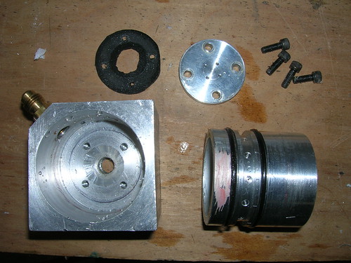 Here it is in action: 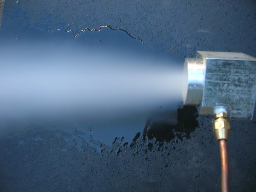 Hard to believe all that is going to burn up as it flows just a few inches through the combustion chamber! Unfortunately, the flow overhwelmed the measurement apparatus and all I got was "splatter" -- this was somewhat expected given earlier results with full-flow injectors, but still disappointing. I wasn't even able to get a good idea of the spray by slicing several *feet* (about one meter) from the injector. I therefore made a different plate (one hole, not four) and sealed off (with tape) all but one of the radial holes. Got a nice fine spray. Unsealed a second hole, opposite of the first, and again got a nice fine spray. Unsealed two more holes so that I had four, 90 degrees apart, and ran into some problems. First, I now have to be careful to start the CO2 before I start the water because otherwise the water will collect in the bottom of the "chamber" and skew the results (the flowing CO2 will eventually clear it all out which is fairly interesting in itself, but I have no idea what it's doing to the drops). Second, recirculation near the plate causes the water to freeze up around the CO2 orifice. This doesn't happen with the test articles I've been using because with them there isn't an enclosure around the orifices like there is now, so recirculation wasn't happening. In effect, what I have now is like a very short combustion chamber with no nozzle. Looks like I'm going to have to start testing "nozzle down" so to speak which makes data gathering a little more difficult. Before I can do that, I have to modify my test stand to hold the CO2 bottle higher off the ground. Also, while the injector is *probably* working pretty well, I don't really *know* that and I'd much prefer to have more definitive data one way or the other. Clearly my "sling shot" slicer isn't up to the task--even at 38 feet per second. I'm assuming (and therefore might be wrong) that sending the plastic through the stream at a much higher speed will solve the "splatter" problem. I really won't know until I try it, but I'm thinking that just doubling the speed probably won't be enough. I doubt I can get much more than that from the surgical tubing, so it's time to come up with a new way of slicing the stream. The good news is that I have an idea about how to do that. The bad news is that it's a bit scary--the easy part is to get the plastic and its carrier moving at a high speed; the hard part is keeping it under control and stopping it safely. --Steve |
|
stevep
Veteran Member
  
Joined: November 2012
Posts: 120
|
Post by stevep on May 4, 2013 8:50:39 GMT -5
I finally have some news to report--it's been a while because making a faster slicer turned out to be fairly involved. In my previous post I indicated that I had an idea for achieving higher speeds and that the hard part was going to be to stop the thing once it started. That turned out to be precisely the problem. The idea was to use compressed air to propel a piston which carried the plastic; the propulsive device is simply a "spud gun" ("spud" being American slang for "potato"), plans for which abound on the 'net. They're easy to make--just some pressure rated PVC tubing typically used for home plumbing or irrigation along with a modified sprinkler valve. Muzzle velocities vary, but can be as high has 100 fps (30m/sec), about 3x what my surgical tubing slicer was getting. As you can see from the photo, I simply mounted it to the same wooden "rail" I had been using for the surgical tube version. 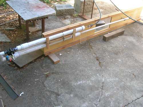 Instead of propelling a piece of potato or other round projectile, I made a piston which I attached to a long piece of 3/4" diameter pvc tubing. This slides through a guide at the muzzle and another guide several feet "down range". The plastic is attached in between the two guides and a padded stop is placed a couple of feet past the down range stop. The details are fairly uninteresting beyond the fact that the speed generated by the compressed air is astonishing. There is *no way* you can see the thing move: one moment it is sitting in the "ready" position, the next instant it has flown the distance! The problem was stopping the thing. For weeks I shattered plastic in all sorts of ways and I soon tired of rebuilding the piston, reattaching the plastic, and attempting to devise a new stop. I finally ended up with a heavy spring on the end of the piston which slammed into several layers of some sort of heavy foam which was attached to an 80 lb (36 kg) concrete block. The sudden stop would cause the plastic to break away from the piston (despite being held on by several screws) and often I'd shatter the piston, too. Usually the plastic would be in shards all over the place--useless for seeing any drops. The obvious thought was to beef the whole thing up, maybe making it out of aluminum tubing instead of plastic, but weight was an issue--more weight means lower acceleration which in turn means lower velocity. Along the way I was able to measure the speed at 50 psi--80+ fps, about 2.4 times the previous slicer's speed, but to do that I had to upgrade my photocell timer because it wasn't fast enough--yet another "sub project". I didn't bother with a measurement at 100 psi because it was just too much trouble. A speed of 80fps wasn't terrifically higher than the surgical tubing slicer was achieving (certainly not 10x), but as I couldn't think of any (safe) way to achieve higher speeds I figured I'd get this working (if I could), see what the results were, and go from there. Finally it dawned on me that instead of fighting the contraption, I should work *with* its natural inclination to self-destruct and make "break away" guides. The idea here is that the piston would not be stopped within such a short distance, but that the guides would break away and the piston allowed a longer "flight"; the longer flight would allow for a longer stopping distance and therefore a lower deceleration rate. I couldn't just let the thing fly free from the start, because the down range guide was what kept the plastic aligned with the injector--but once past the injector it didn't much matter as long as it didn't zoom through the neighborhood. The breakaway stops were easily made from pvc connectors hollowed out a bit to allow the tubing to slide easily through. The guide was then attached to the wooden rail with hot melt glue which easily give way in the face of the piston's momentum (the previous guide was an eyebolt made of 1/2" steel--you can see it in the photo--it pretty much shattered anything that hit it!) This version worked much better and I was able to get several drop measurement runs in. At 2.5" from the end of the chamber (maybe 4.5" from the injector plate), I still got quite a bit of splatter, but it was easy to see that the increased speed was helping in that less water was building up on the plastic as it flew by. At the top and bottom edges, the mist was nice and fine. I ran a test at 4.5" from the end of the chamber (6.5" from the injector plate) and got far less splatter, but still not a nice, fine mist over the entire area. So I'm now in the position I didn't want to be in: the injector is probably doing a decent job of producing a fine mist, but I don't really know that. If I were to hot fire the thing and the results were poor, I'd really not have any idea what needed fixing. I've been pondering this over the past month, on the assumption that the slicer might not be fast enough, and I think I've reached the conclusion that, for a while at least, I'm done trying to get drop size measurements. First of all, it is clear that even faster slicing would be required to get a better answer. Frankly, the thought of trying to achieve even faster speeds is a bit scary and it would definitely take a lot of work. Plus I don't really have any good ideas for how to do that except by using even higher pressures which means making a very substantial "gun" and stopping mechanism. At this point, the trend is fairly clear: the splatter reduces as slicing speed increases. One is therefore tempted to believe that at high enough speed, the splatter effect would be absent and the captured drops would be as fine in the center of the spray as they are on the edges. On the other hand, maybe the drops in the middle really *are* bigger and at a higher speed, this would be borne out. It's a definite quandry :-) Other methods of measuring drop sizes (such as photography) are difficult in that my spray is fairly opaque--I doubt very much that I'd be able to get images of drops in the center of the spray, which is exactly where the measurements need to be taken. At this point, I have no other practical ideas about how to measure drop sizes. The other argument in favor of the notion that the spray is probably "fine enough" is that others have achieved relatively efficient (80%, say) combustion efficiency with much larger orifices--and we know that smaller orifices tend to produce smaller drops. On the other hand, maybe my impingement scheme or the use of nitrous rather than LOX would cause my efficiency to be worse. There is entirely too much food for thought here :-) During the time I've been shattering plastic, I've been pushing other parts of the project ahead: I've done some work on the chamber, a bit on actuated valves, quite a bit of thinking about/designing the control and data collection gear for the hot-fire test stand, and a bit of thinking about the test stand itself. I should be able to post some info on those items in the next week or so. As I work on those areas more, I will continue to think about the drop size issue and if I come up with a new idea, I'll again take up the drop size investigation. But in the meantime, the injector is so far ahead of the rest of the project that it won't hurt any to set it aside for the moment and bring the other parts up to a similar state. --Steve |
|
|
|
Post by britishrocket on May 14, 2013 6:53:14 GMT -5
Hello Steve, Great work on the injector and your slicer. There is some similarity between your injector and the one designed for an early British rocket motor, the Beta motor. This was an HTP/C Fuel (mixture of Methanol, Hydrazine Hydrate and Water) unit. I am attaching a cutaway of the Beta injector for your interest. This image is taken from Royal Aircraft Establishment report RPD 10.  |
|
|
|
Post by britishrocket on May 14, 2013 6:53:57 GMT -5
I uploaded this drawing as a gif image, looks like you have to click on it to view! I'm sure you knew that anyway...
|
|
|
|
Post by britishrocket on May 15, 2013 5:40:26 GMT -5
Hello Steve,
I have been looking carefully at the image of the spray in your injector and comparing it to mine. I would say that the opacity of your spray is on a par with mine, if anything I would say your one is slightly less opaque. I suspect that you would get good droplet images if you were to use a photographic technique similar to mine, that is to say photographing the spray in close up then using paint or micam software to manually size the droplets.
Looking carefully at my sprays showed that they were in fact composed of two cones, a finer, lighter outer one surrounding a denser looking, more opaque inner. This translated to an image of extremely fine droplets in the outer cone that could not be resolved, and an inner cone composed of resolvable droplets of the order of 50-150 microns, with the occasional drop up at 300-600 microns. Interestingly when I swapped the flow over so the the gas was fed through the annulus, the cones swapped over too, with the smaller droplets in the centre. this makes sense since the liquid that is in closest contact with the gas, and the greatest shearing force, is being atomised more completely.
When I look at your spray I think I can see a slightly denser central core. I would not be at all surprised to see a photographic image that revealed droplets of the order of 50-100 microns in the centre and then a much finer mist surrounding them.
|
|
stevep
Veteran Member
  
Joined: November 2012
Posts: 120
|
Post by stevep on Jun 19, 2013 10:41:49 GMT -5
Hey Carl, Thanks for your comments and thoughts on my spray--sorry to take so long to reply--I've been busy on a house remodel and just haven't had the time to push my project ahead or to keep up with yours. Regarding the appearance of the spray, keep in mind that a large portion of the opacity is caused by the opacity of the CO2 crystals. The photo below is of just the CO2, no water. Given its contribution to the appearance of the spray, I've been somewhat reticent to base any judgements on the spray's appearance. 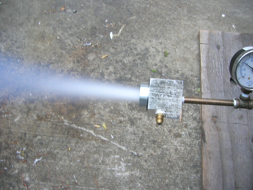 --Steve |
|
|
|
Post by britishrocket on Jun 19, 2013 14:03:21 GMT -5
Hi Steve,
No problem, great to hear from you again. I can see what you mean regarding the spray opacity when using CO2. Despite the opacity of my sprays I did manage to get images of the droplets in the centre of the spray. It took quite a lot of trial and error and different flash positions. I finally discovered that the best method was to use the built in flash on the camera. The all singing all dancing high power flash I'd bought wasn't really needed. You might be surprised by what a fast shutter and a flash can reveal in the centre of your spray.
I think I am going to try to butter up a university engineering department and convince them to let me use their seriously expensive particle sizer with my jury rigged contraptions. Then again, maybe not.
|
|
stevep
Veteran Member
  
Joined: November 2012
Posts: 120
|
Post by stevep on Jun 19, 2013 20:40:39 GMT -5
Here's some work I did a month or so ago on actuated valves. I need valves for both the static testing and the flight configuration so I figured I'd kill two birds with one stone and just use the flight version for the test stand. The flight configuration has to fit inside a 2" (50mm) diameter tube which really cuts down on the options available. The obvious approach would be to use an RC servo to operate a valve but the form factors are all wrong to fit into a 2" tube. The second problem is finding a valve that will withstand the nitrous pressure and is also small enough. Fortunately, valves are rated *very* conservatively, so, given that no human will be anywhere close to the valves when they're under pressure, I can use a valve rated for only several hundred PSI and use up some of the safety margin. I have tested some small valves hydrostatically and they are good to at least 1800 psi, so there appears to be a huge safety margin. The ones I've settled on are 1/4 turn ball valves with a 1/4" orifice. The lightest valves are not easy to mount (they're regular plumbing valves); a model that is a bit heavier is hexagonal in cross-section and with some judicious drilling can be mounted fairly easily. Best of all they cost less than ten bucks each. The seats are PTFE which according to all that I've read is safe for Nitrous. The other issue is finding a gear motor with the right form factor that will turn the valve while not requiring a ton of current to do so. A fairly exhausting search of small motors intended for hobby robots turned up one from solarbotics.com ("GM9") which was less than $10.00. Finally, it is useful to be able to sense the position of the valve. Servos do this by connecting a potentiometer (variable resistor) to the motor and measuring the voltage drop across the pot. It's fairly easy to do the same thing yourself and the cost is only a couple of dollars. Here are the individual parts: 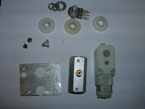 Top row is the potentiometer with mounting washers and nut. Next row down are the gears--they're just cheap plastic ones and I drilled them out to fit the valve, motor, and potentiometer. The valve and motor gears got cross-drilled for a pin to lock them in place on the motor & valve shafts. The potentiometer turns easily enough that a tight friction fit between the gear and the shaft is all that is required. Bottom row is the mounting plate, valve, and gear motor. Here's a photo of everything mounted to the plate:  And here's the same thing from the other side (it's a tight fit): 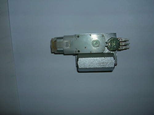 Finally, here's a shot of the whole thing nearly fitting inside a 2" tube: 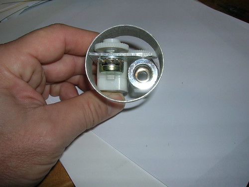 The gears don't quite fit, but because I only need a 1/4 turn, I can cut out parts of the gears and everything will fit fairly easily. I did also have to grind down a bit of the valve--the "points" of the hexagonal body stuck out a bit too far. The motor almost turns the valve with only 3 volts; with 6 volts it really opens/closes it quickly. I don't need much battery capacity since during the flight/testing I only plan to operate the valve a few times. A couple of tiny rechargeable Li-Ion cells will do nicely. Total assembly weighs about 155 grams; with the lighter (but harder to mount valves) I can get it down to about 125--we'll see if I need to do that when I get more of the motor built. --Steve |
|
|
|
Post by britishrocket on Jun 20, 2013 3:21:58 GMT -5
Very nice work with the actuated valve. It is a good idea to have a potentiometer to sense the position. I was intending to use microswitches to just give me open/travelling/closed and vice versa. I can see the potentiometer is a good choice as it gives you a ready made reliable solution in a small footprint. Important from your weight/space restrictions.
|
|
stevep
Veteran Member
  
Joined: November 2012
Posts: 120
|
Post by stevep on Jun 20, 2013 7:03:17 GMT -5
Thanks!
I'd be very wary of microswitches (for any purpose) because of vibration (and, if you were planning to use them in a flight vehicle, g-forces, both planned and unplanned). Not saying they couldn't be made to work, but I'd expect them to be problematic, based on the experiences of the HPR community and others.
--Steve
|
|