|
|
Post by britishrocket on Jun 21, 2013 3:53:57 GMT -5
Interesting point although I have personal experience of them working well in aircraft applications (actuated valves in engine and ancillary systems). That said there is probably going to be a lot more vibration when I fire the engine...Most microswitches have a fairly hefty over centring spring, but you never know. In my work life I've been an advocate of getting rid of pots in favour of hall effect sensors to improve reliability, so maybe that would be the way to go.
|
|
stevep
Veteran Member
  
Joined: November 2012
Posts: 120
|
Post by stevep on Jun 21, 2013 9:11:23 GMT -5
In the HPR community, G-forces are considerably higher than in most aircraft--10s of Gs for example. Sometimes rockets spin, so you can't always assume the direction of the force. Not to mention what happens during off-nominal flights. Hybrid rockets are known for high-vibration levels compared with most solid fuel rockets causing electronics that work fine with solid fuel motors to misbehave in hybrids. Combustion in liquid motors is often erratic during initial testing, so I can imagine vibration levels could be very high.
All I really know is that I've read about problems over the years so I just avoid microswitches. It is true, as you say, that many can have very stiff springs so you could probably find ones that work.
I agree that pots have problems that are often avoided with Hall-effect sensors: dirt and wear being the two common ones. If I have wear problems with my pots, that could be a "good" problem to have as it would mean I'm doing lots of testing/flying :-). Dirt, not so much.
--Steve
|
|
|
|
Post by britishrocket on Jun 22, 2013 3:01:18 GMT -5
Several very good points. I can see now that microswitches could become problematic. It has to be said that your pots are the most cost effective solution to the problem.
|
|
stevep
Veteran Member
  
Joined: November 2012
Posts: 120
|
Post by stevep on Jun 26, 2013 21:21:10 GMT -5
And now, back to something resembling machining--some recent (and not so recent) work on the chamber: After months of consideration (spread over a couple of years), I settled on a regen chamber that uses drilled holes for the coolant passages. I wrote some software to do the cooling calcs and arrived at a passage size of about 1/8" for the length of about a 6" chamber having 6 "up" passages and 6 "down" passages. That is, the coolant (the fuel, kerosene) runs from the injector end down to the nozzle end, then does a U-turn and comes back through a second channel to the injector end whereupon it is injected into the chamber. The chamber walls would be 1/4" thick, allowing me to use stock aluminum tubing for the chamber which means I don't have to waste gobs of aluminum (and time) by machining out the inside of a solid bar. However, it means leaving a scant 0.0625" clearance on both the outside and the inside of the tube. The holes will have to be mighty straight! I tentatively decided on the drilled passages after I tried my hand at brazing cooling tubes onto a chamber and after I tried cutting slots and then shrinking on an outer jacket. Brazing aluminum is apparently doable (in the right hands) if you have a torch that is capable of altering the flame temperature, which I didn't. A straight propane torch of the type used to solder household plumbing simply led to a horrible mess of either globs and gaps of brazing material or burned-through tubing. Shrinking on a jacket requires more, and more uniform heat, than I was able to create with the result that the jacket went on for about one inch, then froze in place. Considered, but yet to be tried, is to machine a 2-part jacket that bolts in place. The usual problem with drilled passages (aside from the fact that they are long (deep)) is that you generally want the coolant to follow the interior of the chamber, in particular where the nozzle narrows down at the throat and then enlarges again toward the rear of the chamber. The throat is where most of the heat is concentrated, so this part tends to be fairly critical. Since drilling these holes at an angle would be problematic, I decided to avoid the problem altogether and use a solid graphite nozzle that would be attached to the end of the cylindrical chamber. Graphite is very heat tolerant and I've been making and using graphite nozzles for my solid rockets so I'm familiar with its properties and how to make nozzles from it. The Armadillo guys made an entire uncooled chamber of graphite, so I figured if I could attach the nozzle to the chamber (with no leaks), I'd be home free for a burn of 30 seconds or so. So the chamber itself would be cooled, but the nozzle hanging off the end would not. As for drilling the passages, some time ago I used the lathe to test drill a long, 1/8" diameter hole in a rectangular aluminum bar. I found that by scribing both ends accurately, mounting it in the 4-jaw, and drilling from both ends with a 6" long drill bit (after starting the hole with a shorter bit), I could get the holes to meet with only a tiny bit of mismatch. In fact, it worked the first time I tried it, leading me to believe that this would be a far less problematic approach than either brazing or shrink fitting. Here are the weapons of choice: 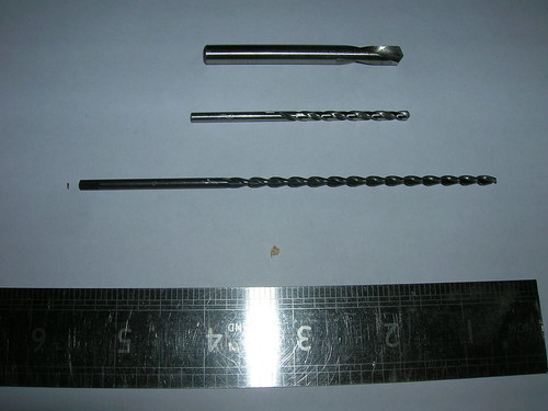 Top item is the spotting drill, 1/4" (6mm) with a 120 degree tip. 2nd item is a 2" long, high-quality 1/8" twist drill, 118 degree tip 3rd item is a 6" long, 1/8" twist drill with a chip-clearing flute design Once I successfully drilled the test hole, I moved on to other issues, and that is where things sat for many months until I recently decided it was time to do some serious work on the chamber. I figured I'd start by working on drilling the coolant passages in the walls of a cylinder. When it comes to using a lathe to drill a cylinder wall (instead of a rectangular bar) some way has to be found to accurately mount the cylindrical chamber off center--this is problematic and becomes much more so when one considers the number of holes to be drilled. That is, you don't want to have to realign for each hole. I solved the problem by making an expanding mandrel with a rectangular base: 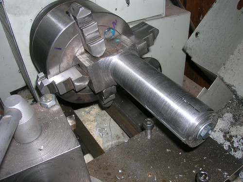 The rectangular base is gripped in the 4-jaw which allows it to be adjusted side-side (whereas if you try to adjust a cylinder side to side you'll quickly come to grief). The cylindrical portion of the mandrel is sized to fit the inside of the chamber with a snug slip fit (for accuracy). In theory, once the mandrel is set up to make one hole, the chamber can simply be rotated around the mandrel to the desired position--no recentering is required. The mandrel is then tightened by turning the screw in the end (the same as any expanding mandrel). Notice that the cylindrical portion is offset on the rectangular base--this is to allow the whole thing to be gripped in my 4-jaw while putting a portion of the wall of the cylinder in line with a drill held in the tailstock (see photo below). I scribed the chamber stock using the lathe--I mounted the chamber stock in the 3-jaw, aligned it carefully, and lightly gouged the surface with the point of a scribe that was held in a tool holder on the carriage which was then moved along the chamber. I then transferred these marks to the ends of the chamber, and, using my dial calipers, marked the center of the wall. This gave me locations for the holes that were likely as accurate as one could ask for. Aligning the mandrel is a time consuming and (for me) aggravating process. There are four alignments that have to be correct: pitch and yaw (to use airplane terms), up-down, and side-side. First, the mandrel has to be aligned axially (pitch and yaw); I allowed for this by finishing the square end of the mandrel nice and flat before machining the cylindrical portion of the mandrel. In theory this would allow me to simply butt the mandrel tightly against the face of the 4-jaw and be assured that it was aligned with the bed of the lathe--at least to within a couple of thou over the 6" or so length. In practice I found I was off by enough that I had to shim the base to get it aligned axially. Aligning the mandrel side-to-side and up-down is more problematic. This is just the usual 4-jaw alignment process except that you have to also maintain the axial alignment. Knowing when you've got it properly aligned is not easy, either, because the true test is where the point of the drill bit ends up and most drill bits don't have an exact point. Since I didn't have a scribe or anything I trusted to have an exact point concentric with the shaft, I simply tapped my spotting drill against the end of the cylinder to leave a mark and trusted that the hole would be within 10 thou or so. This turned out to be a usable, if inexact approach. (Yes, at that point, I should have just removed the 4-jaw, chucked up a piece of mild steel in the 3-jaw and made a decent scribe--after all, I only needed to mark aluminum, so the scribe wouldn't have needed to be anything special. Next time I have the 3-jaw on, I'll try to remember to do that.) Anyway, it *looked* good, so using my 1/4" spotting drill I spotted my first hole. This is when I discovered that I was off by more than I wanted to be. But it looked like I'd still have the needed clearance, so I chucked the short (2") drill and started the hole, lubricating well and backing out often to clear the chips. That part went fairly fast. Then I chucked the 6" drill and repeated the process, but backing out required moving the whole tailstock which slowed things down quite a bit. I think the first hole took 20 minutes or so to drill, but it seemed to go well. Here's the chamber stock mounted on the mandrel; several holes have already been drilled. You can see how offsetting the chamber puts one part of the wall in line with the drill bit. 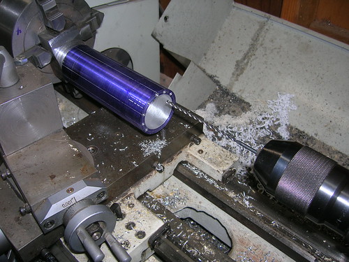 Now for the test of my mandrel idea: I loosened the conical-wedge in the end of the mandrel and twisted the chamber stock until the mark for the next hole lined up with the spotting drill, then I *carefully* tightened the mandrel up again (making sure the chamber stock didn't move). I am pleased to report that the next hole lined up on the marks just exactly the same as the first hole had, so the mandrel *idea* seemed to be workable. What is more, the drill hadn't wandered out through the outside of the cylinder! I drilled a few more holes and somewhere along the line I noticed that it started to get a bit harder to twist the cylinder around the mandrel, but I just used a little more muscle and didn't think anything more about it. The next morning the significance of the harder twisting observation began to sink in, and with some effort I pulled the chamber stock off the mandrel. Sure enough, a couple of holes had wandered through the *inside* of the chamber and gouged up the mandrel pretty deeply. The chamber itself was obviously ruined. At this point I had drilled seven out of the 24 holes (12 cooling holes drilled from each end) that I would need. Two had wandered completely through the chamber wall and a third was close enough to coming through that I could see the "track" of the hole. Drilling longitudinal holes suddenly looked a bit harder :-) At first I thought that the long bit had wandered, but I stuck the short bit in the holes and discovered that the three that had "wandered" had simply not been started straight: 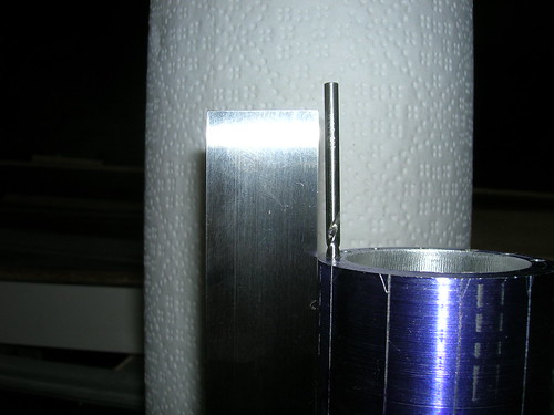 This was relatively good news in that if I could start the holes straight, I probably could get them to stay straight (at least as far as I can tell -- the acid test will be drilling from the other end and seeing how well they meet in the middle). The mystery was why some should start straight (aligned is probably a better term for it) and why 3 should be off by varying amounts. Sadly, I did not drill the holes in any strict order (or, at least I don't know that I did), so I couldn't tell whether the alignment deteriorated over time or whether I somehow just did something at random. I spent some time trying to figure out the reason for some of the holes being angled and tried the following to narrow down the possibilities: bent drill(s)?--nope, looked absolutely straight within the limitations of my measuring equipment. Cutting edges not identical causing the drill(s) to "pull" to one side?--nope, marked the drills and tried rotating them in the chuck to see if it made any difference as to which way the holes were off and couldn't create any misalignment! Did I somehow not get them straight when I put them in the chuck? Tried, but couldn't make it happen without it being easily noticed. At that point I decided that my drilling technique was probably at fault--I had been backing out and clearing the chips "often" but not perfectly regularly and I recalled that sometimes the chips stuck to the drill (the shorter one, the longer one cleared them pretty nicely) and had to be pried off. Since I now had a test piece (the ruined chamber) I drilled a few more holes, backing the short drill out every 1/8" (3mm) and, of course, lubricating each time. I also started the hole with a feather light touch in case I'd been causing the drill to bow or wander as I'd started the hole. I also checked to see whether spotting the hole such that the short drill bit fit completely within the spotted hole made a difference. What I found was that spotting depth seemingly made no difference, but scrupulously backing out every 1/8" with the short bit seemed to fix the problem--I drilled several test holes in a row with no detectable misalignment. I also found that "peck drilling" broke up the swarf and made for easier chip clearing. So....I spent several hours making up a new chamber blank and preparing to start over. At this point it looks like each end of a hole takes about 20 minutes, so with 24 ends, that will be 8 hours. I can only hope I don't ruin too many chambers :-) Stay tuned.... --Steve |
|
|
|
Post by racket on Jun 26, 2013 21:35:52 GMT -5
Hi Steve
Your perseverance is admirable :-)
Cheers
John
|
|
|
|
Post by Johansson on Jun 26, 2013 23:14:25 GMT -5
Hi Steve, Very interesting solution with the mandrel and the 4 jaw chuck, I hope you get it right the next time. Posts like this one makes me warm inside for some strange reason, must be some mechanical nerve that starts resonating.  Cheers! /Anders |
|
|
|
Post by britishrocket on Jun 27, 2013 15:06:33 GMT -5
Interesting job with the mandrel. Just wondering if it would help to start each hole with a centre drill as opposed to a stub drill? Perhaps just that bit more rigidity, and a guide for the jobber drill to find the centre. That said your short pecking with the stub drill seems to have had the same effect.
|
|
|
|
Post by britishrocket on Jun 27, 2013 17:40:49 GMT -5
I have been thinking some more about your problem and here is what I have come up with so far (for what it is worth).
Firstly, even with your four jaw you are on to a loser trying to drill on centre and parallel with so much wide, unsupported and eccentric stock protruding.
I'm assuming you don't have access to a milling machine, but you probably have a pillar drill (drill press). You could obtain a rotary table and an X-Y milling slide and mount these to your pillar drill, then mount your 3 jaw onto the rotary table and index away. But you have probably already thought of this.
The second and lathe based idea is as follows. Obtain a flexible drive unit for a hand held power drill. Fit the driven unit that you fit the drill bit into, and which you normally hold in your hand, onto your toolpost. You might have to come up with some sort of mounting adaptor to do this. Centre the drill bit/drive unit in your toolpost to the lathe centre. You will of course have to mount the power drill in a vice or similar close by so that it can remotely drive the drill bit. You can now fit the chamber or other item requiring peripheral holes into the lathe chuck. You can then index the chuck by counting change gear teeth, or another similar method. There are quite a few of these used for repeat pick up when threading. You can then move your toolpost mounted drill to your PCD, index your workpiece and drill away, using your cross slide or carriage feed to feed the drill.
|
|
stevep
Veteran Member
  
Joined: November 2012
Posts: 120
|
Post by stevep on Jun 27, 2013 19:36:11 GMT -5
Anders, John: Thanks!
Carl: Thanks for thinking about this. I think terminology may once again be confusing the issue. The top drill is a *spotting* drill, not a stub-length drill. Spotting drills are expressly meant for starting holes, unlike center drills which are meant for putting the holes in the ends of workpieces for turning between centers. Yes, I know, center drills *are* widely (mis)used for starting holes, but a true spotting drill is far superior.
I don't think the unsupported length of the mandrel (5") is hurting. It's 1.5" in diameter so it's not going to flex and it's gripped pretty doggone tightly. Also, I'm not applying force *across* it the way I would be if I were shoving a cutting tool into it with the cross slide. Drilling from the end puts very little cross-axis force on it. In fact, I'm now quite certain the mandrel arrangement is fine.
The drill press is far less accurate than the lathe--no way I'd be trying this on a drill press (and you're right, I don't have a mill). The other reason you can't do this on a drill press is that the only way to withdraw a long drill bit all the way out of a hole is to lower the table, whereupon you immediately lose your registration. The lathe works because the tailstock is *meant* to be moved while maintaining the registration.
Re the flex drive unit, here again it just isn't as accurate as the lathe itself. In fact, I have a hand-held drill that I mount directly to the carriage (no flex drive needed) and it is good enough to drill shallow holes, but nowhere near good enough to drill the ones I'm trying to do here.
I hate to give away the ending to the story and I'll probably jinx the next hole by saying this, but at this point on the new chamber, I'm 9 for 9 on the last nine that I've drilled and 11 for 12 overall. The one that wasn't aligned properly was caught before I used the long drill, so the chamber remains intact. Haven't decided what to do about misaligned hole yet--will worry about that when I get the other end done.
Edit: Also, I'm running the lathe down around 100 rpm (slowest it will go). That helps a lot with the eccentric weight issue.
--Steve
|
|
|
|
Post by britishrocket on Jun 28, 2013 2:25:35 GMT -5
No worries, I'm glad you got the holes drilled!
|
|
stevep
Veteran Member
  
Joined: November 2012
Posts: 120
|
Post by stevep on Jul 3, 2013 20:42:18 GMT -5
I started drilling the second chamber thinking I understood what I needed to do to get the holes aligned, but I think there's a variant of Murphy's law to the effect that if a procedure works on the test piece, it will fail on the real thing.
This time I got a little smarter and numbered all the holes and drilled them in numerical order. I also checked for alignment after I used the short drill and before I started drilling with the long one. That way, I might have to abandon a hole that was misaligned, but I likely wouldn't drill through the chamber wall.
As I indicated in my previous post, the first two holes were fine, but somehow the third one got misaligned.
At this point I took to heart something I'd first come across when I learned to cut dovetails in wood: before you start, take a few minutes to put yourself in the frame of mind that you have 1,000 years to do the job. I mean *really* believe it--when you feel in your bones that you can take a full day to make one stroke with the saw, then you're in the right frame of mind.
Being in that frame of mind allows you to drill excruciatingly slowly--after all, you have 1,000 years to drill that hole. In that frame of mind, it's not a hardship to just barely put enough pressure on the tailstock crank to get the smallest possible bit of swarf--you have a 1,000 years to drill the hole. Feel the bit bind a bit? No problem, you have a 1,000 years to drill the hole, so back it out, clean it, lube it, and start again.
This is the total opposite of the frame of mind you'd be in if you dashed off to the shop to "drill a couple of holes before dinner" and were constantly looking at the clock.
After being surprised by the third hole being misaligned, I realized I needed to fine tune my definition of "start the hole carefully". That third hole wasn't quite careful enough, so I upped my "care level" and started the rest of the holes with the lightest touch I could manage. How light is that? Light enough that if I were pushing a pin against a balloon, the balloon wouldn't pop. Light enough that if it were any lighter, the drill wouldn't even cut.
And I really lubed the heck out of the bit. That first 1/8" (3mm) really took some time and I used only the pressure of one finger on the crank; the next 1/8" went a little (but only a little) faster. After I had a half-inch (12 mm) deep hole, I graduated to the pressure of two fingers. I withdrew the bit every 1/8", thoroughly brushed off every chip until it looked absolutely clean, slathered it with oil, and gave it another 1/8". It took some time, but, after all, I had 1,000 years to drill the holes.
That might have been overkill, but the the next 21 ends of holes were all bang on. The long drill bit has "parabolic flutes" (whatever that is) and clears chips better than a regular spiral flute, so I could advance it a whole 1/4" (6mm) at a time before I felt it ever so slightly bind, at which point I withdrew it and cleared the chips. Any time I felt any additional resistance, I'd back the bit out, even if I hadn't reached my arbitrary 1/8" or 1/4" limit for the bit. It seems to have worked. All twelve holes meet in the middle--most have a slight ridge where they don't meet exactly, but I think they'll flow liquid just fine.
I even saved that third hole--I got a longer bit and just continued drilling from the opposite end the extra amount for a total of almost 4" (100mm).
I am now of the opinion, to paraphrase that American icon of malapropisms, Yogi Berra, that doing something like this is "90 percent half mental". Proper frame of mind seems to be essential. But, you know, after all that, the holes still only took about 20 minutes per end--just about the same as when I wasn't being so careful. Maybe there's something to that Zen stuff :-)
Next up: the nozzle and nozzle end of the chamber.
--Steve
|
|
stevep
Veteran Member
  
Joined: November 2012
Posts: 120
|
Post by stevep on Jul 11, 2013 10:57:43 GMT -5
Here's the aft-end of the chamber, consisting of the chamber itself, a gasket (currently EPDM rubber), the graphite nozzle, a ring that bears on the collar of the nozzle, and the machine screws that hold it all together.  Here's the thing assembled. If you look closely you can see the gasket between the nozzle and the end of the chamber. Just barely visible are a couple of the heads of the socket head machine screws. 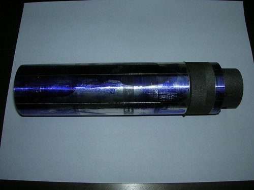 Here's a view looking at the aft end, showing the divergent section of the nozzle and the socket heads of the machine screws holding it all together. The divergent half-angle is 12 degrees, the expansion ratio (exit area divided by throat area) is about 5:1. Throat is about 0.44" (11 mm) in diameter. 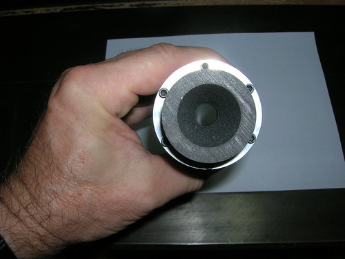 Here's a closeup of the aft end of the chamber with the machine screws in place. You can see the slots that connect adjacent pairs of cooling channels--these slots form the bottom of the "U" that allows the coolant to flow from the injector toward the aft end, make the U-turn, and flow back up toward the injector. There's plenty of swarf to be cleaned out; this was photographed pretty much straight from the lathe. I do have some concern that I haven't left much surface for the gasket to bear on. This may prove to be a source of leaks but I can't easily test that until I get the injector partially made. During my drop size testing I had some configurations with about that amount of bearing surface and with enough clamping pressure, they seemed to hold pretty well. We'll see. Plan "B" is to use 3/8" (9mm) wall tubing instead of 1/4" (6mm) which will make the chamber heavier and require more machining but would give me quite a bit more bearing surface. 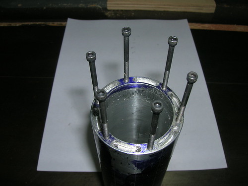 Here's a shot of the graphite nozzle from the side. I use "medium grain" graphite because it's readily available (usually) and is fairly cheap--a 2" (50 mm) long, 2" diameter piece is about $2.00 which is less than I pay for a chunk of steel that size. 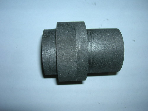 Here's the convergent end. The half-angle is about 30 degrees. The outer diameter of the convergent end is a firm slip fit into the chamber which should protect the gasket from direct flame. You can see how nicely the graphite finishes--no sanding was done. Turning graphite is messy but easy. I use a shop vacuum with a shop-made narrow nozzle positioned right at the cutter to remove the dust during machining. There's still some cleanup to do but the vacuum gets most of it. Graphite is electrically conductive so that's another reason you really don't want it floating around the shop. 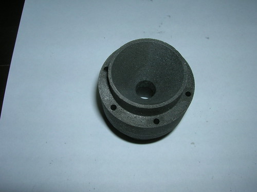 Here are some photos of how I dealt with the aft end of the chamber, given that I don't have a mill. First, I mount my "poor man's dividing head". This is similar to many gear-based solutions you can find on the net, except that mine is not permanently mounted. If you haven't seen these before, there's a shop-made expanding mandrel that fits inside the spindle. The gear is fastened (tightly) to the expanding mandrel. The index pin is ground to fit tightly between the gear teeth and tightened with the knob. This has to be repeatable, but not terribly resistant to torque since not much torque is ever applied to the work piece. 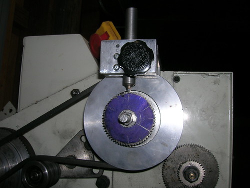 Here's a shot of the top bracket that holds everything in place. The machine screws on the right end tighten it in place. You can see that the index pin rides in a slot (not a round hole) formed by the two vertical pieces at the end. I first tried a hole but getting the pin to not move and to be repeatable proved to be difficult so I changed to the slot. The corners of the slot grip the pin very tightly and there is virtually no movement once everything is hand-tight. 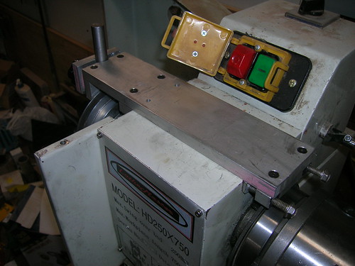 Here's a photo of my drilling setup. I bought this drill just for this purpose--it has a nose that is round (many drills don't have this) which makes it easy to mount. The case is hard plastic which I thought might not be rigid enough, but for drilling short holes and light milling it seems to be fine. Someday I hope to make a spindle and do this "right" but this works surprisingly well for what I've been using it for. Alignment is a bit fussy, but once you get the hang of it, it's straightforward. I use a 3/8" precision ground rod which I chuck in the drill, and a dial test indicator mounted such that when I run the carriage back and forth I can tell how much off-axis things are. I stop adjusting when it's within a thou or two (.03-.05 mm) over an inch or two (25-50 mm) of travel. 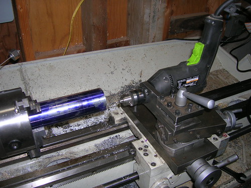 Here's how I tapped the holes (by hand, the drill is just used for positioning). Nothing new here. Once the holes were tapped, I needed to mill the slots for the U-turn. Using this same setup with the drill I chucked a 1/8" end mill in the drill (yes, I know you should use a collet, but....) and rotated the headstock back and forth by hand. I took very light cuts, about 0.020 (.5mm) deep and with a very slow feed rate. Took about 7 passes or so for each slot, but things went well. 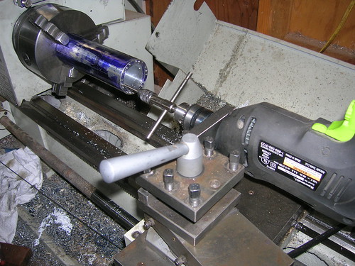 Next up is the injector, but I think that will have to wait for a couple of weeks while I attend to some house building projects. Meanwhile, I'm doing a lot of thinking about the data collection and control aspects of the static test stand. There's an amazing amount of stuff to be done--I've collected a lot of parts and have some rough designs done for several of the printed circuit boards. More news on that as I get a bit closer to having something to show. --Steve |
|
|
|
Post by Johansson on Jul 14, 2013 15:14:44 GMT -5
Very clever setup in the lathe!
|
|
stevep
Veteran Member
  
Joined: November 2012
Posts: 120
|
Post by stevep on Aug 12, 2013 21:32:29 GMT -5
Thanks Anders! Coming from someone with your skills & knowledge I'll take that as a real compliment!
--Steve
|
|
stevep
Veteran Member
  
Joined: November 2012
Posts: 120
|
Post by stevep on Aug 12, 2013 21:50:42 GMT -5
While working on my house, I haven't had many daylight hours to devote to rocketry, but electronics and thinking can be done in the wee hours, so work has been progressing on the test stand controller/data collector. There's still a lot of thinking to be done, but I have fleshed out the controller design to the point where I have the following printed circuit boards (PCBs) identified: - main: master control, contains a micro-controller and associated parts - valve control: contains a micro and runs the motors that control the nitrous and fuel valves while monitoring the potentiometers to establish the position of the valve. A board similar to this one will be on the flight vehicle, so I plan to make double use of at least the design if not the board itself. - pressure monitoring: I was able to get 4 pressure transducers cheaply on EBay; this board will contain the A/D converter chips and also produce the voltage to run the transducers - main nitrous valve control: I have decided to remotely operate the main valve on the nitrous tank; this board will do that. It will also be used when filling the flight vehicle. - igniter: I went back and forth over whether to use a pyrotechnic igniter or an electronic one. Electronic won out and this board will help produce the spark from the automotive ignition coil. - load cell monitoring: load cells will be used to measure thrust (obviously) but also the mass (weight) of the nitrous and fuel tanks. This is easier and cheaper than messing with flow meters and I think will be accurate enough. One board will suffice for all required load cells. - remote communication: I have pretty much decided that the main controller will sit on the test stand (suitably protected, of course) and a small, remote unit will be used to initiate the test and for "emergency stop". This part requires much more thought, but for now, that's the path I'm heading down. I'm keeping everything very modular so if one thing needs to change I don't have to redo everything. The physical layout is designed to make it easy to change/troubleshoot. The box will be larger than if I stacked everything compactly, but space isn't an issue and the box only needs to be about 12" x 12" (30 cm x 30 cm) which is still pretty compact. I'm also not planning to incorporate video, which should help keep things relatively simple. The process for each board is roughly this: identify the requirements, select the parts, roughly lay out the PCB, get the parts, bread board the circuit and test it, finalize the PCB, print and etch the PCB (I do this myself at home, rather than send it out), solder it up, and test it. I have found over the years that it's almost as much work to get the mechanical aspects nailed down as it is to get the electronic parts to work--in this case, connectors to the sensors/motors are the hard part. They need to be robust/reliable, impossible to mis-connect, cheap, and obtainable. There are literally tens of thousands of connectors to choose from, so it's been a lot of work to sort that part out. If you think this part is easy, have a look at Armadillo's blog to see the problems they had with connectors (true, their parts were actually in flight, but test stands can vibrate, too, so I've taken their experiences to heart). I've been working on most of the boards simultaneously, but the one that I've focussed on primarily is the igniter board. I wanted to get it done first so that I could use it to see how much it might interfere with the other electronics. I've never worked with an automotive coil before, so I had some learning to do there, but thanks to the internet there are plenty of hints (and some horrible mis-information) about using them. There wasn't an exact recipe and plenty of experimentation was required to get the spark and the electronics to be robust, but it wasn't conceptually difficult--just a matter of swapping components until the right values were found. Here's the breadboarded version (the black blob in the back is the coil): 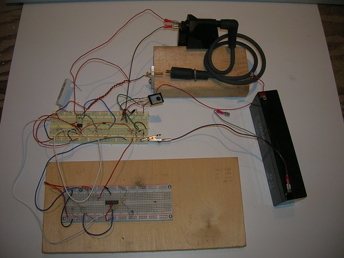 And here's the very nice spark that it produces: 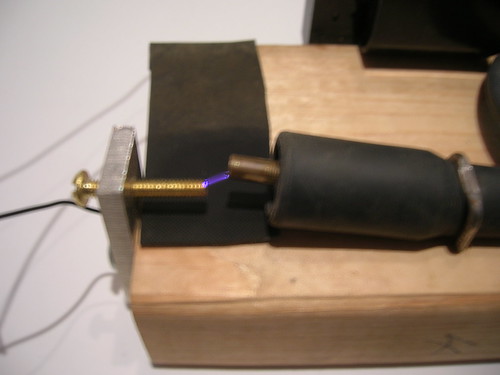 Sorry about the blur, but with the flash, the spark didn't show up. The gap is about 0.3" (5mm), but (as you can see) it can be adjusted. I've made sparks jump a gap of almost an inch (25mm) but they get pretty weak at that distance. I'm sorta shooting in the dark here because I don't really know what's required to ignite the nitrous, but based on what others have done, it seems like what I have here should do the job. There wasn't a lot of challenge to this board beyond the fact that semi-conductors don't appreciate being bombarded with high voltage spikes--these days, though, it's fairly easy to find very high-voltage, robust parts. The second part of the effort was to devise a circuit that would fairly reliably detect whether a spark was in fact being produced. I found an easy way to sense whether any current was flowing in the high-voltage lead from the coil so that's what I'm going to be doing. It's not foolproof, but the spark generator itself seems to be very reliable so the spark-detection circuit is probably almost redundant and therefore being absolutely foolproof probably isn't required. If you're curious, the board in the back of the photo creates the spark, the board in the front is the circuit that detects the spark. I've got the PCB for the igniter laid out and almost ready to be printed and etched. Some of the other boards are coming along nicely: the valve controller is laid out, I just need to breadboard it to verify that I'm not doing anything stupid and to test whether the igniter will cause too much interference. The pressure transducer board has been a bear (mechanical stuff, mostly)--but I have parts of it breadboarded and working. More on that one in a future post. The load cell board should be easy--I've done that sort of thing before. Main nitrous valve board is going to be interesting--the motor will be large (and take a couple of amps) so controlling it could be fun. I've selected a windshield wiper motor and I think that the chip that runs the valve motors will also handle the wiper motor, so I *think* I'm OK there, but will need to breadboard it to verify that. I'll test it on my CO2 tank. The main board and the remote communication boards will wait until I have more of the subsidiary boards laid out or built. I have the inter-board communication scheme (and connectors) figured out, and the other boards have been designed to make the main board's job as easy as possible, so I don't expect too many surprises when it comes to the main board. The remote communication is mostly about what method to use (wireless, wired, protocol, etc); probably some testing will be in order before I can decide on all that. As things progress, I'll provide summary updates, but won't go into the details of the circuits unless someone is interested, since I am under the impression (perhaps incorrectly) that people here are not electronics enthusiasts. I'm happy to answer questions, though, so if you want details either reply or send me a PM (now or in the distant future). --Steve |
|