|
|
Post by propellanttech on Oct 27, 2011 10:32:50 GMT -5
you could also use CO2 to pressurise the fuel (similar bottle pressure to N2O, liquid storage, etc) The problem I see with this, is an extra tank (more weight), and the NO2 is still going to be used to help pressurize. It will decompose as well to help keep up with the pressure drop. This is due to the thermal component the CO2 will take on when expanding. It will slow down as it gets cold, then the NO2 will begin decomposing to keep the pressure up. There will eventually be a balance, but it may be at the end of the burn before that happens. If that is going to happen, just use the NO2 in the beginning. NO2 is quite safe in it's vapor state. Although you do not want to mix NO2 liquid with anything. That would spell disaster. James |
|
|
|
Post by Johansson on Oct 27, 2011 11:02:19 GMT -5
What about using a soda streamer CO2 bottle for fuel pressurizing? Cheap, lightweight and easy to refill just about everywhere.
The nitrous oxide can pressurize itself, a heat blanket can be used to alter the nitrous pressure to some extent.
|
|
wolfdragon
Senior Member
  
Joined: April 2011
Posts: 287
|
Post by wolfdragon on Oct 27, 2011 11:43:03 GMT -5
About the full pressure safety factor statement
You need a relief valve downstream of the regulator that can vent the full flow of the tank thus you cannot build pressure downstream thus you do not have to make everything so robust.
Think of it like an aircompressor at home, the tank relief valve needs to be able to flow the rated cfm of the compressor discharge at the relief pressure or the tank will just keep building pressure at a slower rate than before the valve popped.
|
|
|
|
Post by propellanttech on Oct 27, 2011 21:07:11 GMT -5
About the full pressure safety factor statement You need a relief valve downstream of the regulator that can vent the full flow of the tank thus you cannot build pressure downstream thus you do not have to make everything so robust. Think of it like an aircompressor at home, the tank relief valve needs to be able to flow the rated cfm of the compressor discharge at the relief pressure or the tank will just keep building pressure at a slower rate than before the valve popped. With rocket motors, especially, the KISS approach is the best way (keep it simple stupid). The relief valve is just another item to add weight and possibly fail. It is still a practiced approach to make sure the down stream items can take the full pressure. This is the RRS standard, and what appropriate groups recommend. This would definitely be the case with something I may be in close proximity to when it is running. If something goes wrong, I won't become a Darwin award recipient. James |
|
|
|
Post by propellanttech on Oct 27, 2011 21:12:35 GMT -5
What about using a soda streamer CO2 bottle for fuel pressurizing? Cheap, lightweight and easy to refill just about everywhere. The nitrous oxide can pressurize itself, a heat blanket can be used to alter the nitrous pressure to some extent. Not sure about the soda streamer, can't say I know much about the volume of the units. Still I would insure the items can take the pressure. But still, it's not my balls which possibly could be flaming or fragmented. ;D I'm not saying your ideas are wrong, just not the course I would take. James |
|
|
|
Post by Johansson on Oct 28, 2011 7:05:01 GMT -5
The oxidizer and fuel tank will be designed to hold several times the vapour pressure of the N2O and CO2, built from thick pressure vessel steel. Weight won´t be an issue here since it should never leave the ground, if it does well then we are in trouble... ;D Don´t get me wrong, I am very glad that you are giving me lots of ideas and suggestions. That way I can sort out the goodies and do the rest my own way.  |
|
|
|
Post by propellanttech on Oct 28, 2011 15:37:16 GMT -5
The oxidizer and fuel tank will be designed to hold several times the vapour pressure of the N2O and CO2, built from thick pressure vessel steel. Weight won´t be an issue here since it should never leave the ground, if it does well then we are in trouble... ;D Don´t get me wrong, I am very glad that you are giving me lots of ideas and suggestions. That way I can sort out the goodies and do the rest my own way.  Weight is always an issue, just less of one with a kick. Pushing a 3000lb (1360Kg) kick would take some serious thrust to get it moving. Once moving it would continue to accelerate though. So as long as you don't over do it, the weight shouldn't be too much of a problem. As for leaving the ground, I would put a degree maybe two of nose down (nozzle up) angle on the thrust line of the engine. Better safe than sorry. That will tend to push a little harder on the front of the skids (skates??) but should provide a safe down force should the speed become significant. The fist kick into space (or impacting a commercial aircraft) would definitely be a news headline.  James |
|
|
|
Post by Johansson on Oct 29, 2011 0:53:13 GMT -5
I don´t think this engine will find its way to a kick frame, even we consider having a 1000N homebuilt bipropellant rocket engine between the legs a bit too daft...  Some sort of ice yacht would be better where a steel plate can separate the driver and engine in case it blows up on us. The weight issue is not an issue in this case, the driver and frame will by far be the two heaviest parts on the vehicle even if we build the tanks with a 10x safety margin. The whole engine will consist of two <5L steel tanks, a small CO2 bottle, some steel tubes, ball valves and the engine. It cannot weigh more than 30-40kg when finished. In case we want to build something flight worthy later the tanks and engine casing will be aluminum since the rocket will be remotely fuelled and launched and not having some idiot strapped to it. ;D |
|
|
|
Post by Johansson on Oct 29, 2011 7:59:26 GMT -5
I had to reconsider the engine design somewhat since it was very difficult to say the least to reach inside the engine with the lathe tools to make the convergent section of the nozzle, so I cut the combustion chamber part away and made the nozzle a single piece instead. 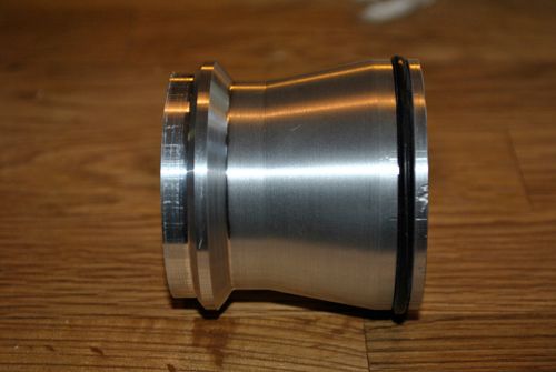 The O-ring will seal against the cooling jacket and allow the aluminum engine core to expand freely once it starts to heat up, it will be fixed to a mounting plate at the injector end. 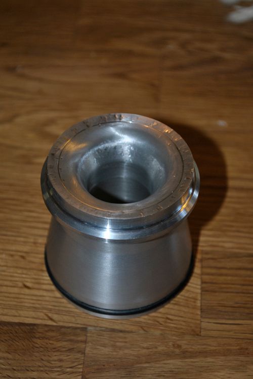 The convergent part, only roughly made yet. Later on the engine internals will be polished to get as little heat transfer as possible into the aluminum. 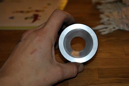 The 25mm throat and the 45mm nozzle exit. The combustion chamber will be made from a thick walled aluminum tube that is welded to the nozzle, this way we can chose to use a longer CC for the initial tests and shorten it later we find that the combustion is completed well before the nozzle. Some thermal paint would be interesting to use here. I don´t know if I should make simple cooling fins on the nozzle, easy to do on the lathe and it can almost double the area exposed to the methanol for better cooling. Cheers! |
|
|
|
Post by propellanttech on Oct 29, 2011 14:16:06 GMT -5
You may want to consider a graphite convergence section for the nozzle. Not sure if aluminum will handle the heat without melting.
It would conduct heat, but could be slow enough to allow the inner part to melt, making the throat gradually larger as the engine burns.
A graphite convergence would insulate the forward section enough to give the heat time to conduct, and also give an ablative surface. Easy enough to replace, and pretty cheap.
If not, the aluminum would need to be pretty thin to allow the regenerative cooling to do the job. Can't tell thickness from the pictures. The forward throat is usually the hardest part to keep cool.
Nice so far though. ;D
Ice sled.......interesting idea.
James
|
|
|
|
Post by Johansson on Oct 30, 2011 2:43:21 GMT -5
I´ve been thinking about the wall thickness, how thin can I go without affecting the strenght of the chamber? I can decide freely how deep I make the cooling fins, and it is no use to make the wall thicker than what is needed.
I have a couple of buckets of cheramic coating left from the JU-01 build so the first thing I could do is to coat the inside of the nozzle, I would be surprised if it doesen´t burn away but since we are aiming at a total burn time of 5-6 seconds it would help a lot even if it only stays in place for a second or two.
|
|
wolfdragon
Senior Member
  
Joined: April 2011
Posts: 287
|
Post by wolfdragon on Oct 31, 2011 7:53:58 GMT -5
Anders,
If you know what your chamber pressure will be, you should be able to size the wall based on "hoop stress equation" and your factor of safety.
As for the nozzle, graphite or even ceramic would be nice since you could just make the AL have a countersunk pocket for the CV/DV nozzle it sit in. Then you could use a stainless snap ring or even a little RTV just to hold it in place before the run. That way if it does burn it out, you have an easy to replace part rather than having to machine a new bigger chunk of material.
|
|
|
|
Post by Johansson on Oct 31, 2011 9:50:05 GMT -5
I have no clue what chamber pressure to expect to be honest, I am working my way through a brick sized rocket engine design book but so far I haven´t found any simple way to estimate it.
The fuel and oxidizer will be fed to the CC at 60bar (nitrous oxide vapour pressure @ 20°C) but I don´t know how the nozzle throat size will affect the chamber pressure.
A graphite or cheramic CD nozzle would probably be a better choice than aluminum, but I´ll give this one a go and see how it endures. Machining a new nozzle is no problem if it takes damage but if that happens I will have to try other materials since we need a reliable and reusable engine.
|
|
wolfdragon
Senior Member
  
Joined: April 2011
Posts: 287
|
Post by wolfdragon on Oct 31, 2011 15:40:25 GMT -5
I've got a few books here from my college days (Aerospace Engineer). I know I have an equation for chamber pressure in one of them... will hunt through them for you.
|
|
|
|
Post by Johansson on Oct 31, 2011 17:02:35 GMT -5
That would be very kind of you! Today I made the injector plate blank, the CC and started making the base plate. The combustor chamber is 190mm long so it should be enough for complete mixing of the NOX and methanol. 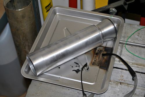 The injectors will most likely be "unlike-doublet impingment jets" where two holes are drilled so the liquid NOX and methanol jets meet at a 60° angle and end up as a fine mist. A series of these injectors will be drilled 360° around the injector plate so a central hole can provide the NOX and a circular chamber sealed with O-rings will house the methanol. 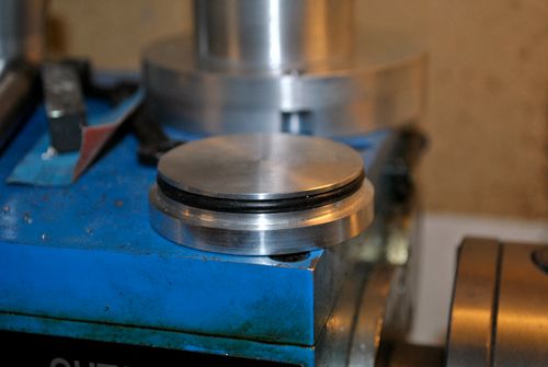 After doing some math I have found that the engine will consume roughly 1.0L of methanol during a 10s run and 3.5L of liquid NOX, so the NOX injectors will have to be 3.5 times larger than the fuel injectors. 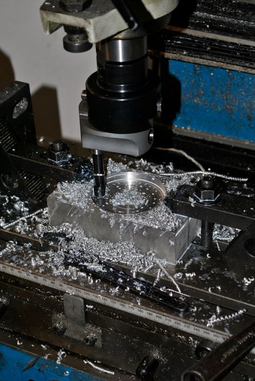 I used my line-boring tool to make a hole in the base plate where the cooling jacket and injector plate will sit. Here is the engine and cooling jacket fitted to the base plate. 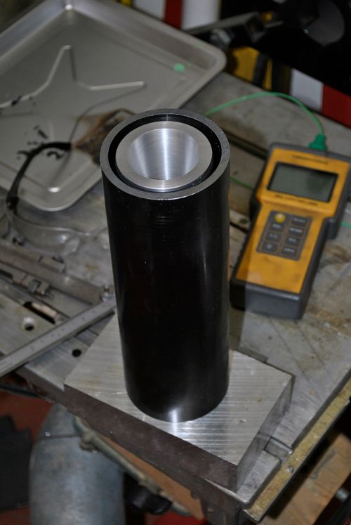 As you can see there is quite a gap between the nozzle and jacket, I will make a steel ring on the lathe later that fits in the gap and weld it to the jacket. 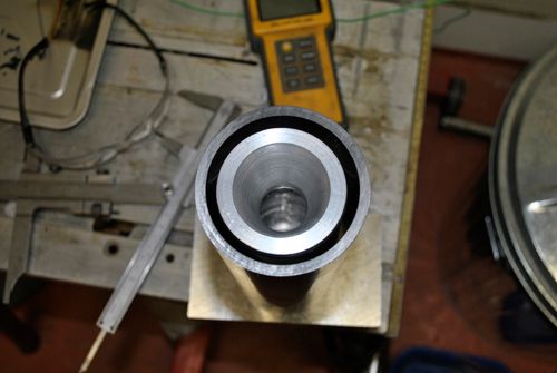 Cheers! |
|