|
|
Post by Johansson on Nov 6, 2011 15:01:17 GMT -5
I´ve reconsidered the injector type and have decided to use a spray nozzle for the fuel and impinging holes for the NOX, HAGO makes high flow hollow cone nozzles up to 120GPH so I´ve emailed Danfoss who sells them and asked about pricing for a range of nozzles from 60GPH and up. With 80° angle and a full circle of 1mm NOX jets entering the base of the spray cone the mixing should be as good as it gets, the methanol spray angle should also provide some extra wall cooling as there will be a liquid film of fuel at least in the upper half of the combustion chamber. I´ve also bought a CO2 bottle so once I have the injector plate made I can start doing some water tests to find out if my assumptions about the mixing was correct or not. Fun fun fun!  |
|
|
|
Post by Richard OConnell on Nov 6, 2011 23:09:46 GMT -5
You're going to help me build an Iron Man suit, right?  |
|
|
|
Post by Johansson on Nov 9, 2011 10:56:08 GMT -5
You're going to help me build an Iron Man suit, right?  Hell yeah!  |
|
|
|
Post by Johansson on Dec 27, 2011 14:50:44 GMT -5
Finally I found some time to continue working on the rocket engine, I will try a nozzle design where a countersunk M6 bolt acts as a 360° fuel nozzle and a full circle of small holes around the bolt head injects the nitrous oxide into the fuel spray cone. 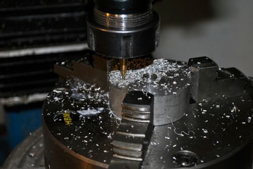 A seat similar to the ones 4 stroke valves is cut into the injector plate, a chamber for the fuel is directly behind it and a hole though which the methanol is fed from the space between the aluminum engine body and the steel casing. 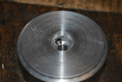 The countersunk bolt is then fitted and the idea is that I can adjust the flow by moving the bolt head closer to or further away from the seat. 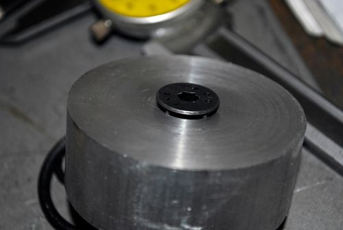 Below is a picture of the upper side of the injector plate, two O-ring slots are milled in it to seal the area where the N2O is. A 6mm deep ditch is milled where the N2O injection hole circle will be drilled. 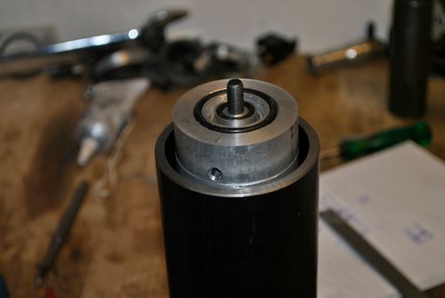 So far so good, but one thing I don´t know is what chamber pressure to expect. The N2O will be self pressurizing and the methanol tank will be pressurized by a CO2 bottle, but I haven´g got a clue how to calculate/estimate the chamber pressure. Since I don´t know the pressure inside the engine I don´t know what the pressure drop over the injectors will be, therefore it is impossible to size the injectors without doing some serious guessing and R&D.  Any help is therefore greatly appreciated, the methanol flow will be 6.5L/min and the N2O flow 20.5L/min. It is the N2O injectors I need to know before making them since they aren´t adjustable like the fuel injector. Cheers! |
|
|
|
Post by racket on Dec 27, 2011 16:56:58 GMT -5
Hi Anders
The table I have in my rocket book has combustion chamber lower pressures at 300 psi ~20 bar with jet velocities of ~7,000 ft/sec , the higher 500psi ones have ~10,000 ft/sec , but for a low speed vehicle I can't see why you'd need such velocities , an enormous waste of kinetic energy .
Mmmmm, more research required :-)
Cheers
John
|
|
wolfdragon
Senior Member
  
Joined: April 2011
Posts: 287
|
Post by wolfdragon on Dec 27, 2011 17:31:23 GMT -5
no joy on the chamber pressure calc, all the books I have just give them
|
|
|
|
Post by Johansson on Dec 27, 2011 17:46:49 GMT -5
So lets say I will have a chamber pressure of 20 bar, N20 vapour pressure at +10°C is 50 bar give or take a bar or two. The pressure drop will be 30bar over the injectors in that case. Since pressure has to quadruple to double the flow I should be able to use a test pressure of 7.5 bar and try to get half the needed flow through the injectors, i.e. 10L/min. That way I can use my shop air for testing instead of having to use regulated pressure from my scuba tank. Here are some more pics of todays work, the last pics were from yesterday. 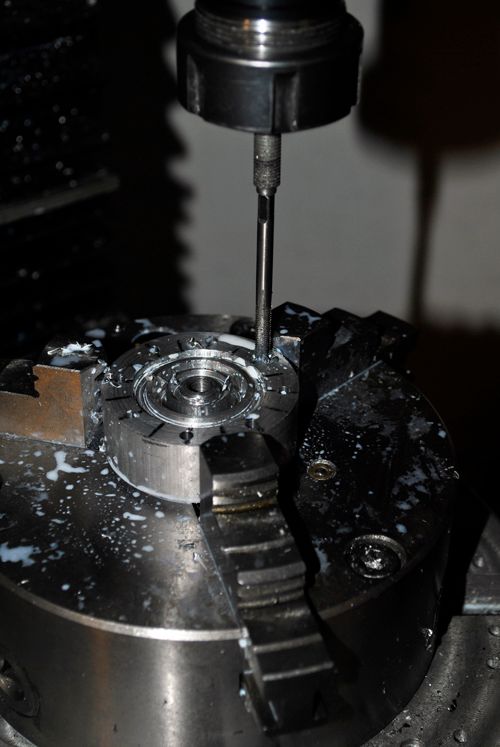 I drilled and tapped the injector plate and made a steel lid for it where the N2O fitting will be fitted, as you can see one of the bolts are missing and that is because I will make a threaded coupling for a pressure gauge and fit there so I can monitor chamber pressure. 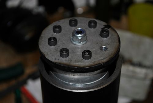 Here you can see the hole for measuring the chamber pressure. 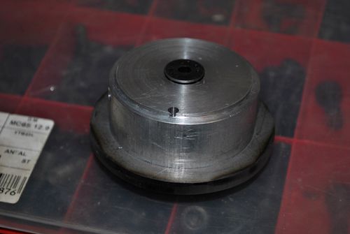 I bought a set of 3" V-band clamps with flanges that will be used for the rocket engine, the steel plate is made to fit inside one of the flanges and will be welded to it once I have tested everything. 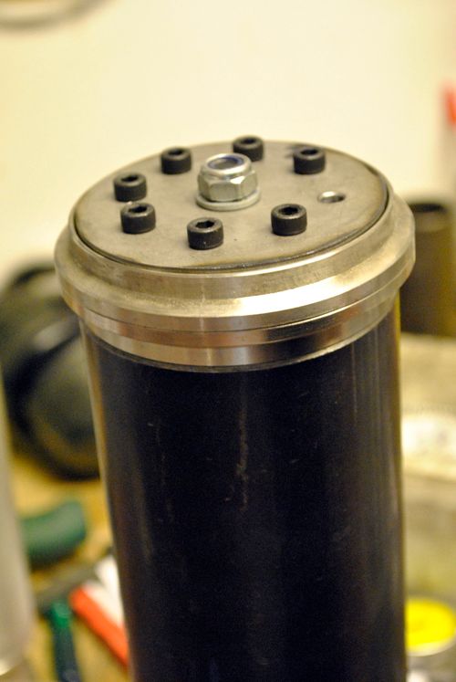 Cheers! |
|
|
|
Post by Richard OConnell on Dec 28, 2011 12:08:46 GMT -5
Very nice Anders, Rockets are fun  I don't even know where to start crunching numbers on something like this.. Best of luck! |
|
|
|
Post by Johansson on Dec 30, 2011 15:14:29 GMT -5
Thanks, it will be great fun to finally test it once it is finished. I have lots of aluminum so it won´t be very disappointing if it melts but the regenerative cooling should see to that it won´t happen. 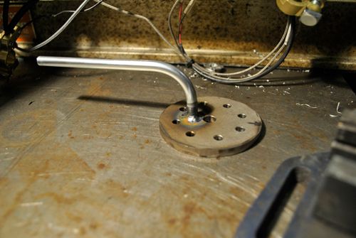 I drilled a hole in the steel cover, bent and welded a hydrulic tube to it which will be the N2O feed pipe to the engine. Once I have test flowed a 1.5mm hole with the same lenght as the ones in the injector plate will be I can drill those as well. I also bought a 16 bar pressure gauge with a high pressure connection tube, the next step up in pressure gauges is 50 bar which is a bit to high at this point. We will start at lower feed pressures (cool bottles) and see how the engine holds up and move on from there. No use going for 50 bar combustion pressure directly and melt/blow up the engine...  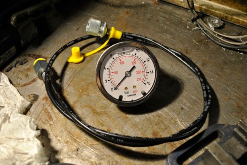 Cheers! |
|
|
|
Post by Johansson on Jan 3, 2012 17:49:21 GMT -5
Today I got lots of stuff made on the rocket engine, it looks like one now at least.  The injector plate was welded and a connection for the chamber pressure gauge was fitted to it. 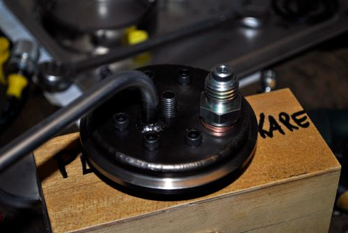 A matching V-band flange was welded to the engine cover after some imaginative milling since my undersized lathe didn´t bite over the cover... 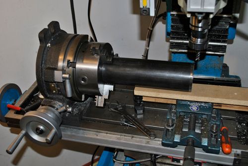 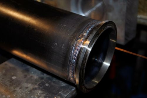 The methanol connection was fitted to the engine cover as well, it is placed so the fuel entering the space between the engine and cover blows directly at the nozzle throat since that section will see lots of heat during the run. 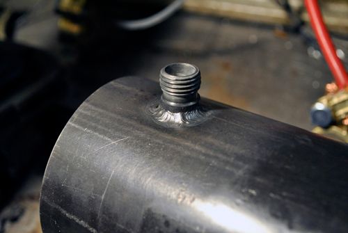 Here is the engine core fitted together, it will have small cooling fins cut over the entire lenght and especially at the nozzle to assist the heat transfer from the fuel to the aluminum. The three aluminum parts (injector, CC and nozzle) will be welded together once they are ready for assembling. 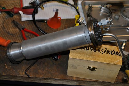 A shot in better light with the engine cover in place, sure looks like a rocket engine now!  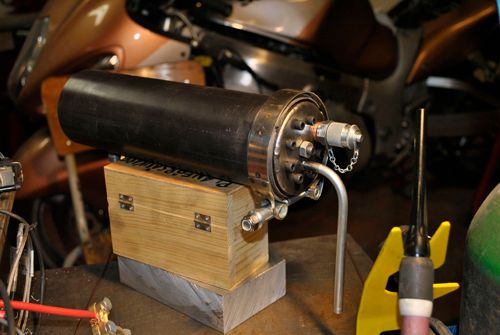 A view from the hot side. 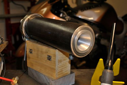 Cheers! |
|
smithy
Member
 
Joined: August 2010
Posts: 31
|
Post by smithy on Jan 3, 2012 20:47:32 GMT -5
Hi Anders,
I wish I had your welding equipment and skills, would come in very handy in my shed.!! ;D
Cheers,
Smithy.
|
|
|
|
Post by racket on Jan 3, 2012 22:08:11 GMT -5
Hi Smithy
LOL........in mine too :-)
Lookin' good Anders .
Cheers
John
|
|
|
|
Post by Johansson on Jan 4, 2012 1:15:18 GMT -5
A tig welder is a must have item, don´t know what I would do without it.  |
|
|
|
Post by enginewhisperer on Jan 4, 2012 3:52:03 GMT -5
anything that can't be TIG welded isn't worth joining together  |
|
|
|
Post by Johansson on Jan 6, 2012 2:23:13 GMT -5
Last night I started making the engine mounts, a circular saw is priceless for cutting thick aluminum as long as you don´t get your fingers in the way. 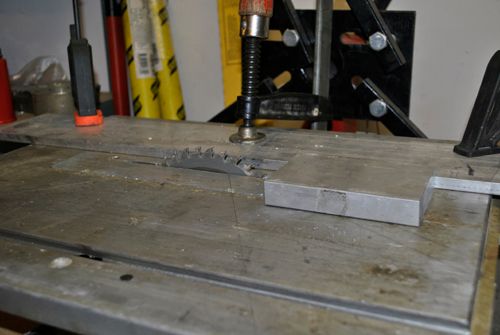 After some cutting I had the four pieces needed to make two engine mounts.  Next job was to drill the bolt holes in the top caps (right word?) and countersink the holes for M8 insex bolts. 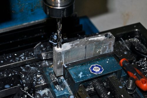 Then I cut the corners off the top caps to improve the looks somewhat, again the circular saw did a splendid job! 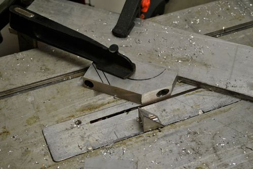 Here they are without corners, now I have to drill and tap the bottom mounts and bolt them together so I can mill the hole for the engine. 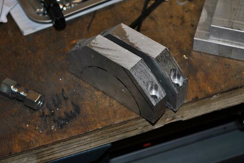 I also made the feed line for the methanol fuel, the two lines will be fitted to pneumatically controlled ball valves so we can run the engine from a presumably safe distance.  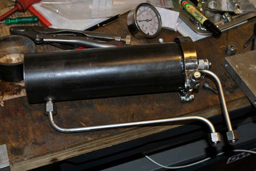 Cheers! |
|