|
|
Post by racket on Apr 5, 2011 18:20:32 GMT -5
Hi Anders
Mmmm , you might need to check axial distances for the inner wall length, .......and allow a few millimetres of "expansion" room so that the 165mm ring doesn't project over into the NGV inlet once things heat up .
An interesting alternative to bending up the inner rear wall :-))
Cheers
John
|
|
|
|
Post by Johansson on Apr 6, 2011 0:39:14 GMT -5
Hi Anders Mmmm , you might need to check axial distances for the inner wall length, .......and allow a few millimetres of "expansion" room so that the 165mm ring doesn't project over into the NGV inlet once things heat up . An interesting alternative to bending up the inner rear wall :-)) Cheers John Hi John! There is no risk that the 165mm ring will go any further into the NGV inlet, the top of the NGV vanes are making sure of that. =) I figure the outer wall will expand more thus making the ring move towards the comp a couple of mm´s, but perhaps I should leave some room in that direction as well. |
|
|
|
Post by racket on Apr 6, 2011 1:05:20 GMT -5
Hi Anders
Ah , good one , your NGVs project a little higher than in my design :-)
I've always found that the inner wall seems to get the hottest , possibly because it has less surface area than the outer wall and the "same??" radiant heat is "concentrated " onto the inner wall ,.......... allow for a few millimetres of potential movement , a bad hot start could expand the FT by that much and it could buckle if theres no room :-(
Cheers
John
|
|
|
|
Post by Johansson on Apr 6, 2011 1:26:17 GMT -5
Roger that, I´m heading off to the workshop in an hour so I´ll make sure to cut a couple of mm´s off the NGV ring before I weld the FT together.  |
|
|
|
Post by Johansson on Apr 6, 2011 11:58:05 GMT -5
Today I finished the combustor, all that is left is to drill 9 mounting holes. 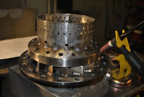 After some fine grinding and bending the inner wall was welded to the front wall, after that a row of holes was bent to direct the air towards the front wall. 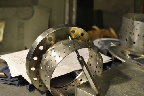 This is what the bent holes looks like. 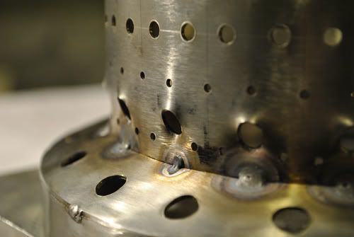 After that I made a tool to bellmouth the row of dillution holes. 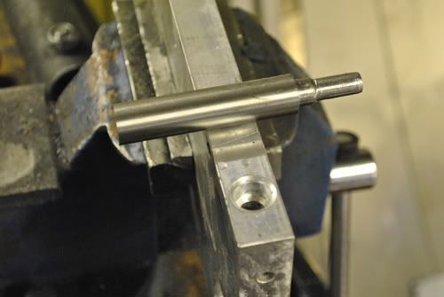 Bellmouthing in action. 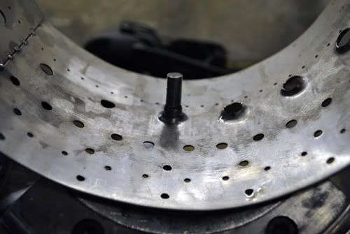 Now it was time to weld the outer wall to the front lid and inner wall. 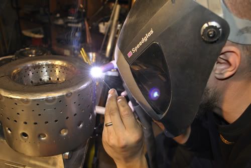 With the combustor welded together I could take a measurement and trim down the outer wall to the right lenght, 9 lips were left uncut and will be drilled for M6 bolts later. 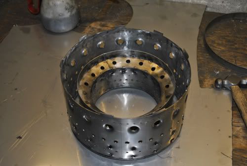 Here is a closeup of the outer wall with the bellmouthed holes and two rows of bent holes just downstream the front wall, the holes are directed so they provide rotation and recirculation in the primary zone. 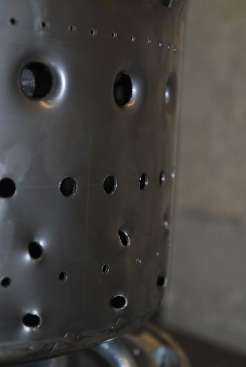 Here is a pic of the combustor fitted on the NGV. 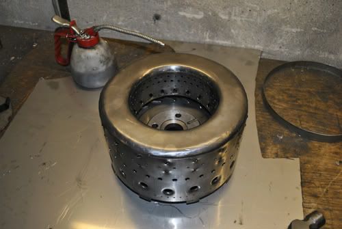 Same parts but turned upside down. 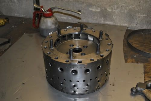 Here is the combustor, bearing tunnel and compressor housing fitted together. 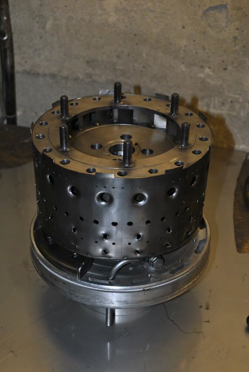 Different angle so you can see the clearance to the oil lines and air deflectors. 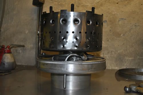 A last picture on the engine with the turbine housing and jet pipe fitted, it looks pretty sweet.  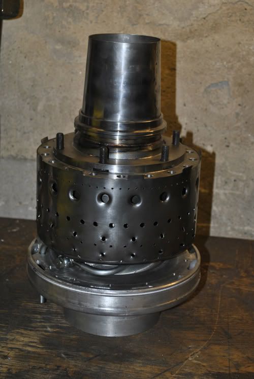 |
|
fricke
New Member
 Jack of many trades....
Joined: August 2010
Posts: 6
|
Post by fricke on Apr 6, 2011 16:44:37 GMT -5
Nice work Anders!!!
|
|
|
|
Post by racket on Apr 6, 2011 16:55:22 GMT -5
Hi Anders
Now thats starting to look like an engine :-)
You should be firing her up by mid summer, if not before hand .
Cheers
John
|
|
|
|
Post by Richard OConnell on Apr 7, 2011 0:37:40 GMT -5
Looks really nice.. I think we need to start some sort of a counter that works like a timeclock on the site that keeps track of your total time on this project  |
|
|
|
Post by Johansson on Apr 7, 2011 1:16:39 GMT -5
Thanks Fricke! It sure starts to look like a gas turbine now.  There is not that much work left before it is ready to fire up; a fuel manifold, impingement air nozzle, propane nozzles, glow plug, coating on the hot parts, an engine stand and the auxillary equipment. I will still take my time with it and make sure to double check every clearance to avoid any stupid mistakes, but it shouldn´t take too long I figure. |
|
|
|
Post by Johansson on Apr 8, 2011 15:25:31 GMT -5
Looks really nice.. I think we need to start some sort of a counter that works like a timeclock on the site that keeps track of your total time on this project  Nemas problemas, I have counted them all and so far I have spent 182 active hours in the workshop on the engine.  |
|
|
|
Post by Johansson on Apr 13, 2011 16:46:26 GMT -5
|
|
|
|
Post by racket on Apr 13, 2011 19:48:17 GMT -5
Hi Anders
Nice work :-)
It will probably be a good idea to lockwire the screws holding the FT in place , they're small enough to go thru a FT wall hole if they come loose from the expanding and contracting , also best if the screws are a dissimilar material to the ears to stop them seizing , I've used "black" high tensile socket heads into my stainless steel hot bits along with high temp antiseize , no problems to date with disassembly .
Looking good :-)
Cheers
John
|
|
|
|
Post by Johansson on Apr 13, 2011 23:58:15 GMT -5
Thanks! The screws on the pic is just for test fitting, I will use 12.9 M5 insex drilled for lockwire later.  Don´t want one of those passing through the turbine...  |
|
|
|
Post by Johansson on Apr 14, 2011 12:16:30 GMT -5
I am planning the fuel manifold build at the moment and one critical moment is silver soldering the thin syringe tubes to the copper manifold. Do you John (or anyone else for that matter, I just know that John has built one before) have any experience with gluing the syringes instead of soldering them to the copper ring? Every copper-to-copper joint will be tig welded since I despise soldering and think it is as stone age as riveting.  The reason why I think it would work is because of the thick NGV front wall that is between the manifold and the heat, the wall will also be coated with cheramics which will lower the heat transfer even more. The manifold will be filled with fuel all the time and relatively cool air from the compressor will surround it, so I cannot see any reason why epoxy or a similar glue would fail in this application. |
|
|
|
Post by racket on Apr 14, 2011 17:18:06 GMT -5
Hi Anders
I've seen your TIG work , its beautiful , so you'll have no problems silver soldering the syringe needles into the fuel manifold , just make sure you use a high silver content silver solder of >45% silver , it'll take to the stainless syringes beautifully ,LOL........ should stick to the copper as well ;-))
..................why are you using copper pipe for the manifold , rather than steel ??
A small propane torch is all you need , just position the syringe needle in the hole , pack a good bit of silver solder flux around the needle and start heating , the flux will go molten and still stay around the needle base protecting it from overheating and going "black" , just melt the tip of the silver solder and add a small drip to the flux , it'll generally go where it needs to ..............its easy :-) .................much easier than when I had to silver solder one syringe needle inside another to reduce the flow in my FM-1 engine , now that was a bugger of a job :-(
I wouldn't trust an epoxy in the high heat environment , too many unknowns
Cheers
John
|
|