|
|
Post by madpatty on Dec 7, 2014 17:11:14 GMT -5
Hi Chris,
Thanks for lifting up my spirits......actually in either case i have to redesign my bearing housing because of the repeated abuse given to the old housing, the turbine side journal bearing seat had gone damaged somewhat......
Moreover i have started to work building an annular combustor around the time tested OEM bearing housing with a much larger gravity drain sump and exact clearances....
Cheers,
Patty
|
|
|
|
Post by madpatty on Dec 10, 2014 7:31:28 GMT -5
Hi Guys, The redesign of the engine has started....using the OEM turbocharger core.....annular combustor will be built around it....won't take much time.... Here are few of the pics:- 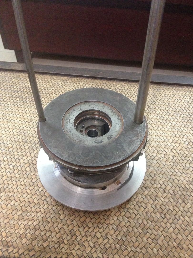 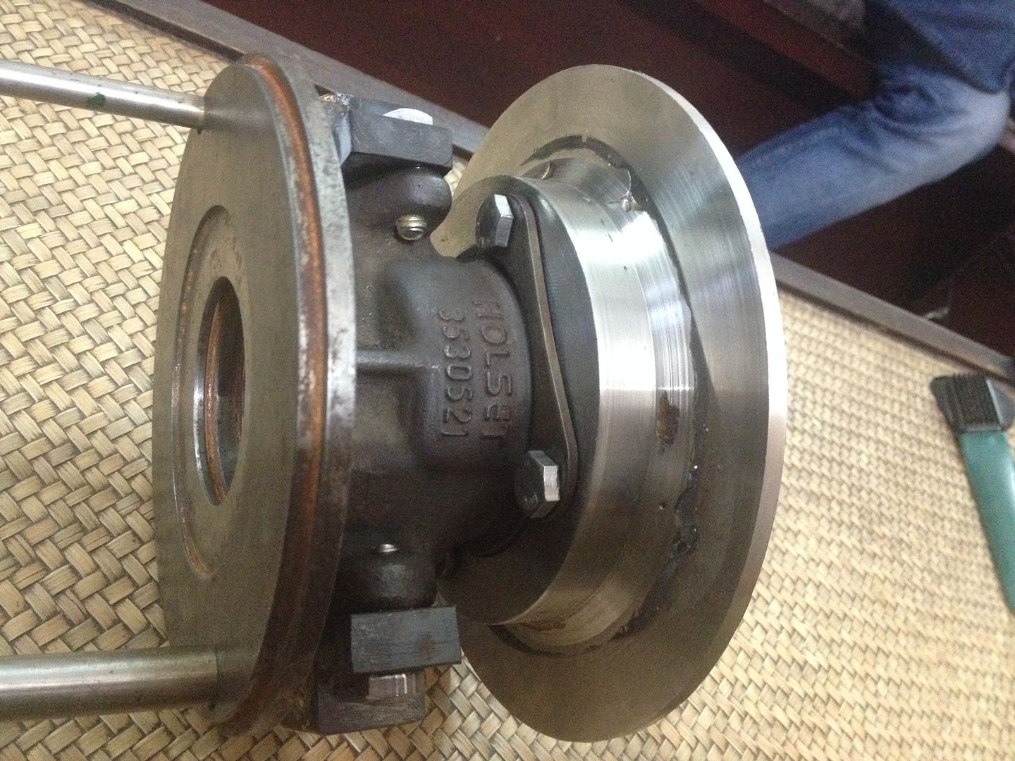 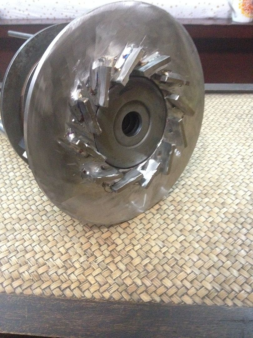 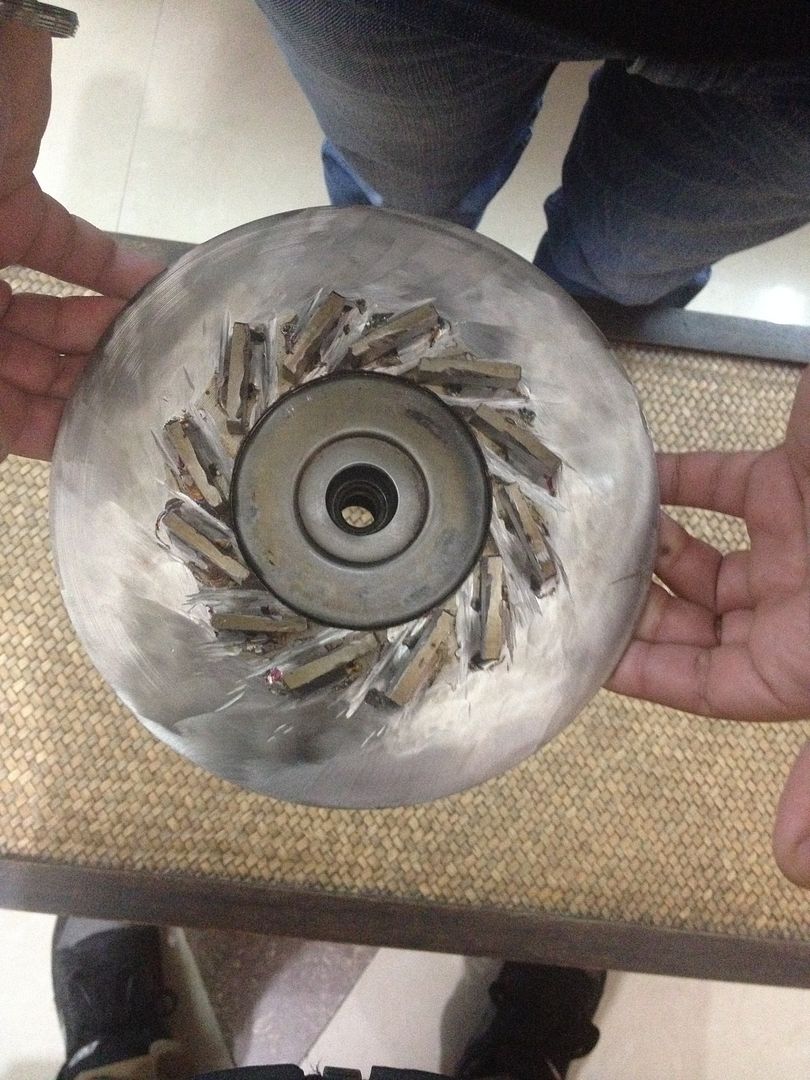 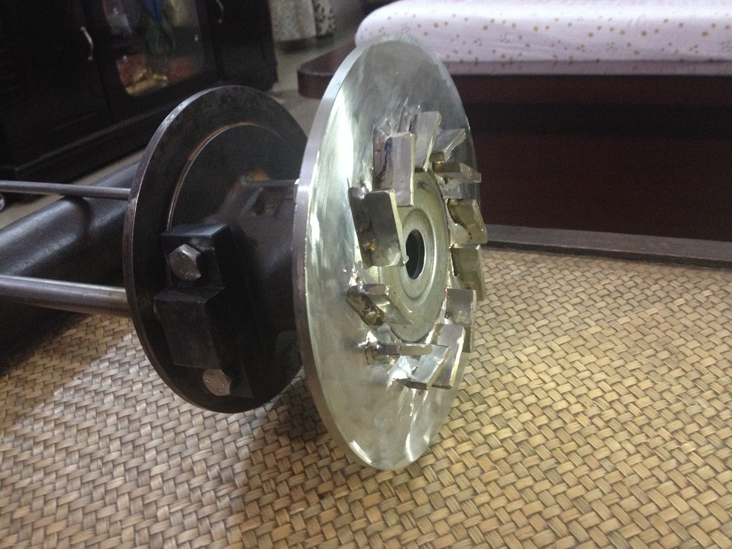 Cheers, Patty |
|
|
|
Post by Johansson on Dec 10, 2014 11:55:58 GMT -5
Why won´t you spend some extra time to get those flat edges on the NGV grinded down? If you build this engine similar to the old one you will get similar results as well...
|
|
nersut
Veteran Member
  
Joined: September 2012
Posts: 223
|
Post by nersut on Dec 10, 2014 12:47:36 GMT -5
Hi Patty Looking at your new NGV pattern, it looks like you will have some problems... The vane distance seems too big, the are areas were gas flow will hit the turbine wheel without being guided to the tips & instead hit the hub 90+ degrees. And the are a lot of variations as you can see below.  If you look at the second picture here below, you can see the gas path will hit the next vane instead of the turbine wheel/tip.  I think that you should rethink/redesign your NGV pattern before you move on. And as Anders says, you should grind/smooth the vanes to a get better gas flow/efficiency. Cheers Erik |
|
nersut
Veteran Member
  
Joined: September 2012
Posts: 223
|
Post by nersut on Dec 10, 2014 13:05:26 GMT -5
Hi Patty I forgot to mention this: As I see it, your turbine wheel got 12 blades & your NGV also got 12 vanes. The number of vanes & turbine blades should never be the same... Unless you are designing a loud air raid siren! = wasting power!  Cheers Erik |
|
|
|
Post by Johansson on Dec 10, 2014 14:16:08 GMT -5
Erik got it right. You should stop rushing ahead and do the math and a good set of drawings first. When you are satisfied with the drawings and the numbers add up you can start building the engine.
Just throwing a half assed engine together in a couple of days and then spend months toasting turbine wheels while trying to figure out why the engine won´t run doesen´t sound like a very clever approach if you ask me.
|
|
nersut
Veteran Member
  
Joined: September 2012
Posts: 223
|
Post by nersut on Dec 10, 2014 20:45:33 GMT -5
I have tried to illustrate the gas flow area here. The first picture below is a NGV from a commercial turbocharger where the inflow area is narrow (yellow) & the steepest angle (red arrow) is more or less tangential to the turbine tips.  As you can see, your NGV design has a very wide inflow area (yellow), the acceleration of the hot gases would be low & create a lot of turbulence. If you look at the steepest angle (red arrow) you will notice that it is not tangential to the turbine tip area but is pointing toward the hub. Cheers Erik |
|
|
|
Post by madpatty on Dec 12, 2014 7:38:31 GMT -5
Hi Erik, Those vanes are designed according to the throat area......what do you think:- Will elongating the NGV vanes(or welding another vane just behind those NGV vanes) help in reducing that steep inflow angle?? Just a pic for illustration:- 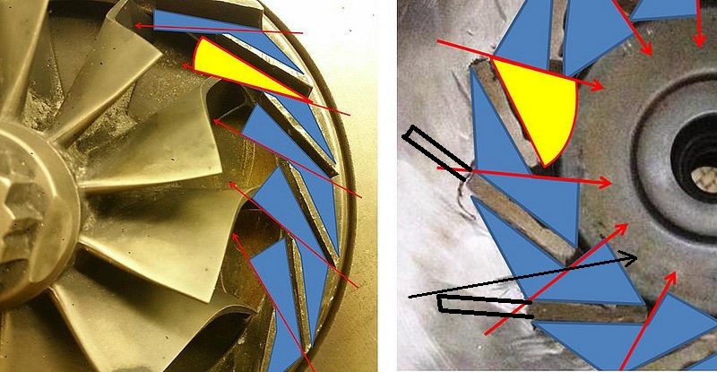 cheers, Patty |
|
nersut
Veteran Member
  
Joined: September 2012
Posts: 223
|
Post by nersut on Dec 12, 2014 9:47:10 GMT -5
Hi Patty Ok, you also have to "visualize" the gas flow, in your mind...  If you don't have access to fluid dynamics software. Your slots/vanes have very poor aerodynamic design with sharp 90 degree edges, this will create a lot of resistance, drag & turbulence when high speed gas flow around then.  If you look at the picture above you can see the yellow area at the front of the vane, gases from the combustion with gas high speeds will hit this flat spot on the leading edge of the vane, this will disrupt the gas flow creating resistance, drag & turbulence = Loss in efficiency = stealing power. Secondly, you can see at the trailing edge of the vane, the yellow area shows a low pressure area with lot of turbulence, because of the 90 degree edges & a wide inflow area = Loss in efficiency = stealing power. Now if you add some length to the vanes, green area below, your inflow area will get narrower. BUT you still have to remove those sharp 90 degree edges from the vanes. If you cut/grind the yellow areas like on the picture below the gas flow will better = More power to the turbine wheel.  BUT if you grind metal of the trailing edge your will alter the throat area, the throat area will get larger. So, my suggestion is: Start over with the NGV design.  Make calculations, paper templates, "visualize" the gas flow & if you are satisfied will your design, then start cutting the vanes & this is important! Grind those vanes to get a good aerodynamic profile, not the other way around.  The nice & smooth gas flow is very important throughout the engine, from air inlet to exhaust nozzle. If you skip some areas it will act as a bottleneck & it WILL alter the whole engine in a bad way. Cheers Erik |
|
|
|
Post by madpatty on Dec 12, 2014 10:17:25 GMT -5
Hi Erik,
OK done......
Cheers,
Patty
I was planning to drill holes in the flametube.....earlier i used 3 mm holes for primary zone, 5 mm for secondary and 9 mm for tertiary.....
Are 3mm holes enough to provide enough air penetration in primary zone or should i enlarge them to say 4 mm.....if anybody can enlighten me on this....:-)
|
|
nersut
Veteran Member
  
Joined: September 2012
Posts: 223
|
Post by nersut on Dec 12, 2014 11:13:38 GMT -5
Hi Patty Are you going to build the combustor around the turbocharger center housing? If so I will assume that it will get pretty big radially or "fat" and short. The short distance between the compressor & turbine will limit the combustor length. If the combustor is too short you can get troubles with too high TIT/TOT. Maybe you could try another method. A reverse flow annular combustor (with radial outlet). This way the combustors length is not limited by the turbocharger shaft length, which could be an advantage to TIT/TOT temp. control.  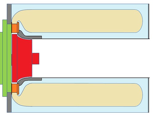 Cheers Erik |
|
|
|
Post by madpatty on Dec 12, 2014 11:37:40 GMT -5
Hi Erik,
Actually it is a bit strange but with this new design the main body of the combustor turned out to be 75mm in length.....that is larger than my previous design where it was only 55mm.......
moreover i read it somewhere that Ander's and Racket's engines also have this much length of their combustor main body.....
And when taking into account the mass flow they have, i think this length will be more than enough for my combustor....
Moreover GR180 design which is very commomn on net also has only 77mm of combustor main body....
Cheers,
Patty
|
|
nersut
Veteran Member
  
Joined: September 2012
Posts: 223
|
Post by nersut on Dec 12, 2014 13:53:09 GMT -5
Hi Erik, Actually it is a bit strange but with this new design the main body of the combustor turned out to be 75mm in length.....that is larger than my previous design where it was only 55mm....... moreover i read it somewhere that Ander's and Racket's engines also have this much length of their combustor main body..... And when taking into account the mass flow they have, i think this length will be more than enough for my combustor.... Moreover GR180 design which is very commomn on net also has only 77mm of combustor main body.... Cheers, Patty Hi Patty Ok, 75 mm is maybe not an issue if you can build a very good combustor. To evaporate & burn all the fuel, convert all that energy in such a short distance to a acceptable temperature before entering the NGV/turbine need a very good design. John & Anders has expert knowledge of designing good combustors. I am just giving you some advice, which could be useful sometimes.    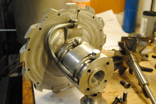  If you look at the turbocharger center housing you are using, it is "a lot" bigger that a John's, Anders's & the GR180. Your oil return line with 90 degree turn & relative small diameter tube could also be a problem, causing poor drainage, oil leaks & bearing failure. We learn by trial & error... But if we can minimize the "error" part by not ignoring some problem areas we already know, we learn faster!  But of course, you are the designer & builder, so go ahead! Have a nice weekend! Erik |
|
|
|
Post by madpatty on Dec 12, 2014 23:30:37 GMT -5
Hi Guys,
So i am currently redesigning the NGVs.....
The things to be taken care of:-
1. NGV number should not be equal to turbine blade count......so i am going with 15 NGV vanes....
2. The leading and trailing edge should be made aerodynamically correct....
One thing that is concerning me now is while designing the 15 vane NGV, the absolute angle of NGV's came out to be 35 degrees to the tangent to get the required throat area.....this is due to the thickness of NGV's i am currently using which is 5mm because of the availability issues of ss316 here......minimum thickness sheet available here is 5mm only......
So i had two queries if anyone can answer:-
1. Is that 35degrees to tangent angle good to go(to get required throat area)??
2. Can ss304 be used for NGV's??if so them what minimum thickness required??
I am more inclined in using ss316 dur to its better heat resistance.....
Cheers,
Patty
|
|
nersut
Veteran Member
  
Joined: September 2012
Posts: 223
|
Post by nersut on Dec 13, 2014 0:11:48 GMT -5
Hi Guys, So i am currently redesigning the NGVs..... The things to be taken care of:- 1. NGV number should not be equal to turbine blade count......so i am going with 15 NGV vanes.... 2. The leading and trailing edge should be made aerodynamically correct.... One thing that is concerning me now is while designing the 15 vane NGV, the absolute angle of NGV's came out to be 35 degrees to the tangent to get the required throat area.....this is due to the thickness of NGV's i am currently using which is 5mm because of the availability issues of ss316 here......minimum thickness sheet available here is 5mm only...... So i had two queries if anyone can answer:- 1. Is that 35degrees to tangent angle good to go(to get required throat area)?? 2. Can ss304 be used for NGV's??if so them what minimum thickness required?? I am more inclined in using ss316 dur to its better heat resistance..... Cheers, Patty Hi Patty That sounds good  SS304 should be ok, actually the melting point of SS304 is a little higher (1400-1450 °C) than SS316 which has a melting point of 1375-1400 °C. Link
The difference between SS304 & SS316 is, SS316 is added with 2-3 % Molybdenum and SS304 has no Molybdenum. The Molybdenum is added to help resist corrosion to chlorides (like sea water). The maximum oxidation service temperatures for heat resistance for SS304 & SS316 is the same, 870 °C linkCheers Erik |
|