|
|
Post by madpatty on Dec 13, 2014 0:40:27 GMT -5
Hi Erik,
That sounds good too.....;-)
Actually that way i can use thinner NGV's......as thinner sheets are available for ss304..
Cheers,
Patty
|
|
|
|
Post by finiteparts on Dec 13, 2014 0:59:56 GMT -5
Hi Patty,
Just a quick comment on NGV design.
Selecting the discharge angle for the NGVs should be based on the turbine inlet vector diagram generated at the design point conditions. Once you have the vectors, you then can adjust the vane count or the vane thickness to control the throat area.
Trying to pick the discharge angle for the NGVs based on the required throat area is an incorrect method.
I will work out an example for you and post it up some time tomorrow, so that hopefully, seeing an example will help it become more clear and get you a properly designed NGV section.
- Chris
|
|
|
|
Post by madpatty on Dec 21, 2014 12:22:35 GMT -5
Hi Guys, Had been working on the diffuser and NGV design of the engine lately..... i had sourced some thin ss304 strips for NGV and ground their edges to make them aerodynamically correct as recommended by Chris and Erik. Here are few of the pics:- 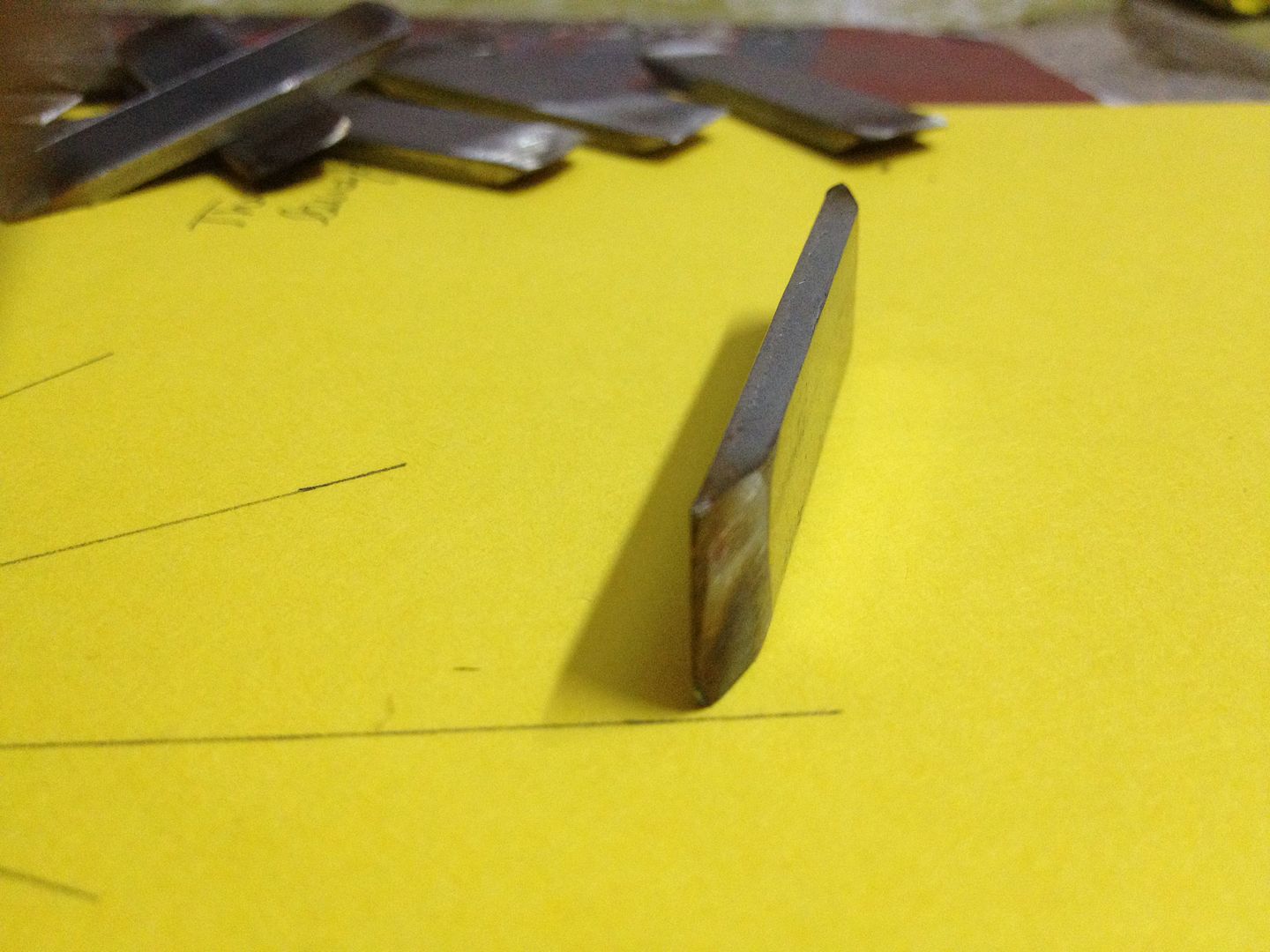 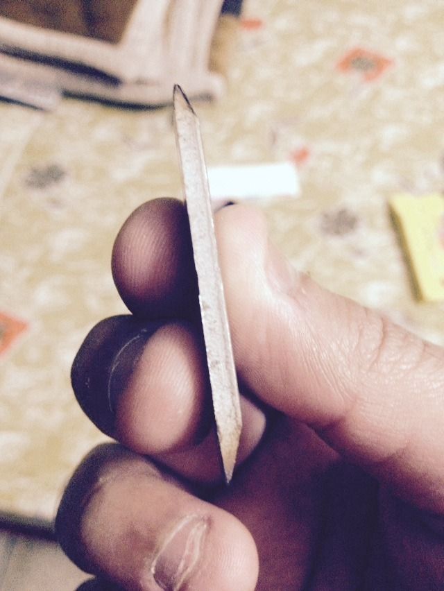 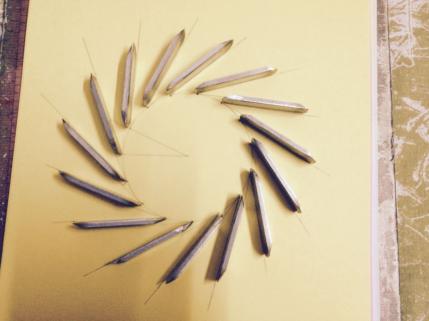 image is just for reference....i will be redesigning the NGVs according to throat area and angle suggested by Chris.....but one think that is sure is the new NGV count will be greater than that in the above pic.... Moreover the NGV number has also been changed as pointed out by Erik that same number NGVs as turbine blades will cause vibrations...... cheers, Patty |
|
|
|
Post by madpatty on Dec 21, 2014 12:33:50 GMT -5
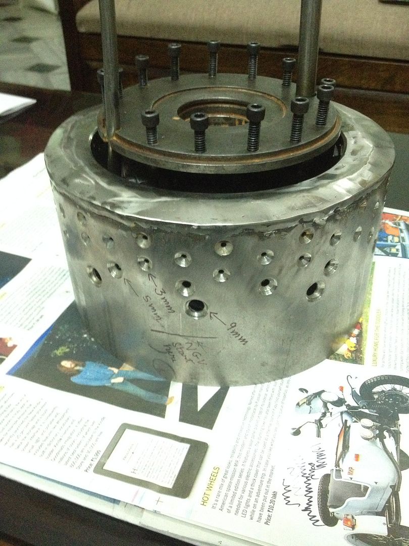
i had some doubts in the combustion chamber design..... The main body of the combustor is about 70mm(not 77mm)...... 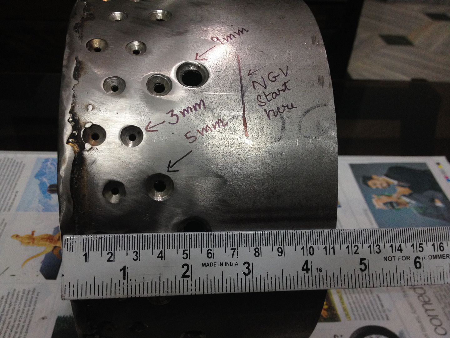 In the primary zone there are total 96 holes of 3mm dia......(48/3 in first three rows of outer can and 48/2 in first two rows of inner can)...... In secondary zone ther are total 24 holes of 5mm dia.....(16 in fourth row of outer can and 8 in third row of inner can)...... In tertiary zone there are 18 holes of 9mm dia....(10 in last row of outer can and 8 in last row of inner can)..... One thing that is disturbing me now is the axial position of the tertiary holes.....they appear a bit closer to secondary ones....won't they interfere with combustion??if anybody can share a thought..... I had marked the starting point of NGVs on the outer can for reference so as to get the position of tertiary holes with respect to it..... 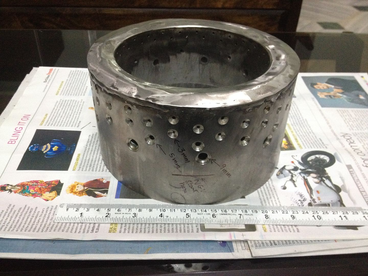 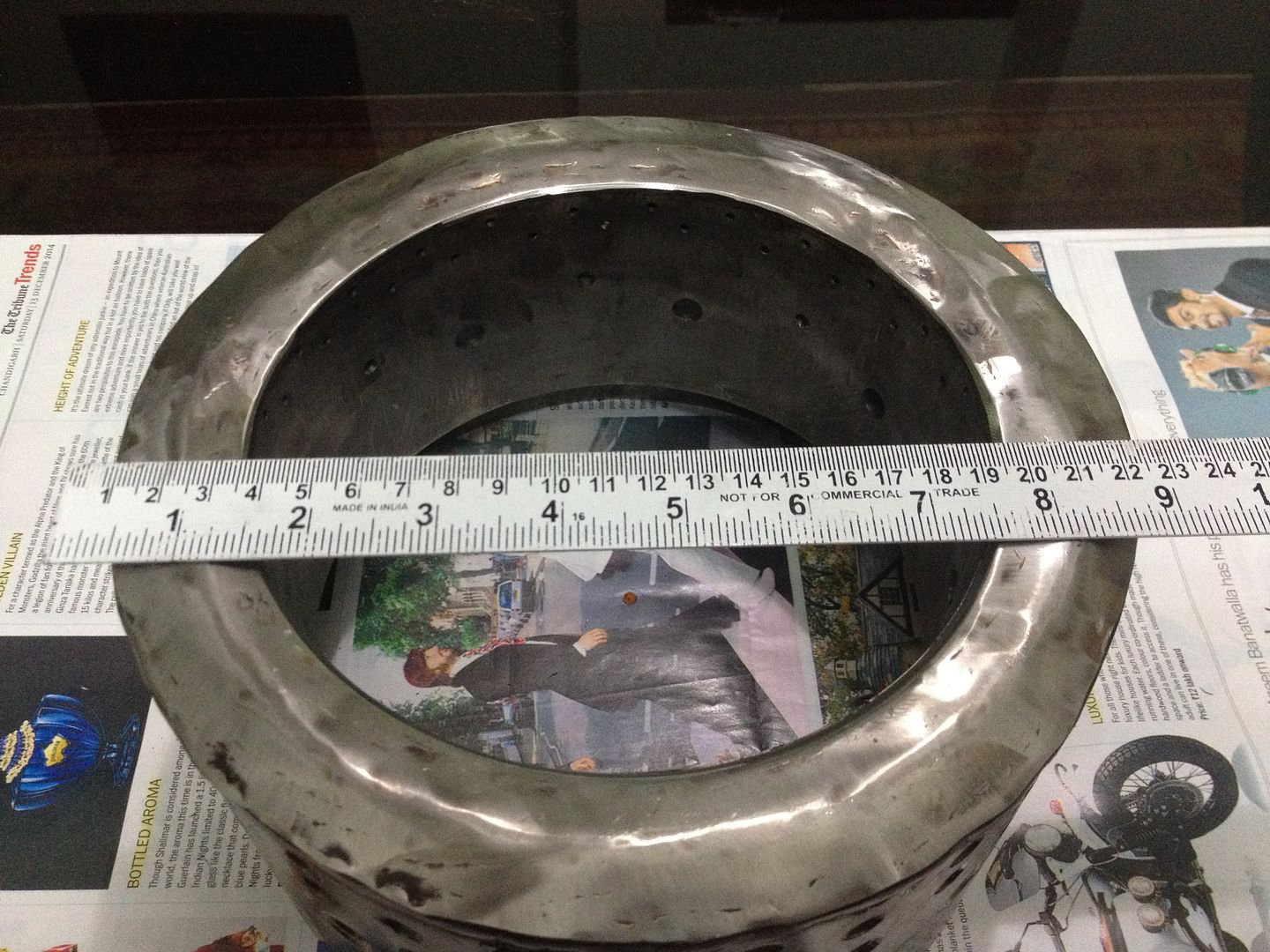 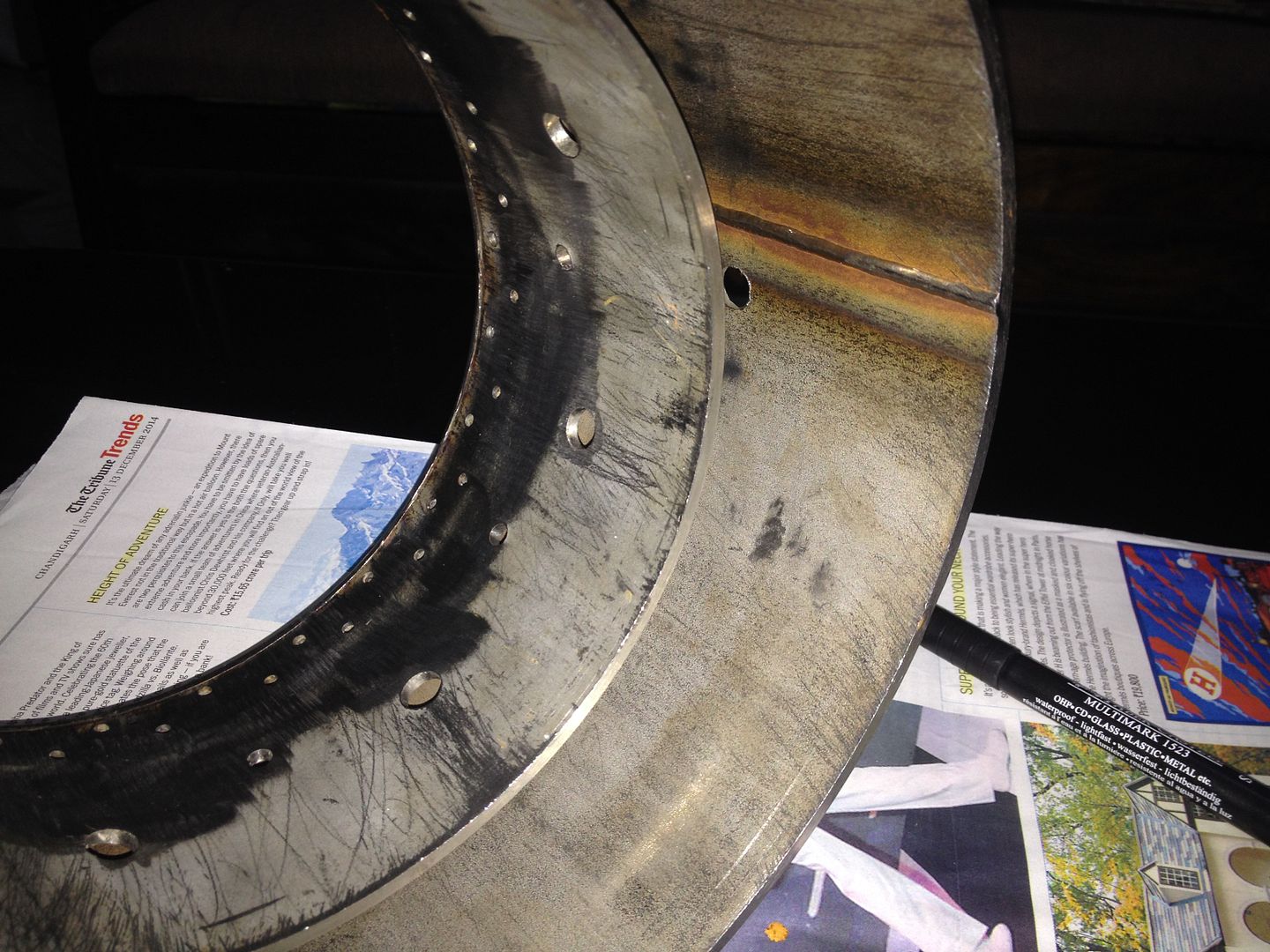
 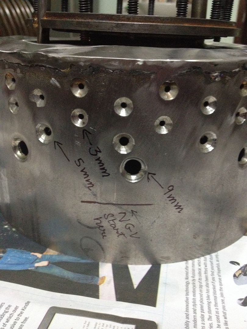  cheers, Patty |
|
|
|
Post by madpatty on Dec 21, 2014 12:42:37 GMT -5
Now coming to the diffuser design...... I had to design something that could fit the OEM core so i thought of designing the inverted diffuser attached to the compressor cover rather than the ordinary widespread design....that saved me some more space for CC axially...... Made a seat for the compressor plate in the diffuser so that diffuser can then be screwed to the compressor plate..... 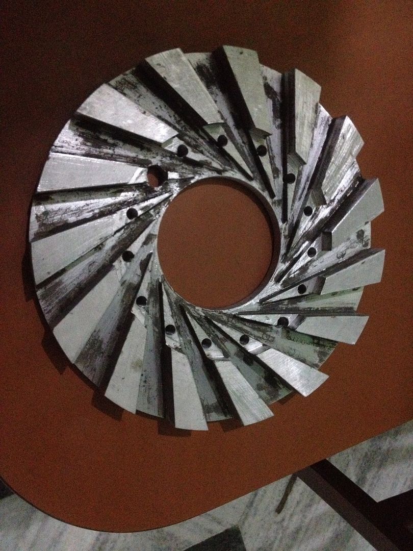 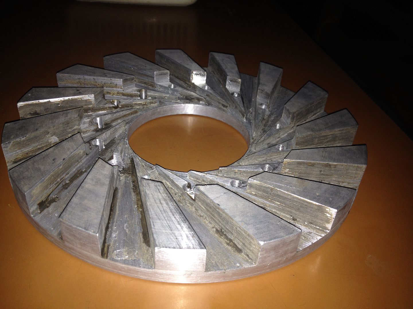 The diffuser blades here are machined down to match the size of compressor exducer tips... 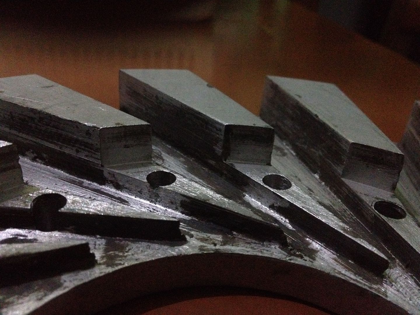 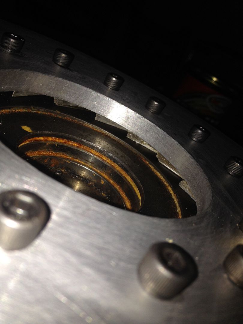 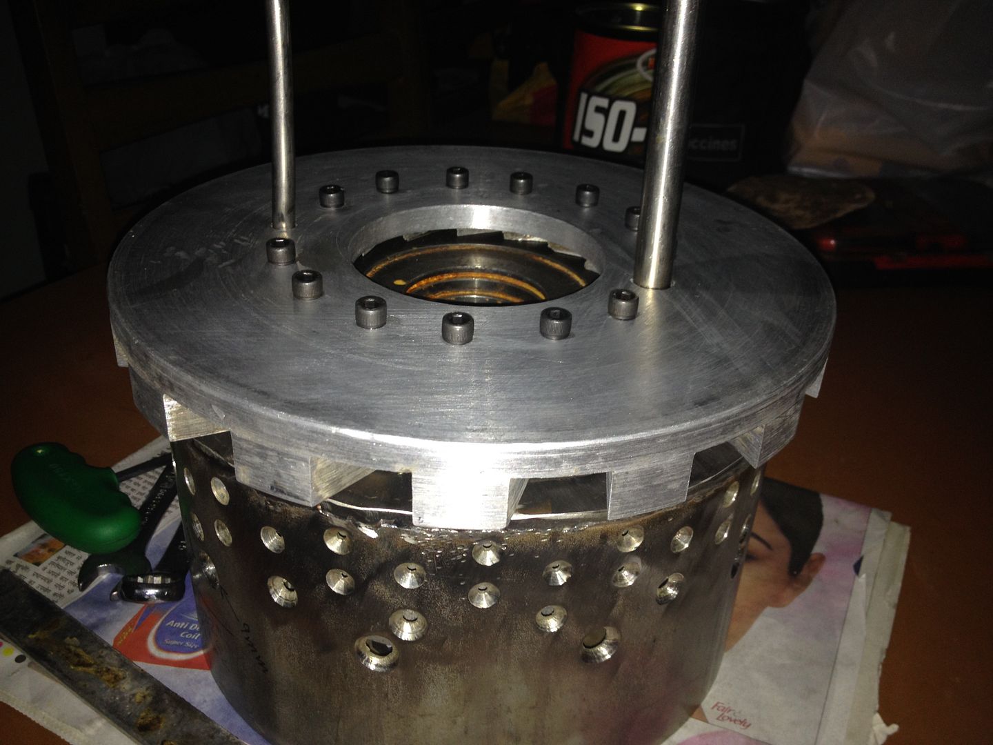 The next job now is to round the exit of the diffuser for smooth turning of air flow.... cheers, Patty |
|
|
|
Post by finiteparts on Dec 22, 2014 2:01:29 GMT -5
Hi Patty,
That is one short combustor you have there! In order to get the combustor intensity needed and be able to burn in such a short length, you are going to need a bunch of vaporizers. You really need to break up the combustion into small amounts to get the mixing way up. Think of it as putting sugar in your coffee or tea. If it is large grains, it takes a while to dissolve, but if you get the grains smaller (thus increasing the total surface area between the sugar and the liquid) it dissolves quicker. A smaller amount of fuel in each vaporizer tube will increase it's vaporization rate by increasing the vaporizing surface to fluid volume ratio and allow you to vaporize it in such a short span. You need vaporizers and fuel flows on the order of what is used in r/c turbines to complete combustion in such a short length.
It is going to be a challenge for you to get complete combustion before you hit the NGVs.
Good luck!
Chris
|
|
|
|
Post by madpatty on Dec 22, 2014 2:11:39 GMT -5
Hi Chris,
I will fit in more number of evaporators then because i have got a good bit of circumference there....maybe 18 evaporators at 20degree each......
Cheers,
Patty
|
|
|
|
Post by finiteparts on Dec 22, 2014 12:21:31 GMT -5
Hi Patty, I measured the fuel injector tubing size going into the vaporizers on one of my r/c engines and it is 0.047 inch brass tubing....I am assuming that it is likely similar to what you can buy from KS Metals, so that puts it at around 0.035 inch inside diameter. www.ksmetals.com/resources/cuttolength.pdfI would guess that diameter should be close to your upper limit of what you should use for each vaporizer...more fuel and you might not vaporize fast enough to complete the combustion prior to the vaporized liquid (hopefully) entering the turbine section. Vaporization rate of liquid droplets goes up as the square of the diameter, so larger droplets take substantially longer to vaporize prior to combustion. Now, when you go to a liquid sheet that becomes even more complicated to calculate...but you know that you want to maximize the contact time with the heated walls of the vaporizer tubes...so with small tubes and maximized the length of the vaporizers will give you the best chance. The r/c combustor has a length of 2.75 inches, so it is possible to get complete burning in the short length that you have...  The vaporizer tubes are 0.25 inch outer diameter and the id is 0.185 inch. If I was to trying to calculate the required number of vaporizers, I would take the required volumetric flow rate of fuel at full power and then assume a fluid speed out of each injector tube that would "keep" it in the vaporizer long enough to "boil" off. Maybe trying to balance the enthalpy of vaporization of the fuel and the heat release rate of the air-fuel mixture (with a percentage that can be transferred through the vaporizer tube wall)...maybe... The shear rate at the fluid and gas interface might be a good way to breakup some other flow. Now, before you ask me how to do that, I will tell you that I haven't even tried to work that out. What you could do, is take the fuel flow for a RAM 750 at full power and divide that by 6 tubes to get a rough idea. Good luck! Chris |
|
|
|
Post by Johansson on Dec 22, 2014 13:22:01 GMT -5
I get a little confused looking at the pic of the stepped diffusor vanes, is there a smooth passage for the air coming from the compressor exducer all the way to the diffusor exit?
Judging from the pics there is a sudden huge area increase and that would produce all kinds of flow disturbances.
The combustor material is another issue, it looks very thick to me. A thin sheet metal combustor can be made a bit larger and I thing you will need all the combustor volume you can get.
/Anders
|
|
miuge
Veteran Member
  
Joined: March 2014
Posts: 200 
|
Post by miuge on Dec 22, 2014 16:39:49 GMT -5
Inverted diffuser looks a bit strange.. With that compressor back plate air has a quite difficult path to inner can. Will there go any? Also it will disturb the flow to outer can.
|
|
|
|
Post by finiteparts on Dec 22, 2014 18:13:17 GMT -5
Hi Patty, I think you should terminate your diffuser "vanes" at the edge of the back plate and essentially create a large discharge plenum. Machine all that outer stuff away. There will be dump losses, but you can try to modify the exit of the diffuser vanes like the r/c engines do, see the images below.   If you have a relatively large discharge plenum, you might get better feeding of the inner combustor holes, that will be an issue otherwise. You might want to clean up the back plate also, since that little step where it used to meet up with the front housing does not help anything, just trips the flow. Since you don't have any deswirling vanes, your discharge will have some swirl in it, that might help the air get down into the center by having a bulk swirl motion (as long as the swirl isn't too high, because that would keep the bulk flow out on the outer wall). Looking at your oil drain, I think you are going to still have trouble. The size is too small and the horizontal discharge is not good. If you look at the Holset install specs for the HX35, they state, "11. Oil return pipes are permitted to decline at an overall angle of not less than 30 degrees below horizontal. All turbocharger applications require a pipe of internal diameter greater than 19 mm which has integrated connectors. To ensure oil drains into the engine under all operating conditions, the return connection into the engine sump must not be submerged and the outlet flange of the turbocharger must be 50 mm above the maximum oil level of the engine sump pan. " The only way you might get away with that horizontal oil drain is to install a scavenging pump to pull the aerated oil out of the bearing housing. Good luck! Chris |
|
|
|
Post by madpatty on Dec 22, 2014 19:03:33 GMT -5
Hi Chris,
I didn understand when you say..
"You might want to clean up the back plate also, since that little step where it used to meet up with the front housing does not help anything, just trips the flow"....
Actually that step is made for this purpose so as to immitate the deswirling vanes because they are extending below that compressor discharge plate....it is similar to what everbody does here but in opposite way....i think it's just like larger de swirling vanes.......
Regarding the supply to inner holes...the compressor discharge plate ends before the start of inner can.....moreover axially also there is a gap of about 10mm between compressor discharge plate and inner can.....wouldn't it be relatively easy for the air to go towards the inner can rather than turning full 180degrees to reach the inner can in what occurs in notmal design......
I will be using an external gear pump as scavenge pump...
Cheers,
Patty
|
|
nersut
Veteran Member
  
Joined: September 2012
Posts: 223
|
Post by nersut on Dec 23, 2014 11:39:16 GMT -5
Hi Patty As Anders mentioned earlier, it seems you are going to have a problem with the sharp 90 degree step in the diffuser vanes. If you look at the cross section sketch below, you can see an area with a lot of turbulence.  Cheers Erik |
|
|
|
Post by madpatty on Dec 23, 2014 12:05:46 GMT -5
Hi Erik, i understand that point completely.....but according to the diameter of the compressor plate and where that region of larger area starts isn't the velocity of the flow already decreased much by then....as you can see RC jets of flow comparable to mine engine had got much much smaller diameter diffusers..... moreover it appears from your drawing that air knows only one path to follow which is radially outwards but in my case there is an empty space downwards also towards the combustion chamber.....i am posting an image of rear face of the diffuser with compressor place attached..... 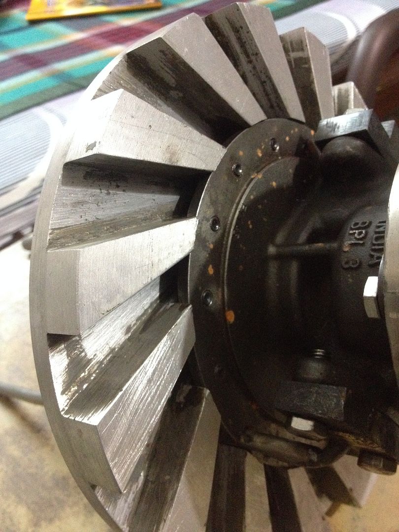 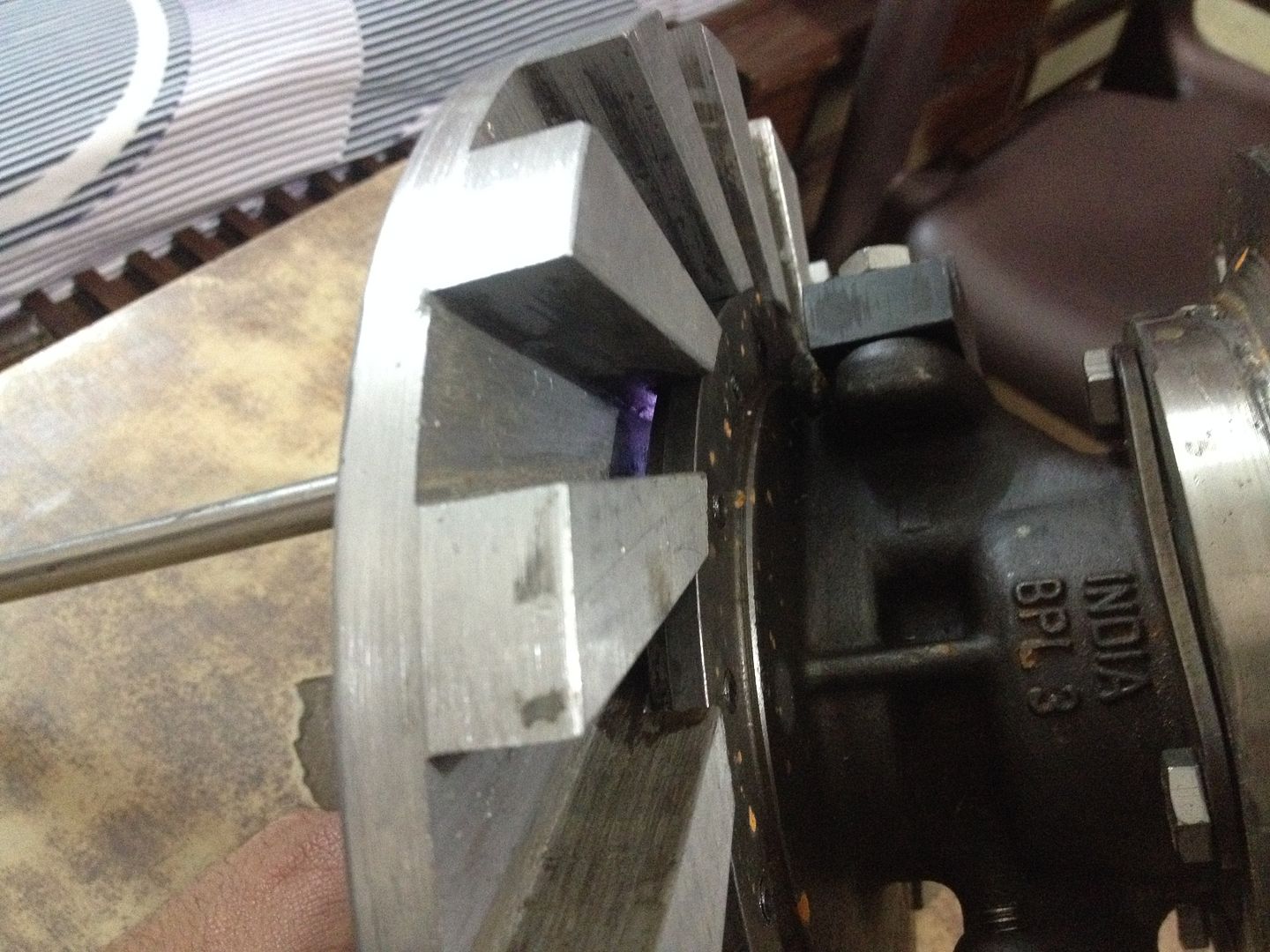 cheers, Patty |
|
|
|
Post by Johansson on Dec 26, 2014 10:28:43 GMT -5
So you are going to use an unshrouded diffusor??
If you really want to make this engine a runner then stick to a common design, the diffusor wont work without a cover and losses will be much increased compared to a standard one.
|
|