|
|
Post by Richard OConnell on Jun 9, 2015 14:33:43 GMT -5
Are you dumping fuel into the AB and igniting it without using a flame holder to create a low pressure area for the flame to roll behind?  In the image above, a ring is placed in the afterburner to protect a small zone from being extinguished by the high velocity airflow.http://jetandturbineowners.proboards.com/post/12819/edit# EDIT: A second image  EDIT2: Just going to leave this here  engineering.purdue.edu/AAE/Academics/Courses/aae537/2009/Afterburner%20Review engineering.purdue.edu/AAE/Academics/Courses/aae537/2009/Afterburner%20Review |
|
|
|
Post by madpatty on Jun 9, 2015 20:03:46 GMT -5
Hi Admin,
Thanks for sharing the information. I am using a dump style afterburner without any flameholders.
BUT HEY, i think you have misinterpreted my post.
I am not concerned about the afterburner this time but running the gas producer on liquid fuel.
The problem is i have to run my engine on gaseous fuel which i want to shift to liquid fuel.
(Afterburner is already on diesel)
But with liquid fuel i am afraid i will again fry my NGVs as temperatures remain higher near the NGVs with liquid fuel.
Cheers,
Patty
|
|
|
|
Post by finiteparts on Jun 9, 2015 20:28:50 GMT -5
Hi Patty,
How are you controlling the amount of liquid fuel to the engine? Could you have just pushed in too much fuel when you had trouble in the past?
It seems like you should be able to slow transition over from the gas to the liquid fuel without any issue...assuming you are running two separate fueling circuits. Slowly bring in the liquid fuel while reducing the gas fuels flow rate.
~ Chris
|
|
|
|
Post by madpatty on Jun 9, 2015 20:48:14 GMT -5
Hi Chris,
The amount of fuel was controlled using a PWM circuit controlling the fuel pump.
But i think i had done max. Slowly possible but temperatures still rise.
Till 15 Psi P2 its sort of OK (turbine not glowing at all) but after that everything starts to glow. The maximum hot region are the NGVs..
Cheers,
Patty
|
|
|
|
Post by racket on Jun 9, 2015 21:41:26 GMT -5
Hi Patty
The problem is your flametube design , looking back at your pics it appears to be ~1 inch radial width whilst ~7" mean diameter , 7" mean gives ~22 inches circumference , but with only 12 evaporators their discharges won't be overlapping , you need at least twice as many evaporators in such a thin annular flametube .
Your evaporators will need to be as thin walled as possible , preferably 0.5mm WT .
The fuel must be injected onto the inner wall of the evap .
Cheers
John
|
|
|
|
Post by madpatty on Jun 9, 2015 22:07:37 GMT -5
Hi Racket,
I am using 16 evaporators and they are 1 mm thick....they are the thinnest i can buy here....
But the flametube cross section is more than 3 times inducer area.
It appears as if evaporators are not working properly.
I have already D'd the evpaorators along there length.
What else can be done?
Cheers,
Patty
|
|
|
|
Post by racket on Jun 10, 2015 0:17:52 GMT -5
Hi Patty
Do you have a pic of your "new" evaporators as mounted in the flametube , its very difficult to provide a solution when we're working with out of date pics.
A few details required about your 16 evaps ,..........
What bore size ??
How long??
What is the distance between evap outlet and front wall of flametube ?
Do you have any wall holes that blow through the "mixture" exiting the evaporator ??
Is there any provision for swirl(rotary) production with your wall holes ??
Cheers
John
|
|
|
|
Post by madpatty on Jun 13, 2015 0:38:12 GMT -5
Hi Guys,
Has anybody got any data on:-
What is the power consumption vs pressure(and flow) of various pumps.?
I am using a hydraulic pump(gear pump) but thats very power hungry.
It sometimes overloads my 1 hp motor just pumping oil at 60Psi......
i am totally confused how gear pumps(working on same principle) from ebay and same as What Anders is using is able to pump that much oil at that pressure 4-5 bar with such a small motor of max power rating 150 watts.
Is there a difference between hydraulic pumps and these gear pumps.
Also suugest me anybody how good are the GEROTOR and VANE pumps?
I have an easy access to power steering pumps(VANE PUMPS).......has anybody tried those...how much power approx. they need to pump enough oil at about 50-60 Psi pressure.
Cheers,
Patty
|
|
|
|
Post by pitciblackscotland on Jun 13, 2015 1:18:25 GMT -5
Have you thought about using a small IC motor to run your oil pump ? On my first turbo jet engine i use a IC motor to run the power steering pump at low idle no problems, got 60 PSI oil pressure.
Cheers,
Mark.
|
|
|
|
Post by madpatty on Jun 13, 2015 2:21:30 GMT -5
Hi Mark,
I am currently using a 1 hp motor that is almost at its full load....
Are those small IC motors(like those on leaf blowers) capable of that much power?
Cheers,
Patty
|
|
|
|
Post by pitciblackscotland on Jun 13, 2015 5:46:55 GMT -5
Hi Patty,
Yeah a small 2 stroke motor like the leaf blowers. I personally would go for a 2 or 3 HP motor.
Cheers,
Mark.
|
|
enginewhisperer
Senior Member
  
Joined: September 2010
Posts: 494
Member is Online
|
Post by enginewhisperer on Jun 13, 2015 6:17:35 GMT -5
I used a power steering pump run by a 12v 300w scooter motor, with good success. It only needed around 150w of power to maintain decent oil pressure - but I had a regulator on it so it wasn't having to pump massive pressure when the oil was cold.
|
|
|
|
Post by finiteparts on Jun 13, 2015 14:18:36 GMT -5
Patty, That seems like an excessive amount of power required to get to only 60 psi. As for which pump to use, gear, vane, gerotor, etc...it doesn't really matter when you are dealing with constant volume (CV) pumps. Just as the name implies, constant volume pumps will push very close to their rated volume for each rotation irregardless of the downstream pressure. The fact that there are small clearances in the pumps mean that there will be some amount of fluid that slips through those gaps, which depends on the fluids viscosity and the pressure ratio across the pump. For oil, this is a very small fraction of the pumps rated flow as you can see by the flow rate curves in the right plot...(from: www.liquiflo.com/v2/gears.htm) As you can see above representational curves (way oversized for our needs), the pump power is based on the flowrate and pump speed to produce the require pressure drop through the system. The oil system of your engine determines the operating condition of the pump...the flow areas and the losses that the oil will encounter as it passes through your oil system is totally determined by your design and this will control where the pump's operating condition will be on the map. Looking at the above flow curves (which are similar to all constant volume pumps), and the fact that 60 psi is not very high for any CV pump, it should be apparent that your system's flow rate is too high for your pump. There are many reasons why your engine could be flowing to high a flow rate, but I would assume that the controlling orifice would be in your bearing system. If you feel like your bearing system is pretty tight, then the next likely response is that your oil pump is sized too small, such that the controlling orifice area is large relative to the pump's capacity. Do you have a size rating on the pump? You could try to put a smaller orifice in your oil supply very close but upstream of the bearings, similar to what is done in ball bearing turbos, this will help to backpressure the pump at a lower flow rate. Just be carefull to make sure that you are at least getting the minimal recommended flow rate (Holset says 1 L/min at engine idle and 3L/min at max torque). This is not the best option, getting the right size pump is the better way to go. For the Holset HX35, they specify about 0.8 gallons per min (~ 48 gph) at a pressure between 30 - 72 psi. The Procon pump that I am using shows to require only 0.09 hp to flow 50 gph at 50 psi (0.15 hp at 100 psi), which is probably rated with water, so the oil rating will be a bit higher. But 1 hp seems really high. If you know your oil inlet pressure and then assume that the outlet pressure is ambient, you could use Bernoulli's equation to calculate the effective area of you engines oil system. This would then allow you to size the pump for a given power and flow capacity. As for your overheating on liquid fuel, the description of what you are seeing suggests that the combustion is either not getting completed before the tertiary holes or you are over-fueling. If combustion is still occurring as the gas passes the tertiary holes, you don't mix the two streams and thus you don't cool the bulk gas flowing into the NGVs and turbine. So why would the combustion occur late? Like you stated, if the evaporators are not effectively evaporating the liquid, there is extra time needed to evaporate the droplets into a gas phase before they begin to participate in the combustion. If the liquid fuel exits the vaporizer, it takes time to evaporate out, which means that the combustion reaction of that fuel occurs "late" in the combustor. If this droplet evaporation occurs as the droplet is whizzing by the secondary or tertiary air streams, the the headend runs lean and thus cold, which hurts the evaporation process and flame stability. The evaporated fuel then uses the oxygen from the secondary or tertiary air streams/mixing zones to complete the combustion process. Thus there is a reduced cooling effect of the tertiary jets and the bulk gas temperature entering the turbine section is increased. But you could also be flowing too much fuel and thus the primary zone would run rich, causing the late burnout because there isn't enough oxygen till the fuel hits the secondary or tertiary air. Without metering the fuel, how do you know much fuel you are introducing? If you flow too much fuel, you will also compound the problem by having a larger mass of liquid fuel in the evaporator and over cool the evaporator walls, thus limiting the evaporation. If your engine runs ok in a gas only condition, above where this overheating is occurring, then there is a problem with you fuel flow rate and/or evaporator performance. If the evaporator is performing properly, then only a premixed gas-air mixture should be exiting out...this should burn very similarly to the bottled gaseous fuel. The actuality is that the kerosene hydrocarbon chains have broken into more common gases like methane, ethane, butane during the evaporation process. So the burn rate should be similar. To throw another curve into the discussion, you must remember that the energy density of liquid fuel is much larger than the gaseous fuel. The liquid fuel requires very small flow rate changes as compared to the gaseous fuel. This is why I feel like you are over-fueling your engine. Are you running two separate fuel systems, one for gas an one for liquid? Good luck, Chris |
|
|
|
Post by madpatty on Jun 13, 2015 21:22:38 GMT -5
Hi finiteparts, The pump is rated at 8 lpm for the hydraulic oil. But the tests revealed almost 4 lpm at 60 psi with needle valve full open.There is needle valve inline upstream to turbo oil inlet to control the pressure gong into the turbo of the cold oil. The oil circuit is Pump---> T-Joint---->(one part of T-joint exhausted to tank through pressure relief valve)----> other part of T-Joint to turbo through a needle valve.
when in cold conditions i close the needle valve to limit the pressure going into the turbo the exhaust flow is bypassd into tank through a pressure relief valve set at almost 60 psi. So this means my pump is producing all times about 60 psi pressure. when i try to increase the backpressure on the pump by closing the needle valve and also increasing the opening pressure of pressure relief valve then motor takes load and is on the verge of stopping. Cheers, Patty Hi Patty Do you have a pic of your "new" evaporators as mounted in the flametube , its very difficult to provide a solution when we're working with out of date pics. A few details required about your 16 evaps ,.......... What bore size ?? How long?? What is the distance between evap outlet and front wall of flametube ? Do you have any wall holes that blow through the "mixture" exiting the evaporator ?? Is there any provision for swirl(rotary) production with your wall holes ?? Cheers John Hi Racket, Here are the few pics:- 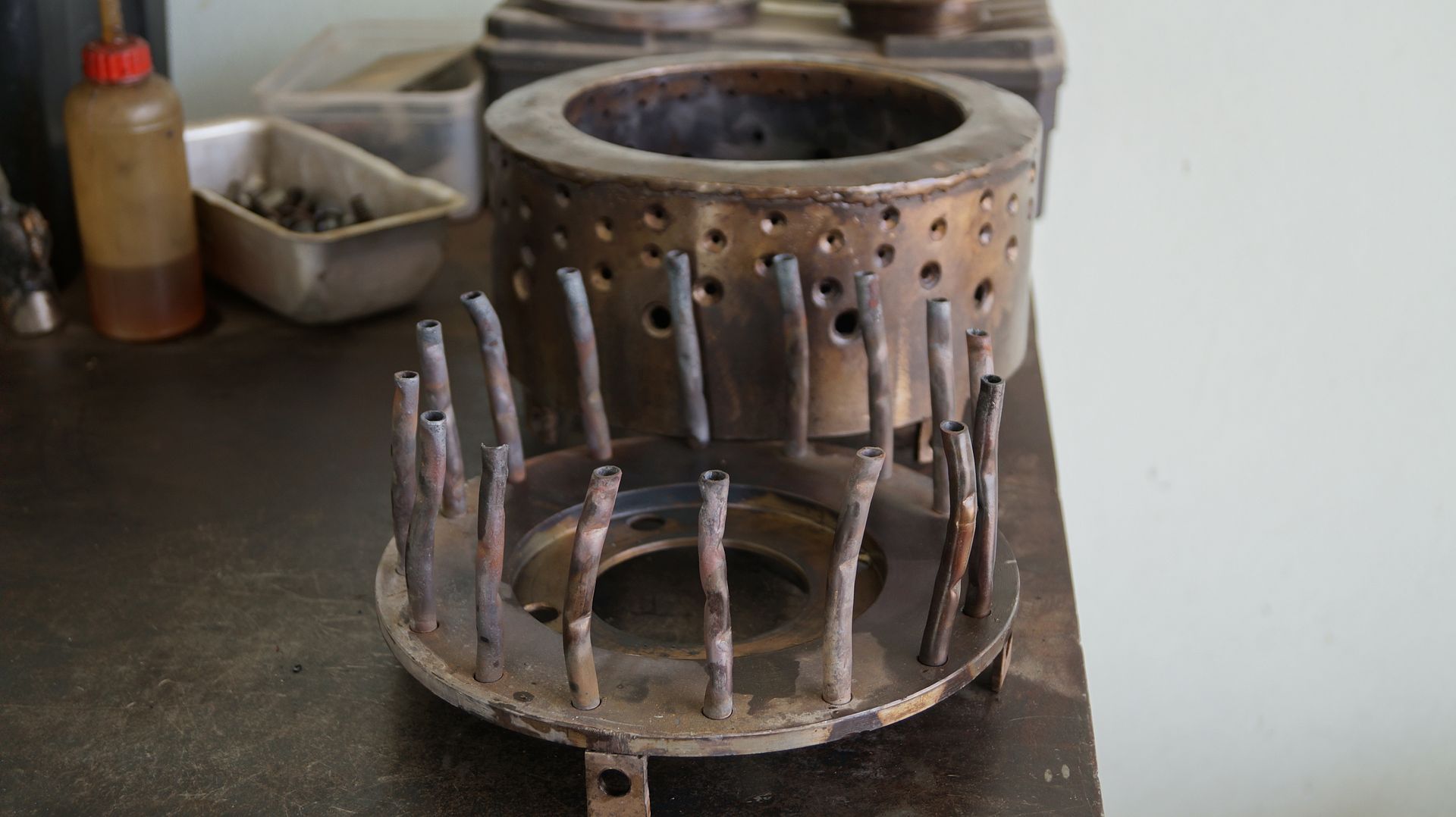 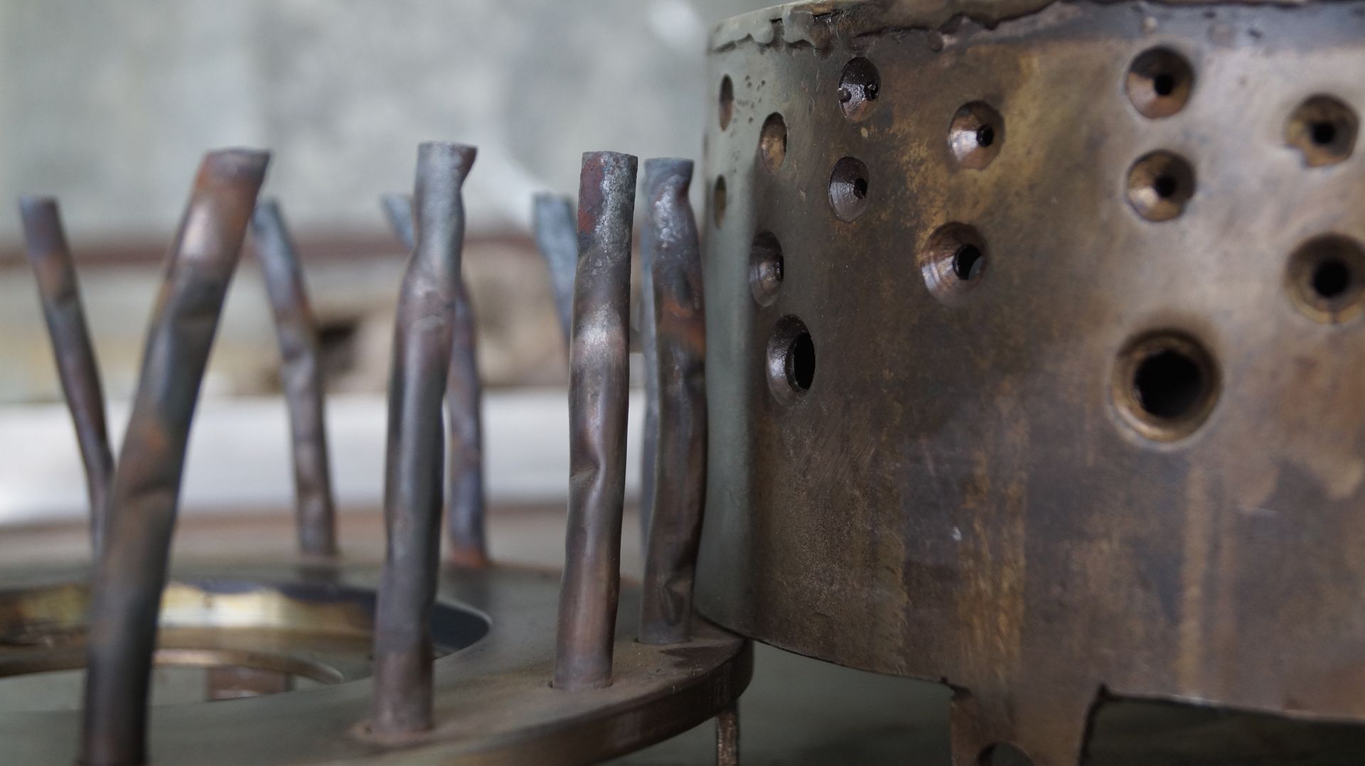 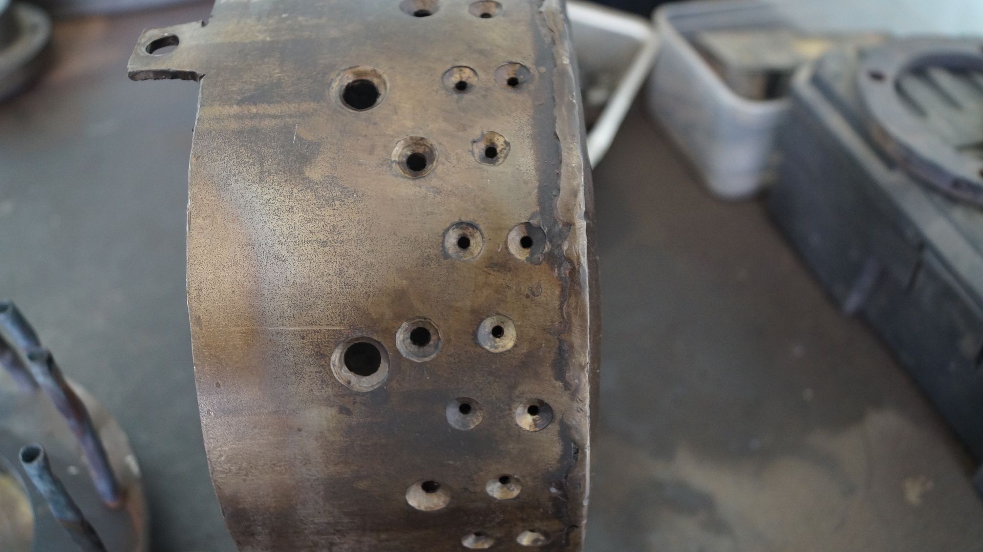 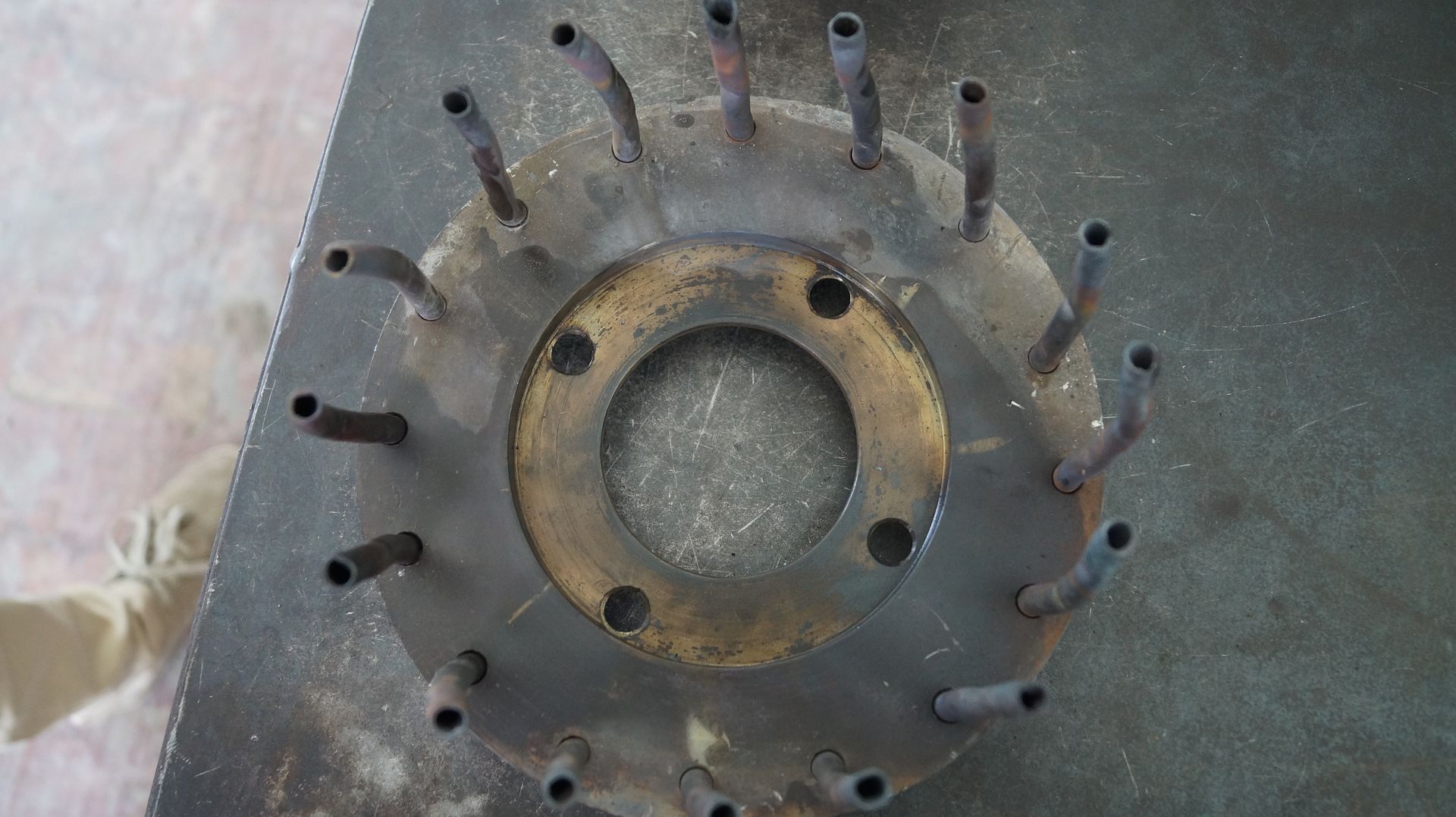 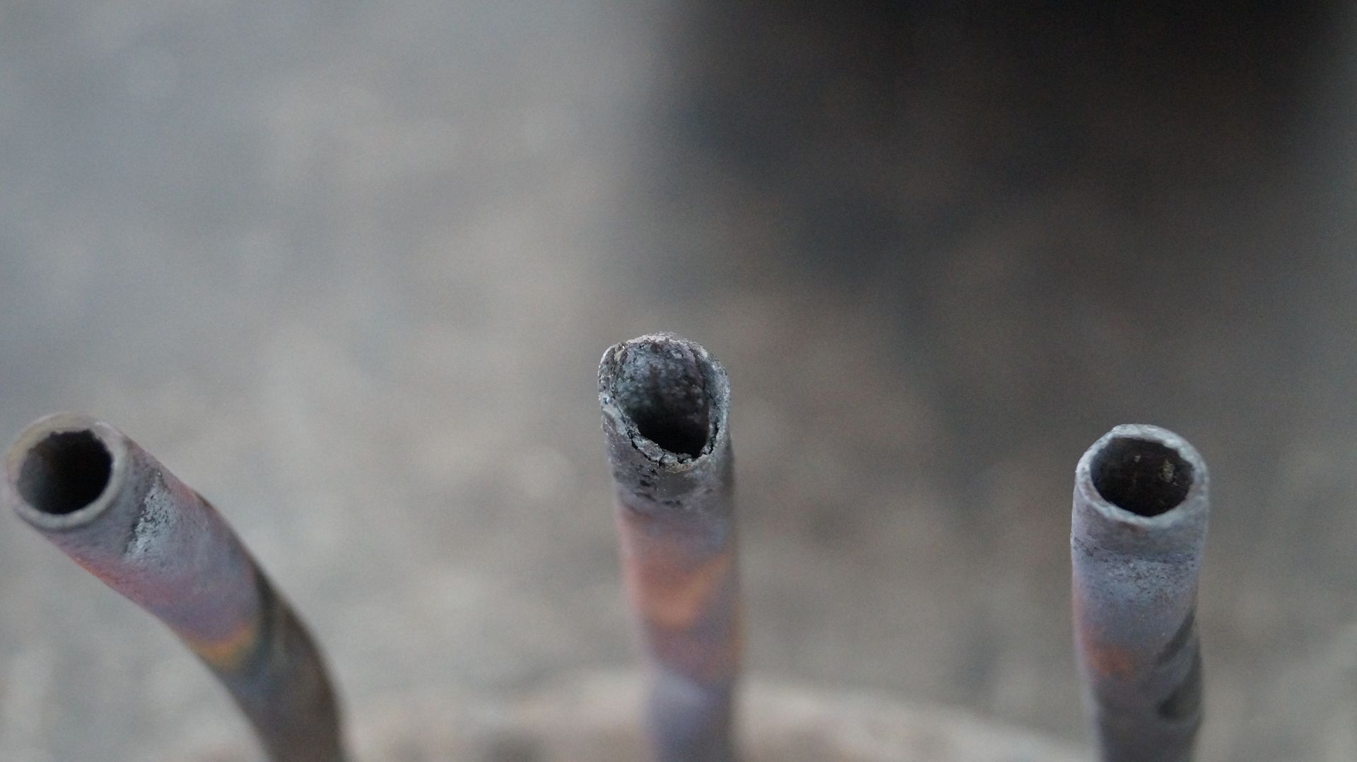 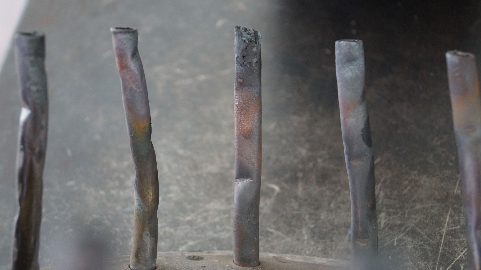 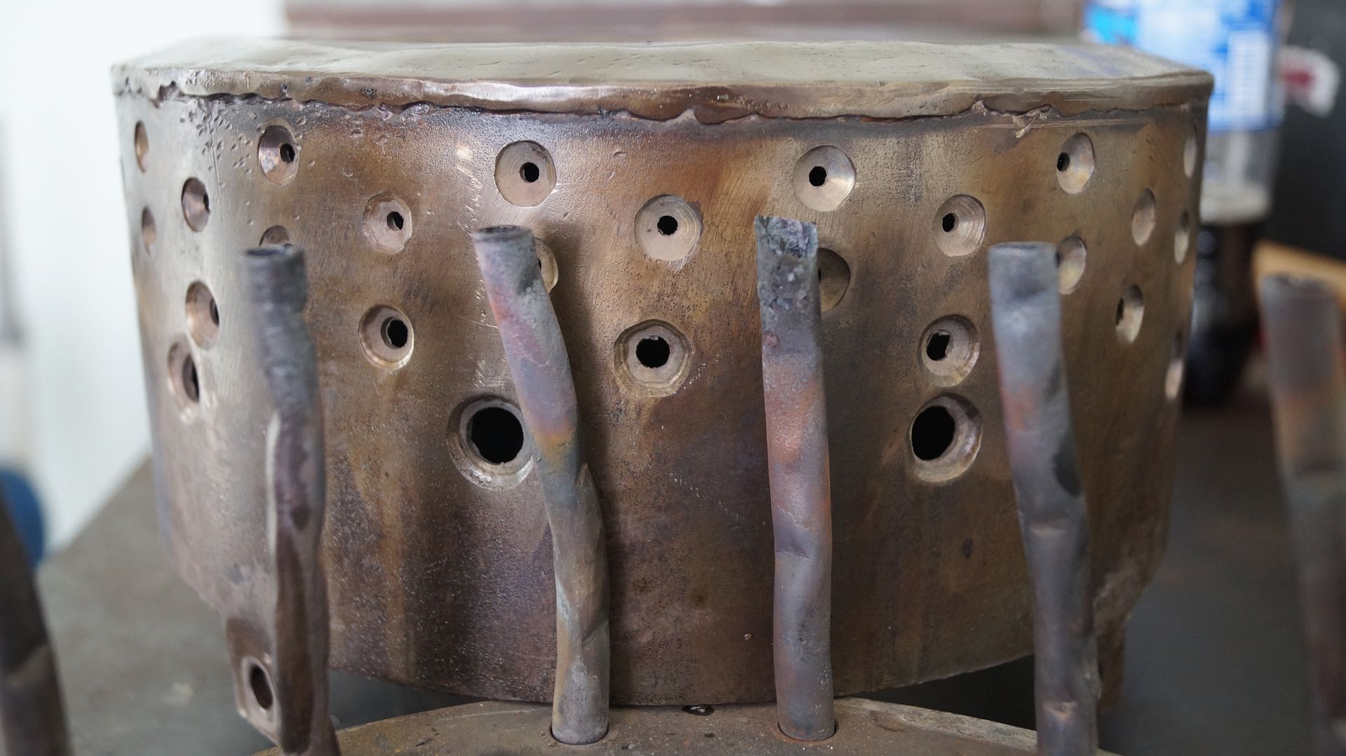 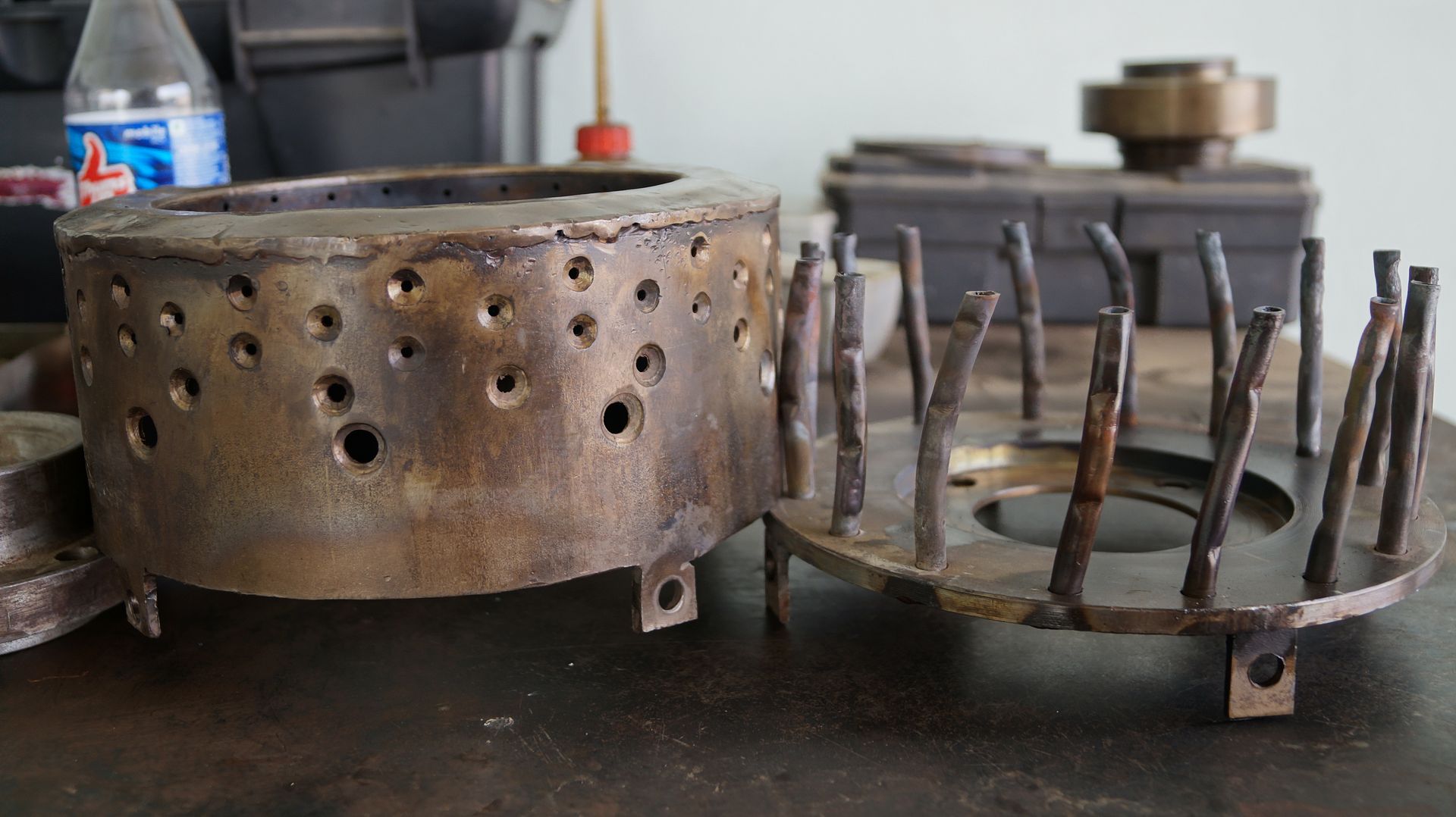 Cheers, Patty |
|
|
|
Post by racket on Jun 14, 2015 1:48:34 GMT -5
Hi Patty
They have been hot .
Why do they have bends in them ??
What ID are the evaporators ??
Why are your main dilution holes so far up the flametube wall ??
There doesn't appear to be any "gaps" in the hole spacing opposite the evaporators , are there any evaporators with air blowing on them through holes, alignment is critical ??
With 16 evaps , why don't you have 16 main dilution holes , one between each evaporator ??
Could you please give me the size and number of holes in each row , both inner and outer walls ??
Your inner FT wall appears to have more heat colouration than the outer wall , is this a correct assumption ??
Some evaporators appear to be more heat affected than other , any idea why ??
Cheers
John
|
|