|
|
Post by madpatty on Jun 16, 2015 23:55:43 GMT -5
Hi Racket,
The evaporators have bends so that diesel in no way can escape straight and has to hit the walls.
The evaps are 6mm ID.
The main body of the combustor is about 70mm.
The outer wall is 90mm long(from head end till NGV end axially).
The inner wall is 70mm from head end till NGV start.
In the primary zone there are total 96 holes of 3mm dia......(48/3 in first three rows of outer can and 48/2 in first two rows of inner can)......
In secondary zone ther are total 24 holes of 5mm dia.....(16 in fourth row of outer can and 8 in third row of inner can)......
In tertiary zone there are 18 holes of 9mm dia....(10 in last row of outer can and 8 in last row of inner can).....
The tertiary holes were placed axially according to the main body of the combustor i.e 70 mm but now i think they should have been placed according to the total length i.e 90 mm.
There are some holes at various zones blowing air on evaps.(so no set of holes primary , secondary or tertiary should blow air directly on evaps??)
The tertiary holes are 9mm in dia. So according to the calculated area i only needed 18 of them.
How can i place 16 holes in outer wall alone. I will have to reduce the size of the holes so that i can place 16 holes in outer wall alone.
I think 9mm is already just enough for the tertiary hole sizing.
I want to re-design the combustor for diesel use.
What changes you suggest??
Regarding holes sizing and placement.
Cheers,
Patty
|
|
|
|
Post by racket on Jun 17, 2015 0:59:03 GMT -5
Hi Patty Some suggestions ............. Keep the evaporators straight but with "D'ing" to produce the turbulence , bend the injector to squirt against the ID of the evaporator . Evaporators must be made of 304 stainless steel or better quality. Evaporators ID area need only be 10-12% of total hole area , currently with 16 X 6mm , the 450 sq mms represents ~16% . The total heating surface of the evaporators ( OD area) must be 6 times inducer area , currently >7 times if 50 mm long , so potential overheating . The larger tertiary holes need to be positioned as far downstream as possible to allow time for combustion to be completed before they add extra cooling air , position them so they blow straight radially into the NGV , have a look at my 10/98 flametube for ideas jetandturbineowners.proboards.com/thread/19/10-98-engine . When constructing the flametube determine the number of evaporators first with regard to flow area and heating surface , then with a marking pen scribe axial lines down your flametubes outer wall marking the positions of those "straight" evaporators . A small evaporator like your will only need to finish ~12mm from the front wall , so you need a Primary hole adjacent to the evap outlet ( so positioned on the marking pen line ~6mm from the front end wall) to blow through the outflow and start the mixing process, all other flametube holes, both inner and outer walls , need to be positioned exactly between the evaps , none must blow onto an evap . I'd suggest ring rows of 16 hole sets, 16 Primary , 16 Secondary and 16 Tertiary in the outer wall , and only 16 Primary and 16 Secondary in the inner wall. With the usual 30% area for Primary , we subtract the 10% for evaps so 20% left for the wall holes , assuming 16 inner and 16 outer , so 32 holes to add up to 460 sq mms , 14.3 sq mms/hole or ~4.25mm Dia , I'd go for 4 mm as your airflow is below optimum . Secondary holes , 16 X 4mm outer and 16 X 4 mm inner Tertiary , 16 X 9.5mm positioned as close to the rear wall of the flametube as possible so that they blow radially into the NGV . As for axially positioning of the holes .......... The outer wall will have the Primary holes at 6mm from the front wall so as to blow through the evap outflow , the inner Primary holes at 20mm from the front wall positioned between the evaps, this displacement further rearwards should produce some sort of recirculation in the head of the flametube to aid combustion. Secondary holes at ~ 50 mm from the front wall on the outer wall ( same as my 10/98 engines flametube) and a bit further rearwards on the inner wall . Tertiary holes as I've already suggested as far back as possible . All holes with some "bellmouthing" as per the current FT . Cheers John |
|
|
|
Post by madpatty on Jun 17, 2015 1:53:24 GMT -5
The total heating surface of the evaporators ( OD area) must be 6 times inducer area , currently >7 times if 50 mm long , so potential overheating . A small evaporator like your will only need to finish ~12mm from the front wall , so you need a Primary hole adjacent to the evap outlet ( so positioned on the marking pen line ~6mm from the front end wall) to blow through the outflow and start the mixing process, all other flametube holes, both inner and outer walls , need to be positioned exactly between the evaps , none must blow onto an evap . Hi Racket, The evaporators in my case start from the turbine end wall and end at about 15 mm from front wall so that means they are 75 mm long. Even if i make them to end at 12mm from front end wall then why the primary holes in the outer wall should ber placed at 6mm axially from the front wall, if we need to blow them directly at the evaporators discharge? Shouldnt they be placed at 10 mm from front wall axially? so that they are just at the edge of the evap ends. Moreover if i go by area then calculations show i need only 10 evaporator tubes as you suggested earlier. Then what can be done to cover the maximum circumference and get overlapping of the evap discharges.? Cheers, Patty |
|
|
|
Post by racket on Jun 17, 2015 4:57:12 GMT -5
Hi Patty
The air/fuel mixture will exit the evaporator at a fair velocity and will impact the front wall with any unvapourised fuel evaporating on the wall , by having the Primary hole relatively close to the wall it will "cut through" a larger volume of mixture allowing its placement to be less accurate ..............trust me :-)
As for your "coverage", thats a problem due to the unusual design , normally one would expect a flametube of 4 or 5 inch diameter for a compressor of your size rather than 8 inches , its a very large diameter with a rather skinny radial width , not conducive to simple solutions .
Your current evaps at 8mm dia by 75mm long will be overheating at the outlets unless theres very good inflow of air into them , so preferably a bellmouth inlet and no "D'ing".
The fact that you currently have D'ing of the evap tubing and their rather long length to ID ratio probably means the effective flow is roughly OK due to the "friction" .
The evaps aren't your problem , sure they're getting hot and are burning their ends but they'll be vapourising the fuel , your problem is the wall holes and their placement .
Cheers
John
|
|
|
|
Post by madpatty on Jun 21, 2015 3:00:20 GMT -5
Hi Racket,
I just sourced a gerotor pump that was being used as a lubrication pump in a tractor...
The doubt is how it can be used as lubrication pump in our case where pumps are to be mounted externally rather than in sumps...
Wont they leak from the shaft side where there is no seal??
What can be done?
Cheers,
Patty
|
|
|
|
Post by racket on Jun 21, 2015 3:25:37 GMT -5
Hi Patty
You simply add a seal to the shaft .
Cheers
John
|
|
|
|
Post by madpatty on Jun 21, 2015 3:27:44 GMT -5
Hi Racket,
But the shaft exit is towards the pressure side....how can a seal handle the pressure...
How do you use the subaru pumps or it is a different design altogether..
Cheers,
Patty
|
|
|
|
Post by madpatty on Jun 21, 2015 3:31:13 GMT -5
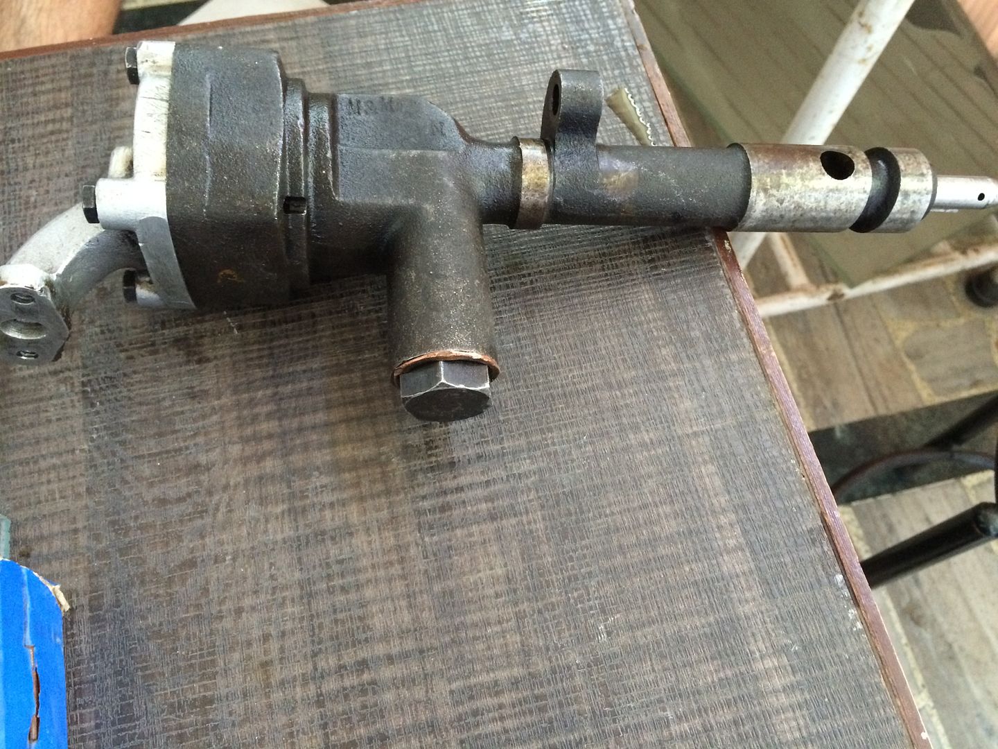 The hole in the extreme right is the pressure port and the aluminium joint on the left is the suction side.... The shaft exits in the right as u can see. 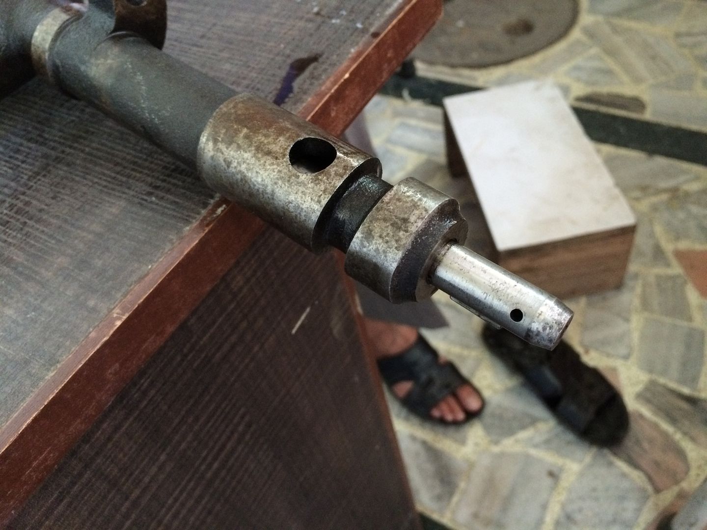 Cheers, Patty |
|
|
|
Post by madpatty on Jun 21, 2015 13:00:51 GMT -5
Hi Racket, some pics of the new combustion chamber made according to the guidelines:- 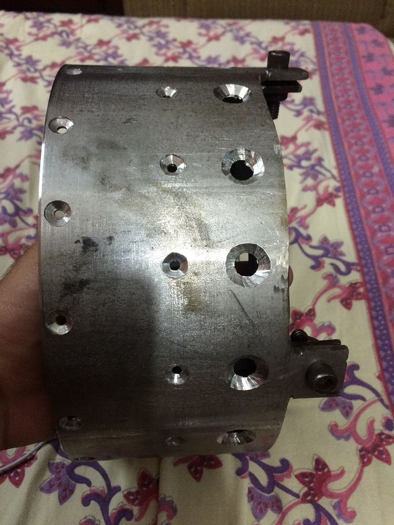 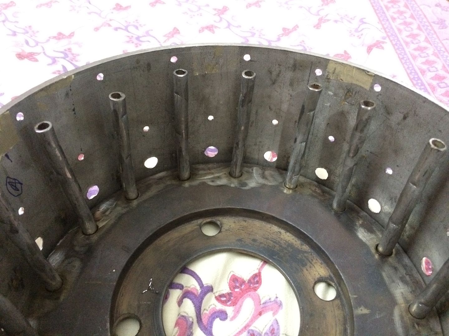 Cheers, Patty |
|
|
|
Post by madpatty on Jun 21, 2015 13:02:14 GMT -5
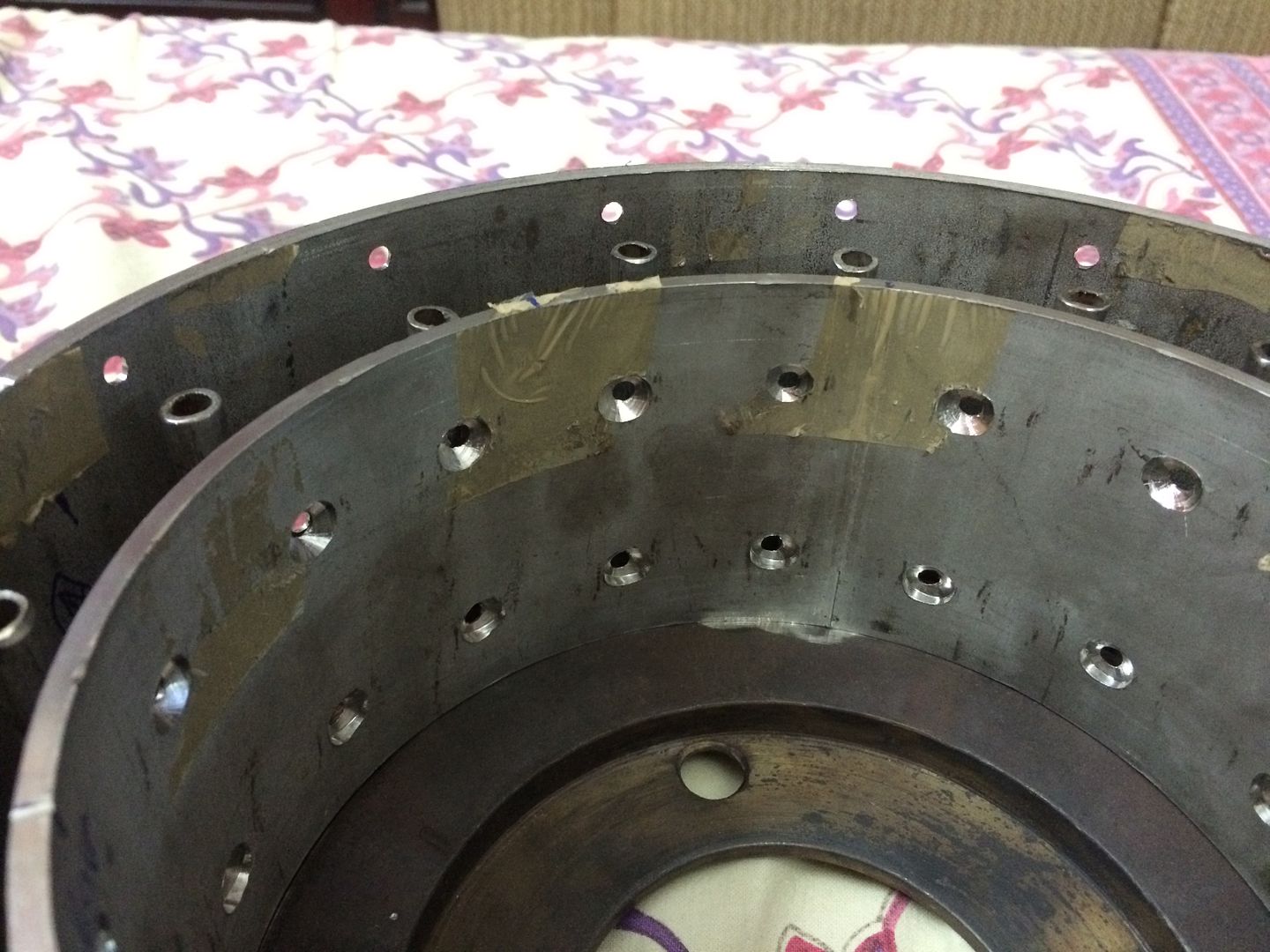 As compared to the old one:- 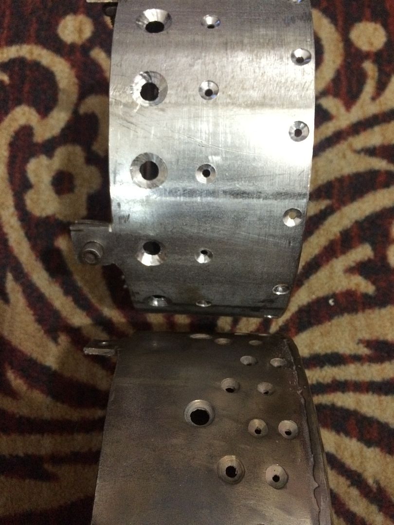 cheers, Patty |
|
|
|
Post by racket on Jun 21, 2015 16:55:10 GMT -5
|
|
|
|
Post by madpatty on Jun 21, 2015 20:26:14 GMT -5
Hi Racket,
I opened the pump up and realized that it can be used the other way way also in which it will be sucking from the right shaft end and pressure end will be the left aluminium port....
Actually i think the person i bought from was misguiding me...that pumps actual usage is this way only....
The inbuilt pressure relief valve gets activated when pressure acts on the aluminium side.
Moreover i think these pumps work equally well from both sides....
Cheers,
Patty
|
|
|
|
Post by madpatty on Jun 22, 2015 22:24:39 GMT -5
Hi Racket,
I was just having a look at your pump...
Where exactly is the pressure port?
What is that half circle slot just near the square shaft of the pump?
Is that a suction port or pressure port.
Cheers,
Patty
|
|
|
|
Post by racket on Jun 23, 2015 1:18:48 GMT -5
Hi Patty Maybe this pic will be more enlightening jetandturbineowners.proboards.com/attachment/download/22 , the smaller copper pipe ( 1/2" OD ) is the pressure line that runs to the top of the 10/98 engine , the larger 3/4" copper pipe is the suction line from the oil tank . I think I made a complete new end for the motor that incorporated the mounting for the oil pump as well as the suction porting to the pump , the pressure line comes off a port on the oil pump itself , theres a fair bit of work involved to couple the motor and pump , but it does end up a reasonable unit with filter and pressure relief valves all together in one unit , there is a bleed down plastic line at the coupling area to drain any oil bypass of the seal . Cheers John |
|
|
|
Post by madpatty on Jun 24, 2015 8:48:43 GMT -5
Hi Racket,
i did a test run with the new combustor and gaseous fuel.
Strangely there was a clear hot spot near the 1'o clock position when viewed from turbine end.
And more strangely this is the same position where my NGVs always get damaged due to overheating....
i have no reason why this region is getting hotter than anywhere else.
i have opened up the engine and clearly flame front had crossed the tertiary boundary at that very region as it appears from the heat patterns shown on the flametube. Other regions are fine.
Cheers,
Patty
|
|