|
|
Post by racket on May 3, 2015 16:51:22 GMT -5
Hi Alain
An axial LP compressor stage would be a better proposition for the tip jets as it can be run fairly fast but without the pressure rise of the centrif. wheel, but theres other constructional problems that could cause problems even if the flow/pressures were OK .
Sourcing a small enough axial stage would be very difficult , making your own a very big job :-(
I'd be interested to see your current calculations for the 2 comp wheel design to see if they can be "massaged" into something different .
Cheers
John
|
|
gtbph
Veteran Member

Joined: August 2013
Posts: 101 
|
Post by gtbph on May 4, 2015 3:48:13 GMT -5
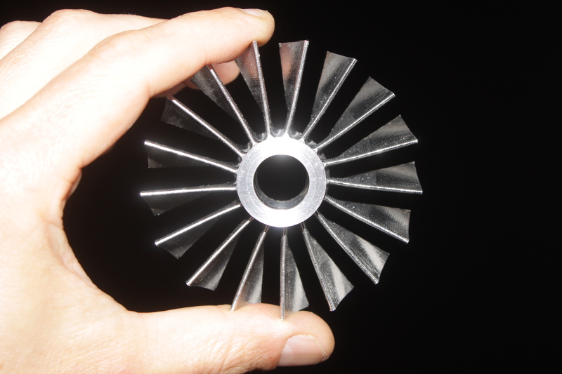
Hi John, Maybe I could cut away more from a big wheel, something like this?  And here is is my turbine calculator. The yellow cells are inputs. I could not attach it here, if I press "Add Attachement" nothing happens, so I uploaded it here: www.docdroid.net/z9lb/turbinecalc-08-clr.xls.htmlThe online preview is a bit strange, but you can download and save it, then it looks normal. Cheers, Alain |
|
|
|
Post by racket on May 4, 2015 23:47:31 GMT -5
Hi Alain
I've had a look at your numbers and I'm wondering why you aren't having full expansion through the turbine wheel , is there a need to have some thrust ??
Also your turbines tangential/tip velocity has me querying the numbers , it appears as though your gas velocity is slower than the blade tip .
I'm having some difficulties getting my head around your numbers as I normally work in Imperial units rather than SI
Cheers
John
|
|
gtbph
Veteran Member
Joined: August 2013
Posts: 101
|
Post by gtbph on May 5, 2015 5:28:13 GMT -5
Hi John, Thanks for having taken a look at my numbers. A bit thrust is needed for yaw control and it's ok if it pushes forward a bit. The turbine section of my sheet is based on an example radial turbine sizing calculation from a book. In the book, they start with a PR and power requirement, and calculate an optimal wheel size and speed from it. I reversed that and start with a size and speed, and calculate the optimal PR and power produced from it. I think the turbine stage could also have a different PR, but the calculated value would have the best efficiency. That's why I'm planning with this value at the moment, I can adjust the nozzle size later if needed. Yes, the gas velocity is slower than the blade tip, this is what Chris explained here: jetandturbineowners.proboards.com/post/10747/threadThe formula in my book is a bit different from what Chris used. With his formula, the gas incidence angle is 36° for 10 blades, the formula from my book gives 28°. Chris also quoted other values from 20°-40°. I'm trying to get that sheet right for quite some time now, but I'm still very unsure about it. I guess at some point I will have to let go and just build the damn thing  . Cheers, Alain |
|
|
|
Post by racket on May 5, 2015 16:42:51 GMT -5
Hi Alain
Be careful about using old turbine theory , its generally based on low Trim turbine wheel shapes ( <40 Trim ) unlike our turbocharger wheels which are generally large Trimmed like yours at 80 Trim.
When I get some time I'll have another look at your numbers , but we generally run higher gas speeds than tip speeds otherwise we can't get the pressure drops required , a choked NGV is going to be producing gas velocities of ~2,000 ft/sec , if at a ~20 degree above the tangent , then the tangential will be close to 1,900 ft/sec but turbine tip will be only 75% of that , so theres a big "impulse" on the blade tip .
Yes,sometimes we can do too much theory and never get anything built
Cheers
John
|
|
|
|
Post by finiteparts on May 5, 2015 20:59:26 GMT -5
Alain, Have you sketched out your vector triangles? I plugged in your numbers and got something like this...  I have wavered on the amount of negative incidence to set for the design point condition, and I tend to lean towards Colin Rodgers or Nick Baines work (-20 to 25 degrees). Rodgers worked for a long time at Solar turbines and now acts as a consultant and Baines is a turbocharger design expert (http://www.amazon.com/Fundamentals-Turbocharging-Nicholas-C-Baines/dp/0933283148), and I feel that their data more aligns to our work. That being said, my design point is around -25 degrees....so I would agree with the 28 degree incidence that your book provides. Good luck! Chris |
|
|
|
Post by racket on May 6, 2015 0:53:57 GMT -5
Hi Alain
Your horsepower numbers align pretty close to my rougher methods of calculation , within a couple of horsepower one way or the other, nothing to worry about there .
But its that LP comp diameter thats the sticking point , you indicate a tip speed of 418m/s - 1370 ft/sec which would be producing an ~ 2.5 :1 PR rather than an ~1.5 design , this would make for a 50 horsepower shortfall in the power from the turbine to spin it ...............you need that tip speed down below 1,000 ft/sec , probably closer to 850 ft/sec - 260 m/s
Cheers
John
|
|
gtbph
Veteran Member
Joined: August 2013
Posts: 101
|
Post by gtbph on May 6, 2015 17:34:09 GMT -5
Hi Chris,
Thanks for these informations, and for your small turbines thread too, that's very interesting!
Yes, it's logical to use Baines' data if he is a turbocharger design expert, I'll use that too.
In the velocity triangle, why is the angle 33°?
atan(92/170)/Pi*180 = 28.4°
You wrote about a design software you're making, will that be available for others, or is it for your projects?
Cheers, Alain
|
|
gtbph
Veteran Member
Joined: August 2013
Posts: 101
|
Post by gtbph on May 6, 2015 17:40:53 GMT -5
Hi John, It's good to hear that our numbers are close, with this I can be sure that my turbine could be made to work, because you have proven it many times.  Yes, the LP wheel is the biggest problem at the moment, I understand it will not work with a radial wheel with the mass flow and speed I'm planning. I'm still hoping an axial wheel could work, but I need to read a bit about axial wheels before I can say anything about it. In the meantime I want to experiment with recirculating spray nozzles, to see how they work. Cheers, Alain |
|
|
|
Post by racket on May 7, 2015 0:04:42 GMT -5
Hi Alain
With your LP compressor wheel , if you only want a 1.5PR the inducer will probably need to be considerably larger than your current design if using a normal turbo compressor wheel as the inducer angles will be at an incorrect angle if using the smaller inducer resulting in very poor compressor efficiency as you would be running in a choke region of the map .
But you would also be needing those lower rpm to reduce tip speed and max PR .
If you want to use an axial comp wheel and still produce a 1.5PR from a single stage ,then the wheel will need to be a transonic type , this is starting to become an even more difficult wheel to source .
More thinking required :-)
Cheers
John
|
|
|
|
Post by finiteparts on May 7, 2015 20:39:48 GMT -5
Hi Alain, Sorry about that! I hit arcsin instead of arctan...my quick little scribbled vector triangles are rotated on the paper and I must have confused the relative velocity vector as the base and not the hypotenuse. But, luckily I have an out...since I did state, "...something like this..." Ha! My "design" software is an ever expanding MATLAB M-File...I was just talking to a coworker today making fun of how I now understand how Microsoft can have such boated operating systems, since it's hard to go back and redo code that is far from streamlined. When I get it to a point that it might be usable for others I will probably post it on MATLAB's File Exchange. I really need to rewrite it so it has a better structure...the truth is I would be embarrassed to post it on the File Exchange as it is today. I also try things out in Excel such as the constant temperature lines to plot over the compressor map, that I need to "pull-into" the M-File...so there is still a lot to do. I quickly looked through your worksheet and it looks pretty good. I didn't check formulas or anything, just looked at the calculation steps and I think you have a good approach. Did the book you are using have the NGV efficiency in it or did you add that in? I don't have a copy of that book, but I might have to check it out, it looks like a good resource. I just finished going through two more papers by the guys out at Queen's College in Belfast that put out the paper on the performance effects of varying vaneless space and vane solidity in radial inflow turbine stators (posted about here: jetandturbineowners.proboards.com/post/11041 ). The papers I just went through go into the perforamnce effects of the NGV discharge area on mass flow, pressure ratio and turbine efficiency, while the second paper looks at the effect of turbine off incidence entry. It aligns well with the number that you chose for your turbine inlet relative flow vector, so that good! I will try to summarize the data they presented and get it up over the weekend if I have time. John, what are you referring to here, "...Be careful about using old turbine theory , its generally based on low Trim turbine wheel shapes ( <40 Trim ) unlike our turbocharger wheels which are generally large Trimmed like yours at 80 Trim."? I went through his worksheet and I can't see anything that fits that statement. Good luck! Chris |
|
|
|
Post by finiteparts on May 7, 2015 20:58:09 GMT -5
What are you referring to when you say "recirculating spray nozzles"? Are you referring to bypass style fuel nozzles? Because I am a fan of those. I used one on our Senor Design Project at school and it worked great. I had some links on this post: jetandturbineowners.proboards.com/post/8402~ Chris |
|
|
|
Post by racket on May 8, 2015 0:18:04 GMT -5
Hi Chris
It was a generalisation, I wasn't specifically referring to Alains calculations , just about reference books .
A lot of the turbine theory I've seen uses radial inflow wheels of low Trim which can have different velocity triangles to our large Trim wheels , a low Trim wheel will probably be more efficient than a large Trim wheel , exactly the same as with compressor wheels when theres largish pressure ratios , imagine how efficient an 80 or 84 Trim compressor wheel would be at a 3:1 PR , generally a 56 trim is about as big as they get.
A radial inflow wheel needs a certain gas deflection to produce power the same as with an axial wheel , but a radial has a smaller blade speed component at the exducer due to the smaller diameter.
When I've tried doing velocity triangles for an inflow wheel they get rather complicated compared to an axial wheel , the inflow part is easy but the outflow gets a tad more complicated when you require a certain gas deflection in conjunction with a certain blade speed to power the compressor wheel , I've never been able to have a tangential gas velocity less than the blade tip speed .
A lot will depend on the inlet and outlet areas of the wheel and the exducer angles , I guess theres "ideal" and then theres "real world" where we have to use what we have , also turbo wheels are more particular about moments of inertia than a turbine would be so the turbo turbine wheel is designed as a different beast.
Cheers
John
|
|
gtbph
Veteran Member
Joined: August 2013
Posts: 101
|
Post by gtbph on May 9, 2015 4:51:06 GMT -5
Hi Chris, Working as a developer, I know exactly what you mean! When somebody needs a change that would affect code I've written 10 years ago, I try to say the feature they want is impossible or unreasonable, and sometimes it works  I'd bet Windows still has code from DOS hidden somewhere. Matlab would be a great program to have! While searching for axial compressor design texts, I found this: www.lth.se/fileadmin/tpe/Axial_Flow_Compressor_Mean_Line_Design.pdf It includes a complex simulation script written for matlab! I have to check out how expensive matlab would be, maybe it would be worth buying. Yes, the book uses a 2% NGV pressure loss. Thanks for the link about vaneless space, such gidelines are very useful! A summary of the two papers would be great, of course! But it's already very helpful that you compared my vector to the data from the paper, thanks! Yes, I meant "bypass style fuel nozzles", I'm not a native English speaker, so sometimes I use the wrong words. I want to try to build one myself, as a test. It would be great if I wouldn't need propane to start the engine. Cheers, Alain |
|
gtbph
Veteran Member
Joined: August 2013
Posts: 101
|
Post by gtbph on May 9, 2015 4:53:00 GMT -5
Hi John, When looking at the map for a Garrett 74.7/102.3 wheel, at 100000 RPM, 75 lb/min lies at 74% efficiency with a PR of 4. I was thinking that if I cut that wheel like shown above, the flow might stay the same, and just the pressure would be reduced. But that's a wild guess, of course, it could be very wrong. So yes, I agree, "more thinking required" , I didn't have the time yet to try to calculate an axial wheel. Cheers, Alain |
|


 .
.

