|
|
Post by racket on May 9, 2015 21:52:43 GMT -5
Hi Alain
Your inducer tip on a 74.7mm diameter at 100,000 rp is already travelling at ~1280 ft/sec , once the air has entered the inducer its being accelerated to roughly that velocity , this is ~50% too fast for a 1.5 PR :-(
Cheers
John
|
|
gtbph
Veteran Member

Joined: August 2013
Posts: 101 
|
Post by gtbph on May 10, 2015 14:52:40 GMT -5
Today I made some parts and a tool for the bypass nozzle test:  On the left, there is the outer case of the nozzle, it's 10mm long, diameter 6mm, nozzle exit 0.5mm, hole 4mm. Inside this case there will be the part shown in the middle, this will be the bypass and there will be some channels, which I will make using the tool shown on the right. It's a 0.5mm slot mill, diameter 8mm. Making of the tool:   The next step will be to harden the tool, it's made from "silver steel" (I don't know if it's called like this in English). This steel has to be heated to only 820°C to harden, with this low temperature it doesn't distort too much when quenched. Alain |
|
|
|
Post by Johansson on May 11, 2015 0:16:09 GMT -5
Nice machining, DIY tool making is very interesting to watch.
|
|
gtbph
Veteran Member
Joined: August 2013
Posts: 101
|
Post by gtbph on May 11, 2015 12:23:25 GMT -5
Thanks Anders  ! I used my newly bought Sandvik lathe tools for this, they're awesome! |
|
gtbph
Veteran Member
Joined: August 2013
Posts: 101
|
Post by gtbph on May 15, 2015 8:50:12 GMT -5
After oil quenching, annealing at 220°C and sharpening, the slot cutter is finished.  This is the inner part of the nozzle, it has 6 spiral slots now that create a vortex in the fluid.  It's a bit like a radial turbine with an NGV but without a wheel. When the fluid is pushed inwards by the pressure, it wants to accelerate. If there is a wheel, this "acceleration" is absorbed by the wheel, creating torque, but here without a wheel, the fluid can accelerate freely, creating a very high rotational velocity. This tears the fluid apart when it exits the nozzle. Here a test with tap water:  with the bypass opened a bit:  I think it looks ok, but I'll have to test it with higher pressure, and with diesel or kerosene. The flow was about 10L/h, that's a bit too much. I need about 35L/h for the engine, with only 4 nozzles I would already have 40L/h, but 4 nozzles is not enough for an annular combustor I think. But I'll test it with diesel first, maybe the flow will be lower Cheers, Alain |
|
jetric
Veteran Member
Joined: December 2014
Posts: 132
|
Post by jetric on May 15, 2015 20:30:33 GMT -5
Hi Alain, You could of done it the easy way both Danfoss and Monarch make a range of bypassing oil burner nozzles you can buy off the shelf, The nozzles are reasonably priced but the nozzle holder is over priced for what it is but a man of your skills could easily machine a nozzle holder up. On my first DIY jet engine i used a bypass nozzle that i had made from modifying a standard Danfoss oil burner nozzle it is still fitted to my engine and has been working perfectly for the past fifteen years. The bypass nozzle is a realy good idea because it provides a realy fine spray pattern over a very wide flow range, Here's the information sheet for the Monarch bypass nozzles;  Rich. After oil quenching, annealing at 220°C and sharpening, the slot cutter is finished. This is the inner part of the nozzle, it has 6 spiral slots now that create a vortex in the fluid. It's a bit like a radial turbine with an NGV but without a wheel. When the fluid is pushed inwards by the pressure, it wants to accelerate. If there is a wheel, this "acceleration" is absorbed by the wheel, creating torque, but here without a wheel, the fluid can accelerate freely, creating a very high rotational velocity. This tears the fluid apart when it exits the nozzle. Here a test with tap water: with the bypass opened a bit: I think it looks ok, but I'll have to test it with higher pressure, and with diesel or kerosene. The flow was about 10L/h, that's a bit too much. I need about 35L/h for the engine, with only 4 nozzles I would already have 40L/h, but 4 nozzles is not enough for an annular combustor I think. But I'll test it with diesel first, maybe the flow will be lower Cheers, Alain |
|
gtbph
Veteran Member
Joined: August 2013
Posts: 101
|
Post by gtbph on May 16, 2015 11:36:39 GMT -5
Hi Rich,
Thanks for your help. It's good to hear they worked so well and reliably in your engine! The main reason I made one myself is that I think the professional nozzles are a bit big. This one is just 6mm in diameter. But on the other hand, the bought ones surely make a better spray, and are more durable. If the tests show some problems, I'll try with these.
Cheers, Alain
|
|
gtbph
Veteran Member
Joined: August 2013
Posts: 101
|
Post by gtbph on May 16, 2015 11:41:09 GMT -5
Hi John, Your inducer tip on a 74.7mm diameter at 100,000 rp is already travelling at ~1280 ft/sec , once the air has entered the inducer its being accelerated to roughly that velocity , this is ~50% too fast for a 1.5 PR :-( Sorry I didn't answer for so long, I wanted to read more about axial wheels first, but I haven't made much progress there, so I post what I have at the moment. The reasons I think there should be a shape that works are: -When looking at different wheels, it seems to me all shapes are possible between a high-trim radial wheel on the "high pressure, low flow" side, and an axial wheel or even a propeller on the "low pressure, high flow" side. -I think in axial wheels the air is not accelerated much, I hope it's possible to have a low PR even with high tip speeds. I found a statement in a book saying a Mach number of 1.165 at the inlet of an axial compressor is no problem. This was for a 7-stage compressor with a PR of 4.15, so each stage should have a PR of about 1.22. -Transsonic inlet conditions with Mach numbers up to 1.2 and good efficiency seem possible with turbo wheels, if I didn't make a mistake. -I could add inlet guide vanes, to add swirl to the air before it enters the wheel, to reduce the Mach number. If I don't find some formulas I can easily apply, I think I'll just try to modify a wheel until I get something acceptable. The company with the billet wheels you linked earlier also makes custom wheels if I understood them right, maybe I could ask them to produce something for me. I could also try to make a wheel myself, I have 4 CNC controlled axis on my mill, maybe that's enough to make a simple axial wheel. Else I could buy a second round table to attach to the first one, then I would have 5 axis. As you see, I'm quite unsure still. I think apart from reading more, I'll try to make a milling program for an axial wheel, to see if that's possible at all. Cheers, Alain |
|
|
|
Post by racket on May 16, 2015 18:22:05 GMT -5
Hi Alain An axial wheel would be a better proposition as they'll produce a high flow rate at a lowish pressure which is ideal for your situation , but the rpm will still be a problem if you want direct coupling . There are Allison C18 and C20 axial comp wheel stages that would suit you , like this one maybe ........... www.ebay.com/itm/6876594-New-nos-Allison-250-C18-Compressor-Wheel-2840-00-242-4474-/131509422526?hash=item1e9e9289be&vxp=mtr , though this is overpriced for what is essentially just scrap without paperwork . The Allison axial wheels have rpm in the <60,000 rpm range , so you'd be needing a 2:1 redux from the gas producer An approach to an Allison/ Rolls Royce heli overhaul shop to discuss your plans/needs might result in some time expired compressor bits coming your way . There have been guys on the GTBA Site that have constructed small axial comps , but for your larger flow rates its probably easier to source a time expire Allison C18 or C20 wheel Cheers John |
|
gtbph
Veteran Member
Joined: August 2013
Posts: 101
|
Post by gtbph on Jun 10, 2015 16:00:12 GMT -5
Hi John, hi all, Phew, time flies! "Gas Turbine Theory (4th Ed.)" has some good formulas for axial wheels. I put some in a excel sheet, and made a C++ program to calculate the geometry. It outputs a script for OpenSCAD, and generates free vortex blades with a double-arc profile. The hub radius is a bezier curve. The blades are thicker at the root to carry the centrifugal load. This is how I think the wheel could look, but all parameters can be changed easily:   It's funny how everytime I think I got something, at the same time I discover at least two new problems.   So this wheel has many guesses in it, namely The length & number of bladeswhich are chosen just by the look of the wheel.  The blade count is low because of the small hub radius, and it's long so that the blades "overlap" a bit. The book says I should refer to cascade test data, but I don't have such data. The hub radius increasewas a straight line first, but it "didn't look right", so I used a bezier curve. The book doesn't say anything about that, maybe because "normal" axial wheels are much shorter than this. Pressure RatioA typical axial wheel produces a PR of around 1.2, but I want 1.45. I used a "trick" to solve that, I don't know if it can be done this way. The book has an easy criterion for when problems with flow separation arise: The "de Haller Number". It's very simple and says that the wheel-relative velocity of the air leaving the wheel should be no less than 0.72 times that of the entering air. The book chapter is about multi-stage axial compressors, and to simplify the design procedure it uses a constant axial velocity throughout all the stages. Now my "trick" is to let the axial velocity increase, such that the PR is high while leaving the diffusion in the wheel at an acceptable level. My wheel would produce more deflection but about the same amount of diffusion, than the examples in the book. The book aims at 50% reaction, here I would have more diffusion in the stator. Material stresswas calculated without considering the twist of the blades. The blade thickness increases such that the tensile stress would never exceed 80 N/mm^2, if there was no twist. Good alloys have a strength of about 500 N/mm^2. The next step will be to make a mill program. I hope it doesn't take too long, because the geometry calculations can be reused. I know this wheel will never be as efficient as a wheel from a real turbine, but compactness is very important for me. Efficiency is also important of course, but since this wheel is not part of the power producing section, a low-efficiency wheel will "just" produce less thrust for the rotor blades. That's not such a big problem, as it would be if the wheel for the power section was less efficient. Regards, Alain |
|
|
|
Post by finiteparts on Jun 10, 2015 22:07:29 GMT -5
Hi Alain,
That's a nice looking model...you are really getting up to speed on the design and the best part of making the programs is that you can "play" with the parameters to understand how they effect the component performance.
One thing you might want to add to your design is large fillets at the blade roots. The blades will pull, bend and twist during operation. All those loads are reacted through the material at the base of the blade and the fillet helps to "flow" that stress out to the hub. Without the fillets, the stresses will bunch up in the edges where the blade meets the hub, creating stress concentrations at those edges. Since the local peak stresses due to the bending moments and centrifugal loading can be substantially higher than the average in-plane tensile stresses, especially at the leading edge and trailing edge (or any other discontinuities in the load path), you should be careful using the average in-plane stresses to represent the actual loading that the blade root will see.
Peterson's "Stress Concentration Factors" can help you get a very rough idea on some of the local stresses and the effect of fillet sizing. The second thing that you might want to check is the fatigue life, since the blades will likely vibrate due to "passing" frequencies (such as stator vanes, etc). There will likely be a stress concentration at the leading edge root, the fatigue life will be based on that local stress level which will be much higher than the average in-plane stress and there is a potential to quickly loose blades in a relatively low number of fatigue cycles. The large a fillet will help to smear these peak local stresses out and help you gain fatigue life.
The blading looks good...newer engines use low aspect ratio blading like this in their one piece blisks (bladed disks), so the length and chord are not concerning. The double-arc blading is very old technology...you might try searching for controlled diffusion blading, which should help you get your stage pressure ratios up. I will look around to see if I have some cascade data for the CD blading. I would start my search at NASA's Technical Report Server.
What are the tip speeds?
Again, that is a good looking model. Keep up the good work and thanks for sharing!
Chris
|
|
|
|
Post by racket on Jun 11, 2015 5:09:27 GMT -5
Hi Alain
Sometimes on Ebay there are T700 engine first and second stage transonic blisks for sale for ~$200 , these have very high tip speeds of ~1500ft/sec for the 196mm dia first stage , but because of the very high airflow rates per square inch of inlet, the relative velocity is up closer to ~1700 ft/sec .
Inlet tip angle ~28degrees , with a virtually straight shape , whilst the root at ~100mm dia inlet is ~45 degrees , exit angles 28 tip ~80 root , theres a radial taper at both tip and root , with tip exit ~189mm and 110mm root .
Cheers
John
|
|
rythmnbls
Veteran Member
Joined: August 2011
Posts: 145
|
Post by rythmnbls on Jun 11, 2015 11:17:18 GMT -5
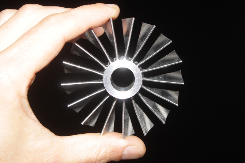
Nice work Alain. I've been playing with similar ideas. I have the axial compressor chapter from Gas Turbine Theory in a spreadsheet as well, plus I "lifted" a NACA airfoil generator from airfoiltools.com to generate the blading on a circular camber line. Here's a screenshot of a mockup of the first stage comp wheel.  For the blading sizes I used a pitch chord ratio calculated using "Howells correlation". You can read about here jetandturbineowners.proboards.com/thread/503/links in the 1241.pdf file. My next steps were to export a blade from the modeling software to Pycam and then on to the CNC, here's a test cut sample of the suction side of the blade machined into some scrap.  It's been a fun exercise up to this point, seeing if I could put together a tool-chain to produce a machined blade but I'm not sure I'd want to go all out and build a complete compressor. If I can be of any help just let me know. Steve. |
|
gtbph
Veteran Member
Joined: August 2013
Posts: 101
|
Post by gtbph on Jun 12, 2015 12:21:00 GMT -5
Hi Chris, Thanks! Yes it's fun to play with the parameters. Yes, I didn't think much about the fillets, I was thinking it's enough to avoid sharp edges. I'll use a 3mm ball nose cutter, this will automatically leave a fillet of 1.5mm radius. But now that you mention " large fillets" I will surely look closer, thanks for pointing it out. Peterson's "Stress Concentration Factors" looks very interesting. I'll add fillets to the model, to see how big they can be made without interfering with the air flow too much. It's good to know the aspect ratio is ok! I'll look into controlled diffusion blading, it sounds promising, I hope it's not too complicated. I completely forgot to write the numbers, tip speed is 367m/s (1204ft/s) Tip diameter: 70mm
Root dia. entry: 28mm
Root dia. exit: 41mm
Length: 25mm
Tip speed: 367m/s 1204ft/s
Axial velocity entry: 169m/s 554ft/s
Rel. gas v. at tip entry: 403m/s 1322ft/s Mach 1.216
Mass flow: 0.582kg/s
Alain |
|
gtbph
Veteran Member
Joined: August 2013
Posts: 101
|
Post by gtbph on Jun 12, 2015 12:23:48 GMT -5
Hi John,
Thanks for the dimensions of the T700 wheel! It helps me to get an idea of what the professional designers make. I found a few photos of such a wheel, but I'll make a model of it and post it here, so that we can visually compare the wheels.
I'm happy that my gas velocity is quite lower, it seems it's at least theoretically possible to make a wheel for this speed witout loosing too much efficiency.
Do you know if it's made of aluminium, or titanium?
Cheers, Alain
|
|


 ! I used my newly bought Sandvik lathe tools for this, they're awesome!

 So this wheel has many guesses in it, namely
 The blade count is low because of the small hub radius, and it's long so that the blades "overlap" a bit. The book says I should refer to cascade test data, but I don't have such data.


