gtbph
Veteran Member

Joined: August 2013
Posts: 101 
|
Post by gtbph on Apr 13, 2016 16:07:09 GMT -5
Thanks John, Anders and Miuge, Hi All
I also made a video while milling, not a powerful or precise machine, but for a low budget I'm happy with how it works.
Alain
|
|
|
|
Post by racket on Apr 13, 2016 16:31:48 GMT -5
Always fascinating to watch , thanks Alain , those curves would be a challenge on a manual mill
Cheers
John
|
|
gtbph
Veteran Member
Joined: August 2013
Posts: 101
|
Post by gtbph on May 9, 2016 15:28:01 GMT -5
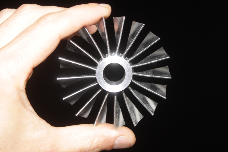
Last weekend I made the new IGVs, this time with NACA 4 digit profile. I guess a DCA profile would have been ok too since the incidence angle should always be zero, but because it is opposed to the centrifugal compressor inlet, I'm not completely sure if this will be the case. So to be sure I used a NACA profile. There's still some work to be done on the hub (a larger hole and other things), and also on the stator, but I still could not settle on a shaft design, so this will have to wait a bit. Something else that could be done, but I'm not sure if it is a good idea, is to use sand paper on the surfaces. It would remove the tiny "bumps", but maybe it would also change the shape a bit. Any advice? Last time I wrote that I use IGVs because of the reduced Mach number, but this is not the only reason. I forgot that IGVs are needed because this compressor is not a free-vortex design. A free vortex design is not possible because the blades of the rotor would be extremely twisted for the small diameter I'm using, and impossible to machine on my mill.   Next I'll make the rotor, I have bought a billet of 17-4 PH stainless steel ( a.k.a. X5CrNiCuNb16-4 / 1.4542 ). After precipitation hardening at 480°C for four hours it should have a yield strength of ~1400 N/mm². At about 16$/kg it was quite affordable, also available was X3NiCoMoTi18-9-5 / 1.2709 which would have been 60$/kg, but around 2000 N/mm² strong. Because 17-4 should also be less difficult to machine, I'll try with this. Alain |
|
|
|
Post by Johansson on May 9, 2016 16:00:42 GMT -5
Why do I feel the need to start giggling every time you post something like this? This is pure joy to read about Alain!
|
|
gtbph
Veteran Member
Joined: August 2013
Posts: 101
|
Post by gtbph on May 9, 2016 16:30:36 GMT -5
 Hmmm.... Maybe because nobody can tell for sure if I'm only slightly crazy or completely crazy (not even myself) ? 
|
|
gtbph
Veteran Member
Joined: August 2013
Posts: 101
|
Post by gtbph on May 24, 2016 7:23:47 GMT -5
This is the rotor. It's not finished yet, the leading edges need some work, and I'll polish the surfaces to remove some small errors. The "line" on each blade is there because the different cutters were not in the exact same position (Z axis). If I make another one, I'll have to rethink my method of measuring the position of the cutter. But the error is small, so I'll try to fix this wheel and use it. It's quite possible that a test will show that the design does not work as expected, so there's no point in trying to make a better wheel now.  The complete compressor looks like this, but the stator and IGV hub don't have the required taper yet.  Alain |
|
gtbph
Veteran Member
Joined: August 2013
Posts: 101
|
Post by gtbph on Aug 11, 2016 16:22:27 GMT -5
Hi guys, it's been a while, a few other things kept my busy lately, but I had a bit time to work on the engine now and then. Nothing is really finished yet, but I made pictures that I better post now, before they all get lost in the dungeons of my harddisk. Here's the video made while milling the compressor blisk. It's about the same as the other one about the stator, just that now there's oil cooling, and that my mill made rather frightening noises. But I'm very satisfied with the carbide mill bits, they have slightly different angles on every flute, this helps to reduce the vibrations. Also, that 17-4 steel is not as nasty as I first thought. I spent a few hours filing and sanding the blisk's front side, the back side is still the same.    This is a new tool for the lathe, a toolpost grinder. Earlier I used that hand-held part half visible on the right in the first picture, but the bearings are so tiny that they failed very quickly. Now it drives another shaft with larger, spring-preloaded bearings. Please forgive my ultra-crappy welding, I need more practice with TIG welding mild steel, obviously. There are two shafts, one to attach a grinding wheel for outer surfaces, and another one that can hold the small grinding tips with a 2.35 mm shaft, to grind holes.    First a try on the lathe tip which needed re-grinding anyway, then the turbine shaft was ground down to 12 mm to fit a ball bearing. Interestingly, the turbine shaft is not the same hardness everywhere: Where the brass bushings would be, it is hard, in between, it is softer.     Cheers, Alain |
|
gtbph
Veteran Member
Joined: August 2013
Posts: 101
|
Post by gtbph on Oct 2, 2016 14:37:56 GMT -5
On my lathe, it was not possible to make left-handed threads. The lead-screw was driven by three sets of exchangeable gears, so I needed to add a fourth small intermediate gear to reverse its direction. By the way, does anybody know why most of the turbos are made such that left-handed threads are needed? That doesn't make much sense to me, couldn't they make them to run in the other direction just as well? Anyway, this is the gear and parts needed:  Mounted to the lathe:  With that done, I could make the first part of the hollow shaft, there will be a second part welded on to this one:  It has a 1:20 taper, the turbine shaft was modified to have a taper too:  This is how the parts fit together:  It fits quite precisely, but when looking at it I have doubts if this will really work. I will not be standing next to it when testing, for sure! The compressor wheel has been modified too as you can see. The exducer was 88 mm and it is 80 mm now, such that it makes the right pressure. Because the turbine has to make enough power for the second axial compressor, it is better to use a low PR of 2.8, or else the radial compressor would need too much power. It also has a larger bore of 12 mm now, it was 8.25 mm before. The front, up to about where the splitter blades begin, has an even larger bore of 16 mm, this fits over the new shaft. I found an interesting site that explains the weakening effect of holes ( Link). The short version is: Assuming an infinite size plate, the hole size doesn't matter. The plate will be half as strong when pulled from all directions, and a third as strong when pulled from one direction, if there is a hole. When the plate has a finite size, the strength varies only with the amount of remaining material around the hole. For my modified compressor wheel I think this means that the back, where the "hub" diameter is big, has not been weakened much since 8.25 mm or 12 mm is not a large difference compared to the "hub" diameter. On the front it surely makes a difference, but I hope the stress is much lower there to begin with. Alain |
|
Chuks
Senior Member
Joined: August 2015
Posts: 498
|
Post by Chuks on Oct 2, 2016 18:45:25 GMT -5
hi Alain!
I must say you are doing a very high precisioned work, your works are very clean, looking forward to see the final look of this awsome engine,
keep the pics/knowledge coming.
could you tell me the technics you used in enlargining that comp wheel? I mean clamping it on lathe without missing alignment?
|
|
|
|
Post by racket on Oct 2, 2016 19:34:45 GMT -5
Very nice :-)
|
|
gtbph
Veteran Member
Joined: August 2013
Posts: 101
|
Post by gtbph on Oct 3, 2016 14:39:06 GMT -5
Thanks John!  Hi Chuks, Thanks! I tried to make these parts as precise as I could because they are a part of the rotor, for other parts I'll not care that much and try to be a bit faster in making them. The wheel looked like this originally: ( ebay link) - It has an integrated thread so I screwed it onto the turbine shaft tightly, and put the shaft between the points of the lathe (a bit like on this picture). - The outer diameter was reduced in small steps. - Then I clamped it in the lathe chuck without caring about the alignment, and drilled into the thread to remove it, but not further. - Now I could slide the turbine shaft into the wheel from the front end because the thread was gone, and align the wheel using the live center point, and clamp it. I guess this has made it roughly aligned, but I will need to re-balance it anyway because of the removal of metal, so I hope it does not matter if it was slightly mis-aligned. - The bore was opened to 10 mm with a drill, then to 11.75 mm with a boring bar, and finally to 12 mm with a reamer. The 16 mm part of the bore was again made with the boring bar. English is not my first language, so maybe I used the wrong terms, just ask if anything is unclear. Cheers, Alain |
|
Chuks
Senior Member
Joined: August 2015
Posts: 498
|
Post by Chuks on Oct 4, 2016 20:28:40 GMT -5
thanks alain,
its a bit clear. i think i have to try it first and see. am not too good yet on lathe yet so i will be having troubles trying.
cheers
Chuks
|
|
gtbph
Veteran Member
Joined: August 2013
Posts: 101
|
Post by gtbph on Apr 1, 2017 9:45:51 GMT -5
Time for an update! My wife and I had a baby in December, so there was not much time left to build my engine, but over time a few things could be done. The second piece of the shaft...  ... has a left-hand thread inside...  ... and was welded to the first piece.  The above picture shows the first welding pass, I made a second pass because I suspected the penetration was not deep enough despite me having tested it before. That second pass however was a bit too hot, I nearly burned a hole into the shaft and had to make a third pass to add a bit material. Then the nearly final size (plus ~0.02 mm for polishing), two threads and other features were machined. The idea behind this design with the long thin piece going through the shaft (see a few posts earlier) is to heat the thin piece before screwing it in. Then it cools down and contracts, pulling the tapers firmly together. I calculated that a temperature difference of 70°C should result in a tension of about 168 N/mm^2, about 475 kg in this case. To disassemble it I would heat both pieces and then rapidly cool the outer shaft, hoping that the thin rod stays warm enough to loosen the connection. At least, that's the theory. This is my new oven that I could buy cheap, it should be capable of 1200°C, and the automatic temperature control seems very accurate. The wheel and shaft have been hardened at 500°C for 4 hours. (I found out that the hardest "temper" at 480°C is not recommended for cold temperatures, and the air could get quite cold at the inlet)  The hardened pieces  After some polishing and machining  The back side of the wheel has a small taper that should improve the transfer of torque to the nut, the nut is the only thing that locks the wheel.  This is how it looks when put together, I still need to make various nuts and spacers.  Alain |
|
|
|
Post by Johansson on Apr 1, 2017 11:05:03 GMT -5
Congratulations to the baby!
Your work is looking great, a fascinating configuration of the rotary parts.
Cheers!
/Anders
|
|
gtbph
Veteran Member
Joined: August 2013
Posts: 101
|
Post by gtbph on Apr 1, 2017 14:59:05 GMT -5
Thanks Anders! The plan is to let the axial compressor blow forward into the hollow rotor mast, then through the rotor blades to the tip nozzles. The exhaust goes backwards and makes some forward thrust and allows yaw control with a small rudder in the exhaust jet.
Cheers, Alain
|
|


 Hmmm.... Maybe because nobody can tell for sure if I'm only slightly crazy or completely crazy (not even myself) ?


