|
|
Post by jetjeff on Jan 20, 2016 3:24:51 GMT -5
This turbine may be even too large for your super sized impeller   Jeff |
|
|
|
Post by Johansson on Feb 3, 2016 14:56:02 GMT -5
I sort of lost momentum with the JU-02 build when I realized that my lathe was too small for the job, my father who lives 200km north of here has a larger lathe which I will "borrow" from him next summer when I can find a truck large enough to take it. 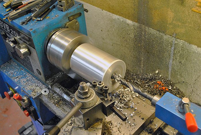 A couple of days ago I suddenly realized that I can actually do most of the job on my rotary table in the mill, an added bonus is that I can do both drilling, milling and turning without removing the parts. So, time to get busy!  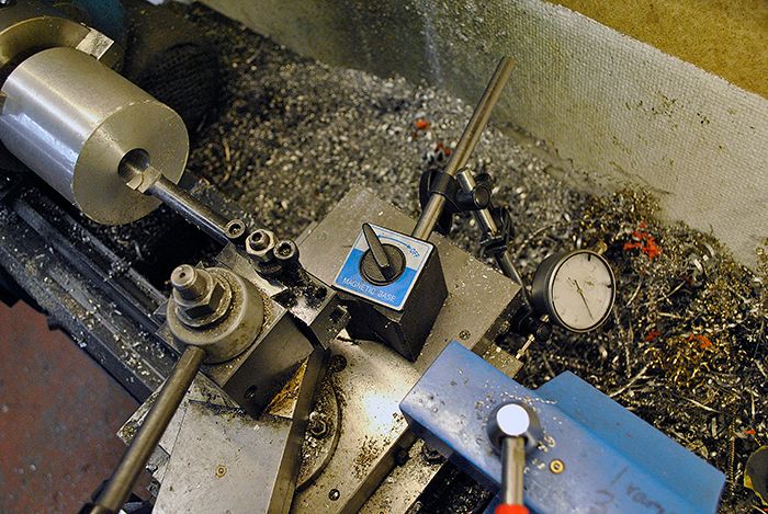 First off was to turn the journal bearing seats. 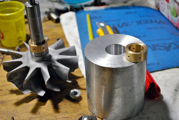 With the seats cut to the correct radial clearance I fit the shaft tunnel to the rotary table and drilled and tapped the compressor side bolt circle. 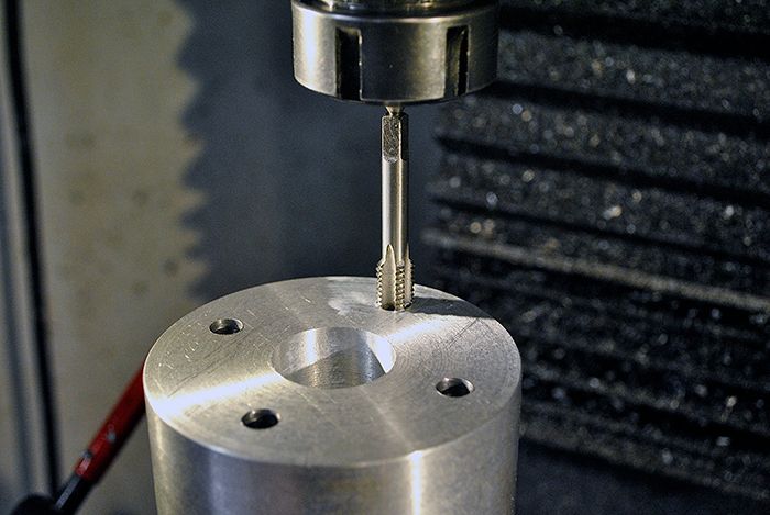 With that done I fastened the diffusor plate to the shaft tunnel and milled a flat surface so I can fit it the other way when I make the thrust bearing seat. Great to have a project of this magnitude going so I have something to occupy my mind with while waiting for the race season to arrive!  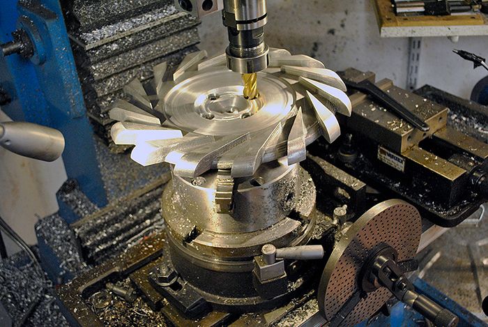 Cheers! /Anders |
|
|
|
Post by smithy1 on Feb 3, 2016 16:49:02 GMT -5
Hi Anders,
Nice work....please can you tell me what radial clearance you're using for the journal bearings??
Cheers,
Smithy.
|
|
|
|
Post by racket on Feb 3, 2016 17:55:54 GMT -5
Hi Smithy
The TV94 data sheet has
Bearing housing bore.......... 1.2045"- 1.2050" , 30.5940 mm- 30.6070 mm
Bearing OD ................... 1.1992" min to 1.1997" max , 30.4597 mm min to 30.4724 mm max
Bearing ID.....................0.8498" min to 0.8503"max , 21.5849 mm min to 21.5976 mm max
Shaft Journal .................0.8480" min to 0.8484" max , 21.5390 mm min to 21.5490 mm max
Radial Diametric Clearance ....0.0030" to 0.0070" ( 1.5 to 3.5 thou radial gap around bearing , pretty rattly), 0.0800 mm to 0.1800 mm
Journal to Bearing Bore 1.4 thou min to 2.3 thou max diametric ( 0.7 to 1.15 thou max radial gap , about half exterior clearance)
And axial end play ( thrust bearing clearance) 0.0030" min to 0.0100" max , though the turbo repair guy likes to err on the high side ~0.0080" and said he often laps his thrust bearing rear side down a few thou to achieve that clearance .
Heh heh , there ain't no fancy fits , easy to machine to those sort of clearance ranges :-)
Cheers
John
|
|
|
|
Post by smithy1 on Feb 3, 2016 18:49:44 GMT -5
Thanks John..Hmmm, methinks hot thin oil may struggle a bit then..? Hence the need for plenty of flow volume and pressure to keep them happy. I must get hold of a bearing repair kit for the 6041 soon...just in case..!
Cheers,
Smithy.
|
|
|
|
Post by racket on Feb 3, 2016 20:17:53 GMT -5
Hi Smithy
LOL, the 6041 shouldn't need bearings for at least another 10,000 hours , Garrett had 3 year/300,000 mile durability on their big truck turbos 25 years ago ;-)
A 6041 turbo on a big genset diesel engine would do nearly 9,000 hours in a year..............heh heh , you've probably barely worked up a shine on bits by now, she's "heavy duty" .
Yep , lotsa flow is the key , enough to keep 50 psi at the turbo oil inlet port , everything just spins around in a pool of oil , you should have plenty .
Cheers
John
|
|
|
|
Post by Johansson on Feb 7, 2016 13:55:49 GMT -5
I hope you can stand to watch closeup pics of metal parts, because there will be heaps of them in this thread from now on.  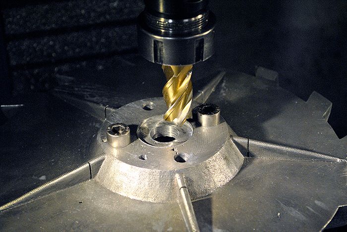 I´ve fitted a pair of dowels between the diffusor plate and the shaft tunnel to keep them perfectly centered, on the JU-01 engine I originally used the M10 bolts as alignment and that caused a major breakdown when the piston ring seal on the compressor spacer rubbed against its seat and jammed. 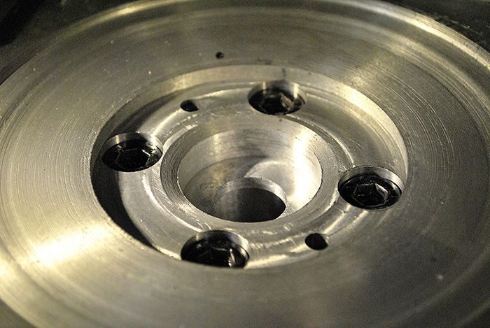 Here I am making the compressor spacer seat in SS2348 stainless, a very pleasant alloy to work with. 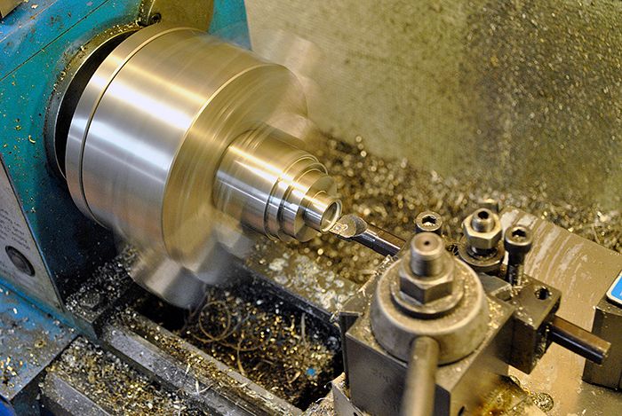 Here the thrust washer is seated in the diffusor plate, it was a bit tricky to get it right in the mill but thanks to the dowels I could remove the parts and measure the depth between each cut. It would probably have been a bit easier if I had made up detailed drawings of the part instead of just winging it, but where is the fun in that?  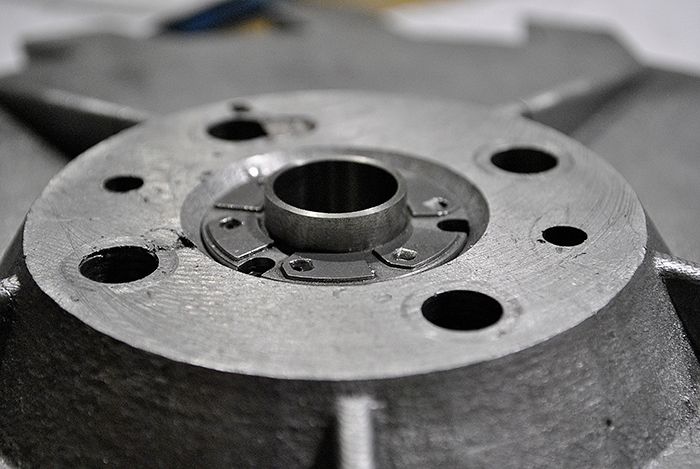 Here you can see the other side of the diffusor plate with the stainless insert seat fitted, I have more work to do before I can fit the compressor spacer and bolt it to the diffusor plate. It will also be part of the oil channel to the thrust bearing so I need to seal it properly to avoid oil leakage. 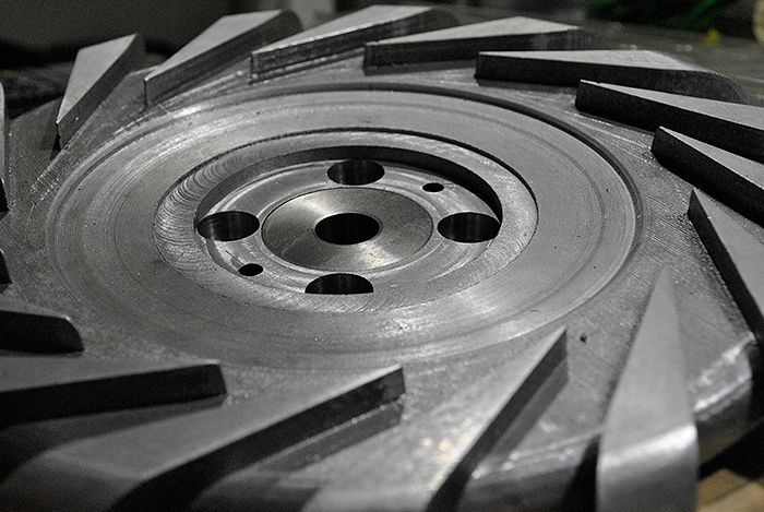 Cheers! /Anders |
|
|
|
Post by racket on Feb 7, 2016 15:45:27 GMT -5
Hi Anders
Coming together nicely :-)
Yes , a very tricky part to get right .
Are you going to screw through the stainless insert into the thrust bearing to hold the two bits in place ?
Cheers
John
|
|
|
|
Post by Johansson on Feb 7, 2016 16:02:08 GMT -5
Hi Anders Coming together nicely :-) Yes , a very tricky part to get right . Are you going to screw through the stainless insert into the thrust bearing to hold the two bits in place ? Cheers John Hi John, Thanks, yes it is absolutely the most tricky part to make. One mistake and the whole casting is scrap. The plan is to fit screws from the thrust bearing side and into the insert. I am not sure if I dare to cut M3 threads in the stainless insert though. Drilling it through and use countersunk nyloc nuts would be a safer choice, I really don´t want to break a tap in the insert.  Cheers! /Anders |
|
|
|
Post by racket on Feb 7, 2016 18:00:35 GMT -5
Hi Anders
For the securing screws , I come through from the front and tap the 3 thrust bearing "rivet" holes to 3 mm , the thrust bearing material is reasonably "soft ??" to tap as I think it has a percentage of "lead" in its composition.
With the thrust bearing and insert in position I drill through using one of the thrust bearing holes as a guide ,then I remove the thrust bearing , then I turn over the assembly and drill through from the front with a 3 mm drill , after cleaning up hole edges I replace the thrust bearing and using the drill hole as a guide I tap the thrust bearing hole .
By inserting a 3 mm screw and locking the bits in place, I then drill the other two holes , drilling from the thrust bearing , then removing thrust bearing , opening up the 2 holes to 3 mm , replacing the thrust bearing after making sure theres no rough hole edges to stop the thrust bearing sitting nice and square in its pocket , and then tapping the other 2 thrust bearing holes .
Because my stainless insert is in a pocket , the 3 mm stainless countersunk socket headed screw heads gently contact the sides of the pocket , I'm able to use a centre punch to raise a bit of the alloy pocket to stop the screws backing out on final assembly .
With some Loctite hydraulic thread seal on all the bits to prevent leaks , and a good "blow out" with compressed air after sufficient time for the sealant to set , it seems to work OK
Cheers
John
|
|
|
|
Post by Johansson on Feb 9, 2016 14:46:43 GMT -5
Thanks for the explanation John, I´ve reconsidered and decided to use separate screws for the thrust washer and another set that holds the insert in place. That way I can torque down the insert properly without risking to damage the soft thrust washer threads. Last night I spent a couple of hours on the engine after watching an episode of Game of Thrones with my feancee, I´ve found that the only way to get the image of stiff necked dwarfs and dangling titties out of my head is building gas turbines while listening to thrash metal.  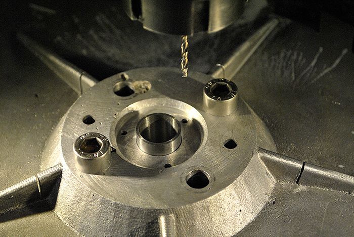 In the picture above I am drilling the screw holes for the thrust washer, then I continued turning the stanless insert to accept the compressor spacer and make room for the rear of the compressor wheel. 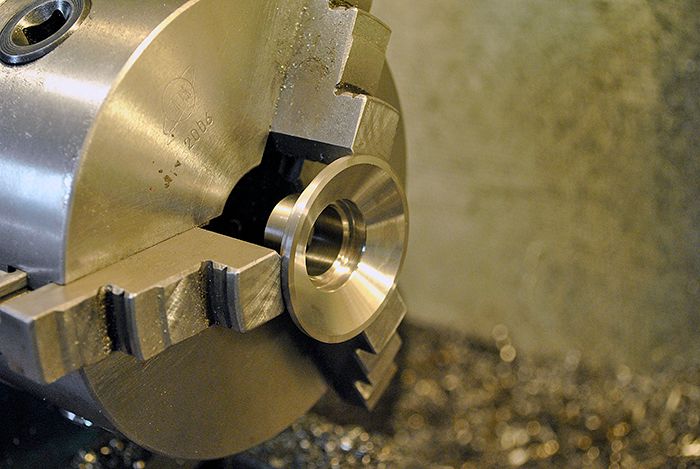 All of the thrust bearing parts together on the table before test fitting. 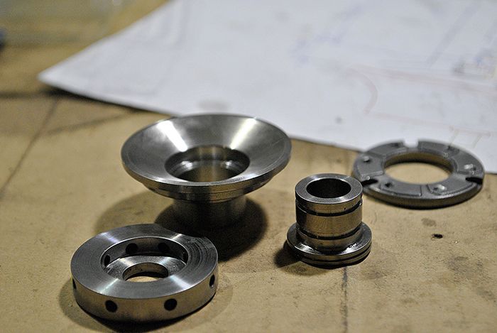 A rear view of the thrust bearing seat with the compressor spacer fitted inside the insert. A couple of shallow pores from the casting can also be seen, luckily they do no harm where they are. 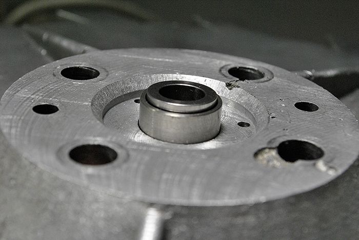 The front end, I will mill four pockets where securing screws for the insert will be placed. It is a bit difficult to explain but I think you will get the idea when I can show some pics of it. 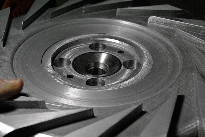 Things are coming together at a decent pace so far, next up is to secure the thrust washer and insert and drill the oil passage to the pocket between the insert and washer. Cheers! /Anders Tjo!  |
|
|
|
Post by Johansson on Feb 12, 2016 11:37:42 GMT -5
Today I was free from work so I spent the morning in the workshop instead, much progress was made since I remember most of the steps from the old JU-01 engine build. To seal the oil passage I will use a silicone o-ring, here I am turning a stainless sleeve that will keep the o-ring from collapsing when the engine is bolted together. 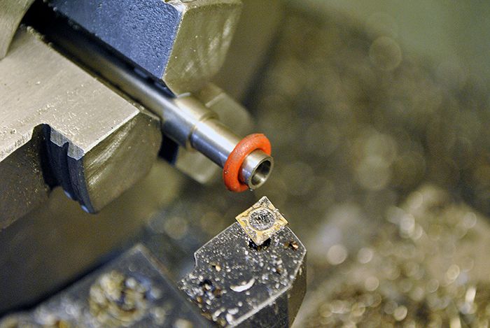 Here I am drilling an 8mm deep hole for the oil passage, after that I used the Dremel to mill a channel into the oil pocket behind the stainless insert and drilled three holes that will let oil in to the back of the thrust washer. I forgot to take any pics of that unfortunately. 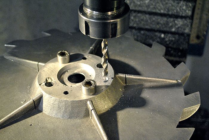 With the shaft tunnel still indexed on the rotary table I drilled the other side of the oil passage and milled a seat for the o-ring. 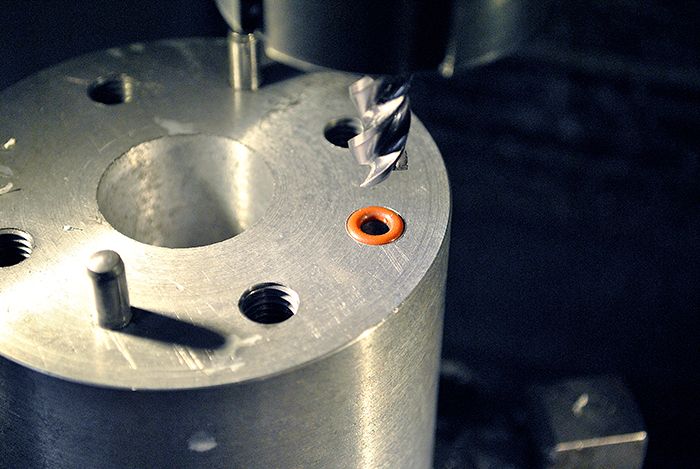 Here I have milled the rear axial washer seat, a delicate job since the depth of the seat determines the axial clearance in the thrust bearing. I have also milled a pocket for the oil to drain down into after passing through the bearing, a channel that connects to the journal bearing drain will be drilled later. A spring pin has also been fitted to keep the rear washer from rotating. 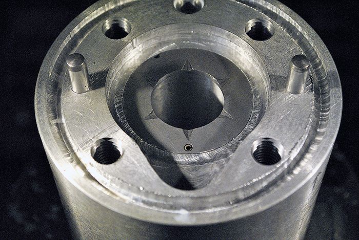 Threading the shaft tunnel for the four M3 screws that will hold the rear washer in place, I did the same modification to the JU-01 engine and found it very easy compared to machining up a sleeve of exact length that will hold the washer in place. 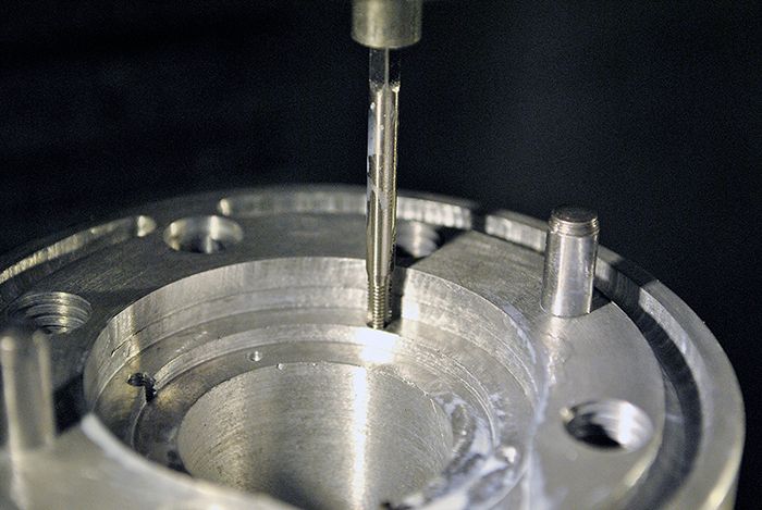 Tightened down properly! You can also see the outer groove for a 5mm silicone rope that will seal the parting surface from oil and air leakage. 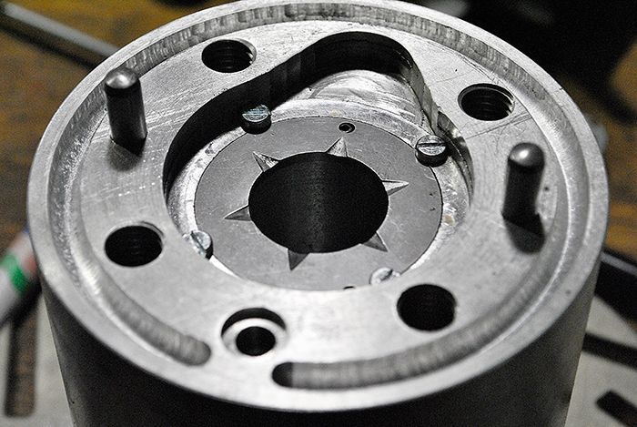 The last job before the thrust bearing is finished, fastening the thrust washer and piston ring seal insert to the diffusor plate. Here I am cutting the M3 threads in the stainless insert. 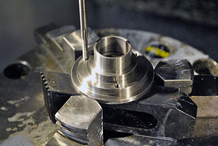 I´ve decided to use long M3 screws that is fitted from the thrust washer side, goes through the diffusor plate and screws into the insert. This way I can torque together the parts properly without risking to damage the threads if they were cut in the soft thrust washer. 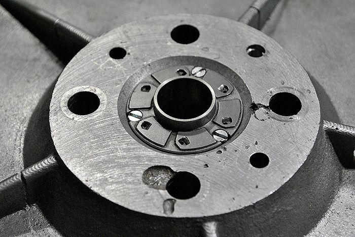 The business end of the same part, the screws need to be shortened down a bit as you can see. 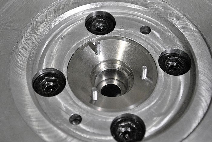 An overview of the assembly table, it might look a bit crowded to a Feng Shui minded person but I can assure you that this is clean compared to the other flat surfaces in the workshop.  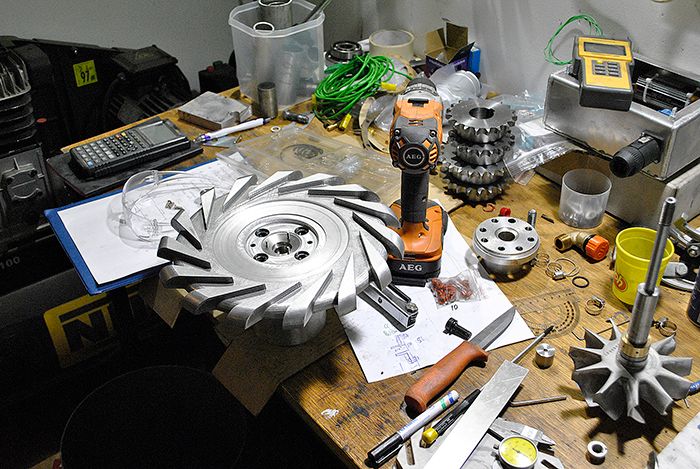 Cheers! /Anders |
|
Chuks
Senior Member
  
Joined: August 2015
Posts: 498 
|
Post by Chuks on Feb 12, 2016 12:19:01 GMT -5
nice job.... wish i can get use to bearing arrangement someday
|
|
|
|
Post by Johansson on Feb 12, 2016 14:19:58 GMT -5
nice job.... wish i can get use to bearing arrangement someday Google is your best friend when you want to learn something like this, here is a cutaway from a normal turbocharger that shows the journal bearing arrangement.  |
|
Chuks
Senior Member
  
Joined: August 2015
Posts: 498 
|
Post by Chuks on Feb 12, 2016 18:51:11 GMT -5
thank for the tips, putting a ballbearing together means lots and lots of bushing that never stays at a place.
|
|