miuge
Veteran Member
  
Joined: March 2014
Posts: 200 
|
Post by miuge on Jan 16, 2020 10:06:26 GMT -5
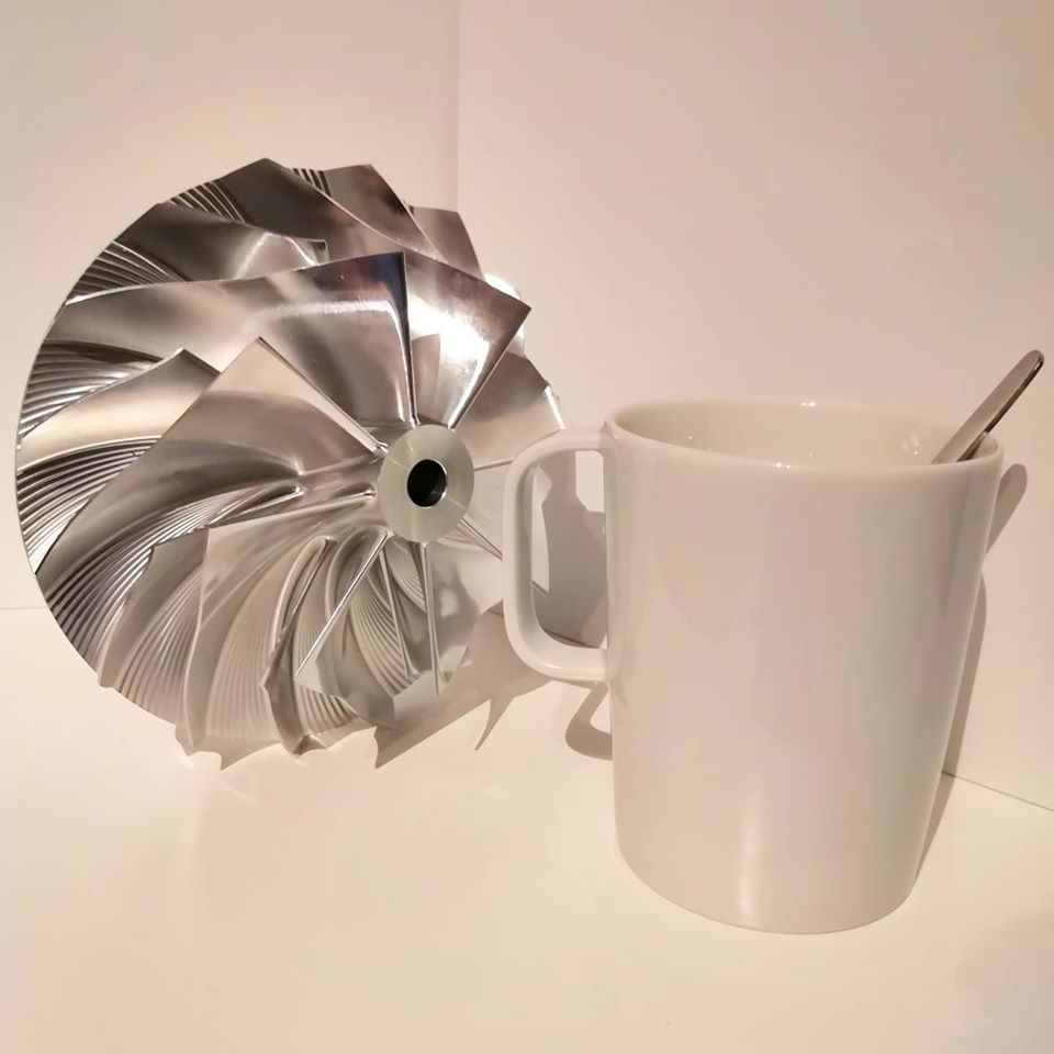
I reached my earlier email contacts and got my hands on this X856 compressor wheel, it will be mated with a 112/129mm HX82 turbine shaft, also bought a rebuild kit including bearings for the shaft:  |
|
|
|
Post by racket on Jan 16, 2020 15:36:35 GMT -5
Hi Miuge
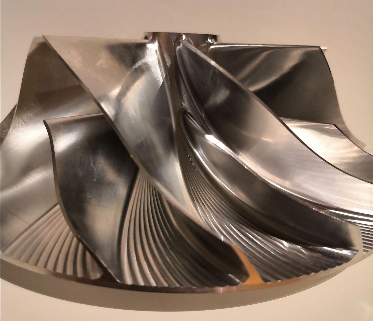
The X856 has the larger exducer tip height and smaller superback than the X846 wheel that Anders is using , so we can assume its made for a "lower" Pressure Ratio , its closer to Andy M's X858 wheel with its 11.8 mm tip height , they're beautiful bits of alloy :-)
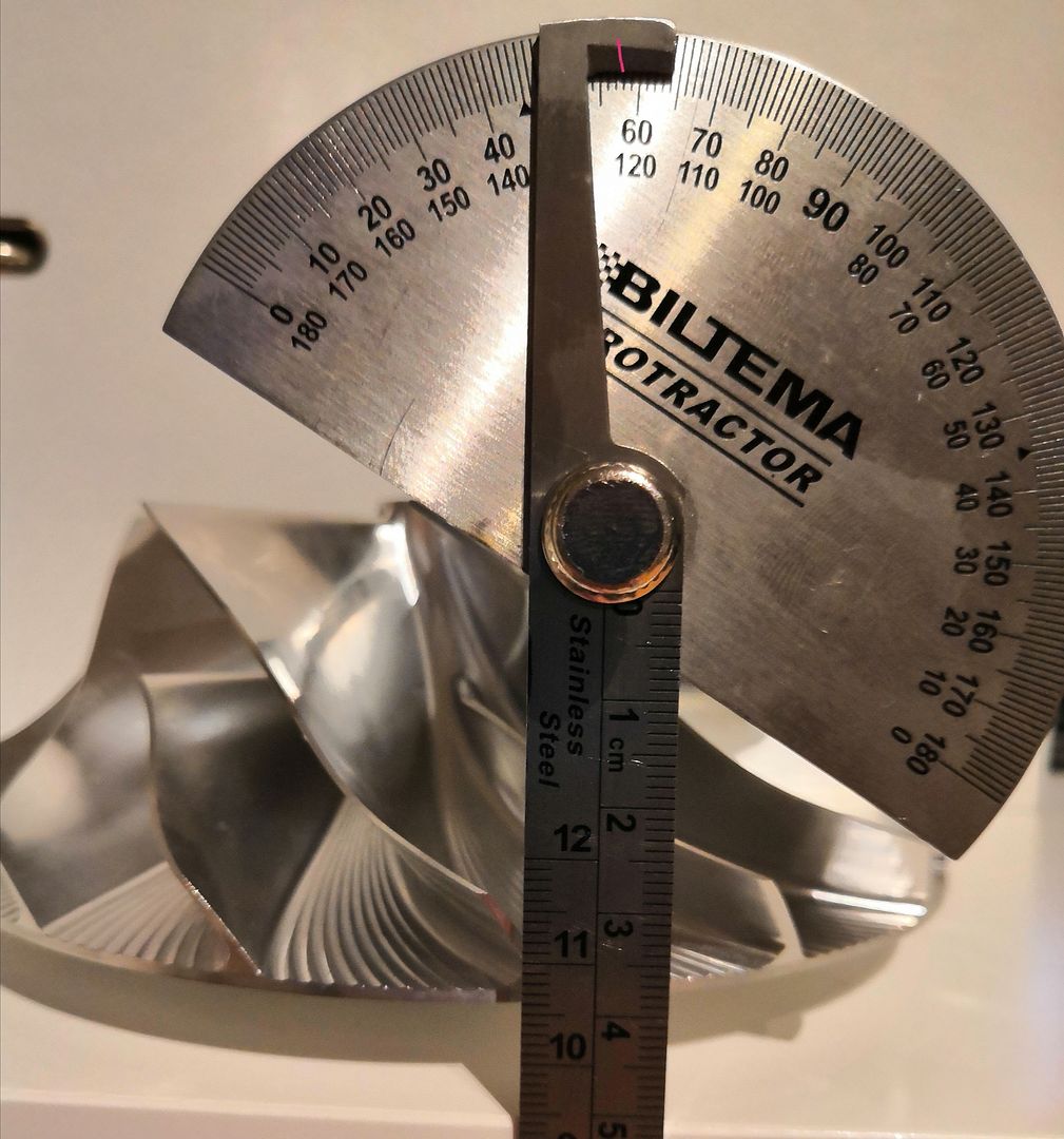
You might need to check the inducer tip angle to see if its been designed for high inlet air speeds , the X846 is at ~24 degrees whereas the higher airflow ones are up ~30 degrees or more , you'll need to determine what the wheel was designed for before thinking about the rest of the comp and turb stages , some reverse engineering required .
I'm looking forward to your build
Cheers
John
|
|
miuge
Veteran Member
  
Joined: March 2014
Posts: 200 
|
Post by miuge on Jan 16, 2020 18:39:51 GMT -5
I had various radial compressor documents and data collected, even some calculations made when I was last time delved into the topic, but now all that's missing, probably did too thorough cleanup for my computer... For some rational reason, I think, I ended up with the higher tip height and especially X856. On page 4 I found discussion where Chris (finiteparts) stated that higher tip height B would oppositely refer to a higher PR? John, are these pics any help determining the inducer tip angle? Got a reading 57-58deg from axial, equals 33-32deg?   |
|
|
|
Post by racket on Jan 16, 2020 19:20:22 GMT -5
Hi Miuge
Yep she's a high flow unit with that "steep" 32 degree inducer angle, thats good , it'll help with the outflow angles with that larger exducer height :-)
LOL, I have all my calcs written in books , my computor skills aren't good enough to trust them to cyber space .
What are your plans for the engine ,.......... thrust or freepower ??
Cheers
John
|
|
miuge
Veteran Member
  
Joined: March 2014
Posts: 200 
|
Post by miuge on Jan 17, 2020 9:41:29 GMT -5
Hi John,
That's good news. Eventually the gas producer should be attached to a freepower unit and then a bike frame would be built around it.
I'm not sure if my notebooks are any better safe, been moving around and always cleaned up storages/archives that never seem so useful until you've got rid of them ...
|
|
|
|
Post by Johansson on Jan 17, 2020 14:30:16 GMT -5
That would be awesome! It will be like a jet-powered version of "Finnkampen".  |
|
miuge
Veteran Member
  
Joined: March 2014
Posts: 200 
|
Post by miuge on Mar 29, 2020 5:34:05 GMT -5
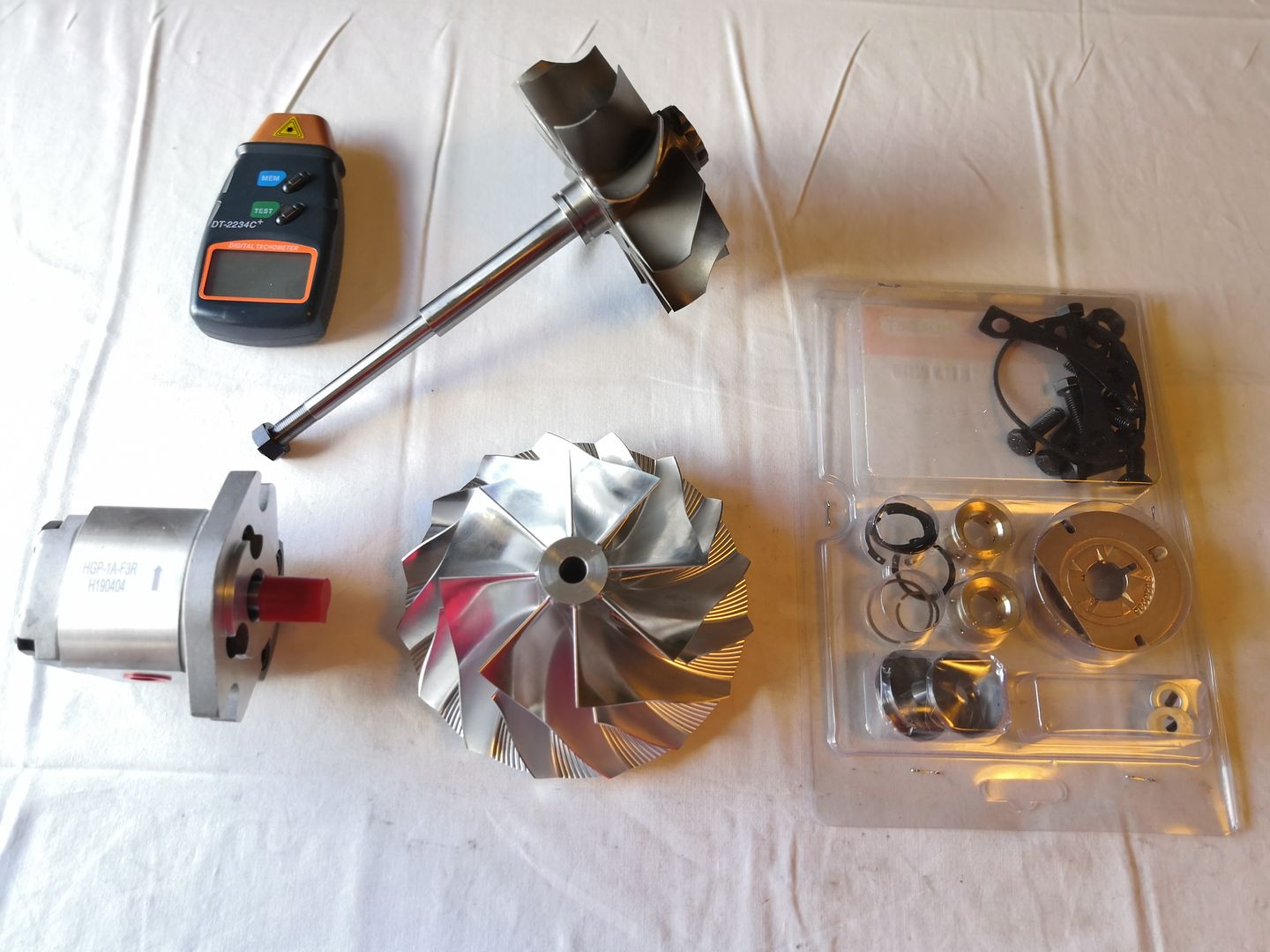
Have been acquiring few of the most critical components for the build: -X856 comp wheel, 106*152*156*11.8mm -HX82 turb wheel, 112*129*19mm -HX82 rebuild kit -HGP-1A-F3 gear pump for oil system, 3cc/rpm -Digital tachometer  |
|
|
|
Post by racket on Mar 29, 2020 16:54:39 GMT -5
Nice bits :-)
Let the build begin
|
|
miuge
Veteran Member
  
Joined: March 2014
Posts: 200 
|
Post by miuge on Sept 21, 2020 15:44:33 GMT -5
Hello people, It's been a few quiet months here meanwhile we have set up the new shop and learned a lot about CNC machining basics. Turning parts seem pretty straightforward with simple milling operations, this is what we've been doing last couple of months daily on repeat. Now I'd love to try some more complex milling operations and what I've been thinking as a good practise is a compressor diffuser, a nice symmetrical part within the capabilities of our CAM software. The question is, as our time is limited with the actual workpieces, could someone help with the math part of the project? We are not doing a commercial turbine, just a one-off hobby engine utilizing the machinery at the workplace. This could be another great showcase for what JATO forums is capable of  The parts I've already acquired are: -X856 comp wheel, 106*152*156*11.8mm
-HX82 turb wheel, 112*129*19mm
Eventually I'd like to run the engine in powerturbine configuration.  |
|
|
|
Post by racket on Sept 21, 2020 16:40:09 GMT -5
Hi Miuge
You could use Andy M's diffuser design , you both have the same tip height , exducer diameter , just a 4 mm smaller inducer in your case which really won't make much difference to the flow conditions, its <10% difference in potential mass flows, I designed for 3 lbs/sec for Andy and you'll be capable of at least 2.75 lbs/sec .
OOPS , just checked your Thread and the inducer tip is at 32 degrees , so a "high flow" design , so maybe similar mass flow potential to Andies comp.
Have a chat to Andy :-)
Cheers
John
|
|
miuge
Veteran Member
  
Joined: March 2014
Posts: 200 
|
Post by miuge on Sept 23, 2020 14:28:04 GMT -5
Hi John,
Thanks for the tip, that's good to know. I've reached Andy and he is willing to share his information, am very thankful for that! Will be sharing our outcome as we proceed.
|
|
miuge
Veteran Member
  
Joined: March 2014
Posts: 200 
|
Post by miuge on Sept 29, 2020 16:17:42 GMT -5
Thanks to Andy I was able to make the first rough sketch of the comp diffuser, same diameters/areas/angles were used. What I'm trying is to smooth out the passages slightly with gentle radiuses. Passage entries and leading edges obviously need more work in my design, hopefully after few long nights things will clear. I also need to check whether our CAM software can or cannot work around this kind of shapes. _diffuser_test_2(1).JPG?width=1920&height=1080&fit=bounds)
_diffuser_test_1.JPG?width=1920&height=1080&fit=bounds) |
|
miuge
Veteran Member
  
Joined: March 2014
Posts: 200 
|
Post by miuge on Oct 8, 2020 12:33:10 GMT -5
Looks like we could make the diffuser as planned with the software we got. I'd like to run a scaled down test part on our machine first, then we could move on to real design process.
|
|
|
|
Post by wannabebuilderuk on Oct 8, 2020 13:58:35 GMT -5
I could watch that for hours it's rather satisfying... Wonder if you scaled everything down could you make a mini engine to go with its big brother ha
|
|
|
|
Post by stoffe64 on Jan 15, 2023 7:06:46 GMT -5
Any news on this one Mikko?
|
|