CH3NO2
Senior Member

Joined: March 2017
Posts: 455 
|
Post by CH3NO2 on Apr 3, 2017 14:42:51 GMT -5
All of you guys. You're doing awesome crazy stuff. Keep up the great work.  I like this forum. The average IQ of people here is light years ahead of the rest of the net. I can actually learn something here.  |
|
|
|
Post by olovselander on Apr 5, 2017 16:05:14 GMT -5
We´re making some small steps in the right direction on the chassis. I´ve made the cross bracings in the sides this evening. A pair of 25mm end mills showed up in the mailbox today. The hole saws do work ok but the end mills i think are better, will last longer at least. 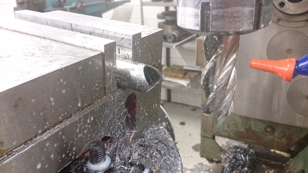 It takes some time and thinking to get all angles and lengths right but when it´s time to weld it´s all worth it! 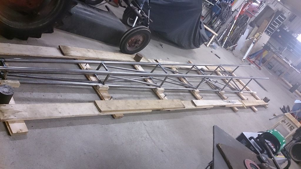 I also had to make a test run! No record to night though.. 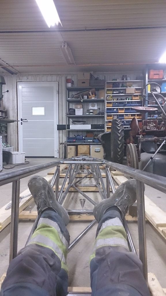 Good night! |
|
|
|
Post by racket on Apr 5, 2017 16:19:58 GMT -5
Hi Olov
You fit just right , it'll be a much more comfortable ride than the kick .
The chassis is looking great , a very professional job :-)
Cheers
John
|
|
|
|
Post by smithy1 on Apr 5, 2017 21:59:44 GMT -5
Olov....very nice work indeed...
I've really got to get over there for the "Speedweek" one year, even if it's just to watch.....John...we must organize something.
Smithy.
|
|
|
|
Post by stoffe64 on Apr 6, 2017 3:55:00 GMT -5
Yes, please do Come over here to sweden, it would be so fun to actually meet you guys, why not bring your cart Brett??
That would be interesting!!
|
|
|
|
Post by Johansson on May 5, 2017 15:46:05 GMT -5
After doing this and that waiting for material and inspiration I spent an evening on the turbofan build. 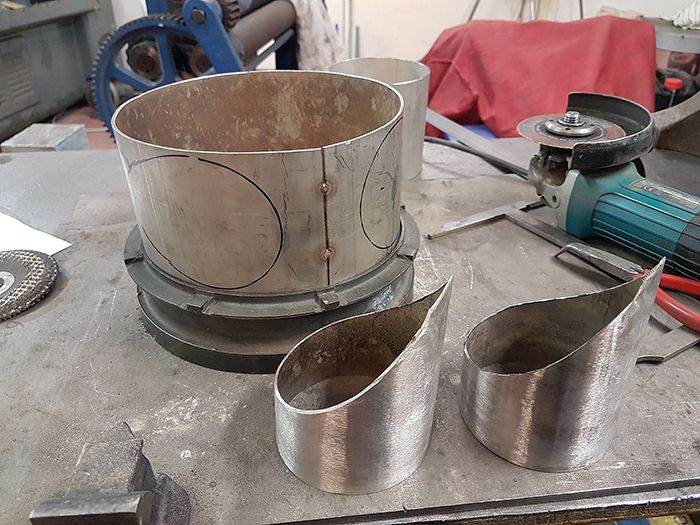 It feels wort of wrong to build the exhaust manifold this way, I would like to keep nice radiuses everywhere for optimal flow and so on but to keep the shaft length short and a generous air inflow area for the fan I need to compromise with the exhaust manifold. Luckily the gas producers have a bit of overcapacity so we should still be able to run the turbofan up to its max of 33.000rpm, if not I´ll just have to redesign the manifold later. 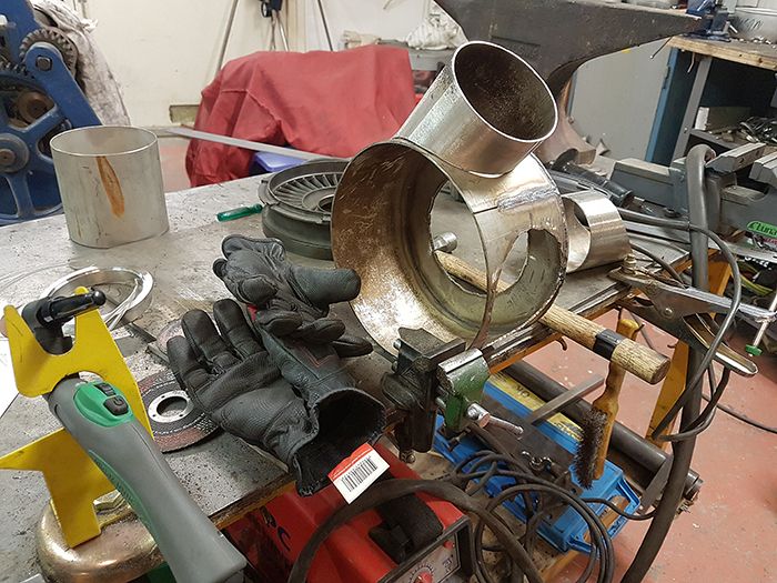 After a couple of hours of plasma cutting, tig welding and coffee drinking I had a tacked together manifold on the table. Here is the power turbine NGV that it eventually will be welded to. 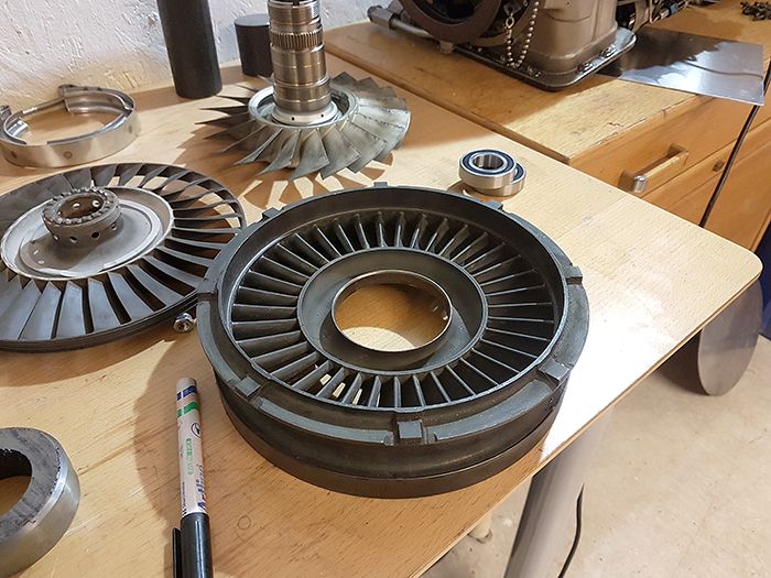 And here it has the manifold fitted to it. 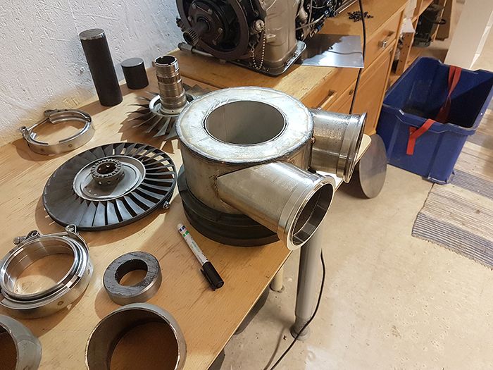 I will shorten the pipes holding the V-band flanges a bit before welding everything together, to them there will be 3.5" stainless bends and a length of flexible exhaust duct leading from the gas producers placed ahead and below the turbofan in the chassis. 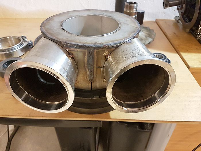 I´ll add the drawing of the engine setup again in case someone wonders what I am doing. 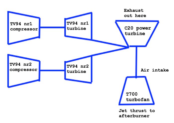 Cheers! /Anders |
|
Sweetenough
Veteran Member
Joined: April 2016
Posts: 121
|
Post by Sweetenough on May 5, 2017 17:29:20 GMT -5
Hi Anders,
Impressive work as usual!
I always get amazed what you can accomplish in a few hours in the workshop!
Looking forward to follow the build!
|
|
|
|
Post by racket on May 5, 2017 19:44:33 GMT -5
Hi Anders
Yep , it was always going to be a difficult job getting the gases in from the two turbos , perhaps provide a nice diffusing exhaust on the freepower to compensate for the inlet side compromises .
I'd imagine it wasn't possible due to turbo installation constraints to have a pair of "tangential" inlet on opposing sides of the freepower inlet duct to promote "pre swirl" upstream of the NGV.
Cheers
John
|
|
|
|
Post by Johansson on May 6, 2017 0:06:26 GMT -5
Hi Anders, Impressive work as usual! I always get amazed what you can accomplish in a few hours in the workshop! Looking forward to follow the build! Hi Thomas, Thanks a lot! The main time thief when constructing something is "thinking twice", "measuring again to make sure" and other similar habits, my workshop style is best compared with a kid running headlong down a steep hill. Cheers! /Anders Hi Anders Yep , it was always going to be a difficult job getting the gases in from the two turbos , perhaps provide a nice diffusing exhaust on the freepower to compensate for the inlet side compromises . I'd imagine it wasn't possible due to turbo installation constraints to have a pair of "tangential" inlet on opposing sides of the freepower inlet duct to promote "pre swirl" upstream of the NGV. Cheers John Hi John, Unfortunately not, I fear that the ducting for a tangential entry would end up outside the ice yacht fairings which is a no-no.  Still, I spent an evening on this so if we find later that there is room for improvements I can easily blank off one inlet and fit it "the other way around" so the gasses circulate in the same direction. Cheers! /Anders |
|
ripcrow
Veteran Member
Joined: December 2015
Posts: 114
|
Post by ripcrow on May 6, 2017 0:12:24 GMT -5
This is madness. Watching with anticipation
|
|
Sweetenough
Veteran Member
Joined: April 2016
Posts: 121
|
Post by Sweetenough on May 6, 2017 1:49:00 GMT -5
Hi Anders, Impressive work as usual! I always get amazed what you can accomplish in a few hours in the workshop! Looking forward to follow the build! Hi Thomas, Thanks a lot! The main time thief when constructing something is "thinking twice", "measuring again to make sure" and other similar habits, my workshop style is best compared with a kid running headlong down a steep hill. Cheers! /Anders Hi Anders, Haha, will try to adopt your work shop stile! I do way to much "making sure" work. Kind Regards Thomas Hi Anders Yep , it was always going to be a difficult job getting the gases in from the two turbos , perhaps provide a nice diffusing exhaust on the freepower to compensate for the inlet side compromises . I'd imagine it wasn't possible due to turbo installation constraints to have a pair of "tangential" inlet on opposing sides of the freepower inlet duct to promote "pre swirl" upstream of the NGV. Cheers John Hi John, Unfortunately not, I fear that the ducting for a tangential entry would end up outside the ice yacht fairings which is a no-no. Still, I spent an evening on this so if we find later that there is room for improvements I can easily blank off one inlet and fit it "the other way around" so the gasses circulate in the same direction. Cheers! /Anders |
|
miuge
Veteran Member
Joined: March 2014
Posts: 199
|
Post by miuge on May 6, 2017 3:26:35 GMT -5
Hi Anders and Olov,
That's one interesting project for sure! Great fabrication level as always.
I was thinking the same about the exhaust manifold, just flip the other entry 180degree around it's axis, I'd imagine it would work better providing more even and swirled flow.
|
|
|
|
Post by racket on May 6, 2017 17:21:33 GMT -5
Hi Anders
Yep, I thought that might have been the reasoning behind the "compromise" .
As long as your interstage temps are still reasonable you'll know its not too much of a compromise , they shouldn't be any worse than when the A/B was previously fired up .
If you have less restrictive exhaust constraints you should be able to offset the inlet "compromises" to recoup any losses by gaining a tad more pressure drop by providing a good exhaust diffuser.
I'm looking forward to seeing how it all turns out .............LOL, I've drawn it up on paper a few times when doing the calcs , but its never the same as seeing the finished "metal" .
Cheers
John
|
|
|
|
Post by Johansson on May 9, 2017 16:43:38 GMT -5
It will be a tight fit to get everything packed in there in a service friendly manner, making a snakes nest of glowing hot exhaust ducting around the whole engine would make heat shielding a nightmare... We´ll try to make the exhaust as flow friendly as possible, as it will exit on top of the fairings I think that the air passing by at 200+km/h will help evacuating the exhaust gasses. 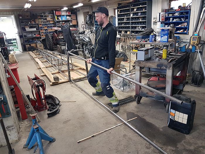 Olov and I was throwing ideas around after work today and couldn´t keep from giggling like two school girls, this will be a fun ride for sure! Cheers! /Anders |
|
|
|
Post by racket on May 9, 2017 17:17:46 GMT -5
Progressing steadily :-)
I rather envy you guys having someone to sit and "talk crap" with about a build, my shed is rather empty of laughter .
200 kph+ should be easily achieved , Olov might need some "aero controls" for steering and stability at its full potential ;-)
Cheers
John
|
|