|
|
Post by racket on May 12, 2017 20:46:21 GMT -5
Hi Ron
Thats interesting that even steel gets damaged over time , the leading edges are pretty thin being a transonic wheel , we'll keep an eye on them .
My thoughts are that the 600 ft/sec inflow airspeed will probably breakup the fuel flow fairly well before it even reaches the fan just from the shearing action between slow moving droplet and high speed air .
With the rate of fuel burn , total time for injection will probably be only a few minutes over its entire life ..............she'll be right, we have a spare :-)
Cheers
John
|
|
|
|
Post by Johansson on May 13, 2017 15:58:55 GMT -5
Since I am not very interested in the Eurovision finals I spent an hour modifying the fan instead.  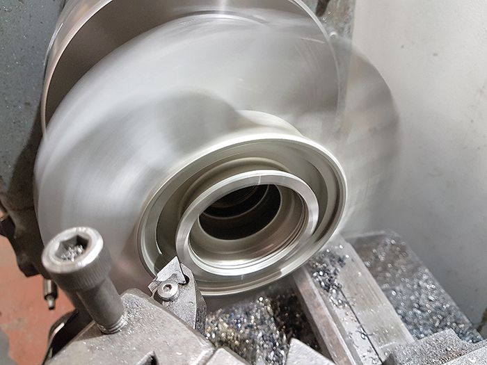 I removed the curvic coupling from the fan and cut the bore cylindrical so I can fit a centrum hub with a 25mm bore and a keyway slot. 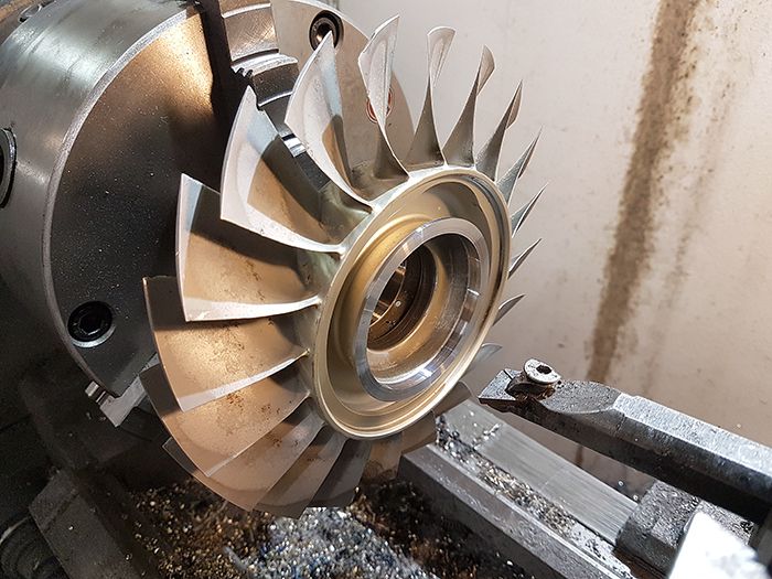 The angle grinder might not be everyones tool of choice when modifying gas turbine rotors, but it is darn handy. 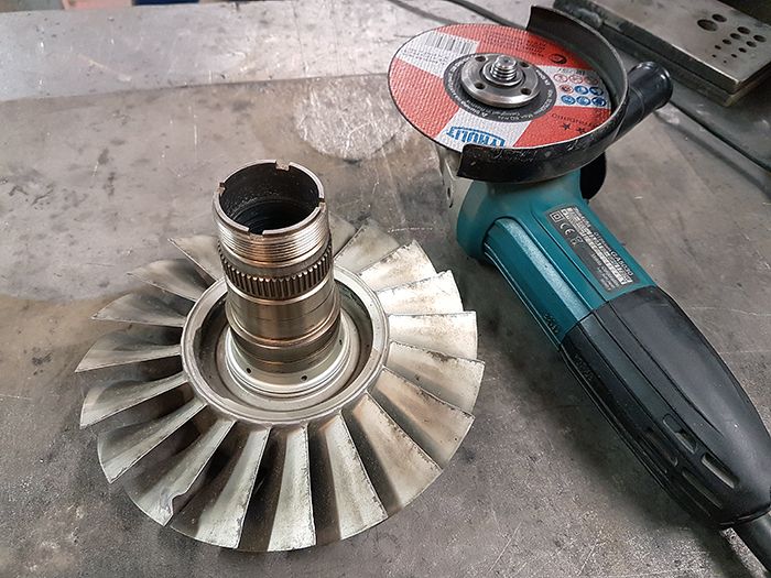 Almost there... 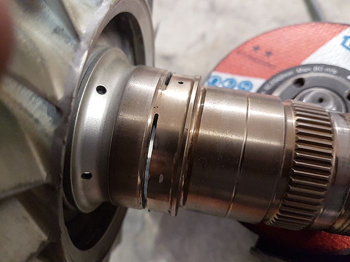 And it is done! When I have made and fitted the new fan hub I can mount the fan to a dummy shaft and true the angle grider cut edge in the lathe. 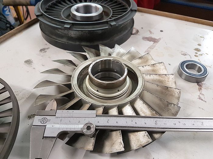 Cheers! /Anders |
|
|
|
Post by racket on May 13, 2017 17:28:48 GMT -5
Hi Anders
LOL.............but Sweden is currently coming third , one place ahead of Oz in the Eurovision points total ;-)
I love using my side grinder on those hard turbine bits ..............heh heh , precision grinding
You're putting the new chuck to good use ..............parts are looking great
Cheers
John
|
|
Deleted
Joined: January 1970
Posts: 0
|
Post by Deleted on May 14, 2017 2:33:29 GMT -5
Hi Anders
Real nice work :-)
Yes given the choice i would be in the work shop.....
All The Best
Andy
|
|
|
|
Post by Johansson on May 14, 2017 23:16:21 GMT -5
Thanks guys! The alternative to the angle grinder would have been a tricky fixture in the lathe with a big risk of wrecking a fan blade when the cut goes through the shaft wall. Doing it this way the job was safe as pudding! |
|
|
|
Post by Johansson on May 16, 2017 12:09:11 GMT -5
Last night I got a fair bit of work done, first I gave the rear bearing and turbine hub a press fit on the shaft. 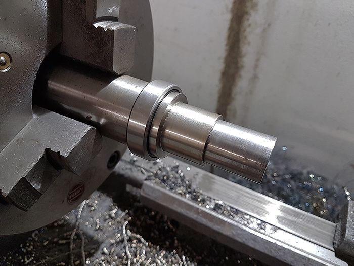 Left to do is to lock the turbine wheel on the shaft, but I think I got an idea how to do it. 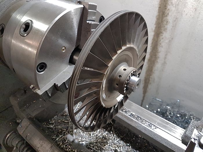 Here the shaft and turbine is assembled just to get an idea how much room I´ll have for the fan bellmouth. 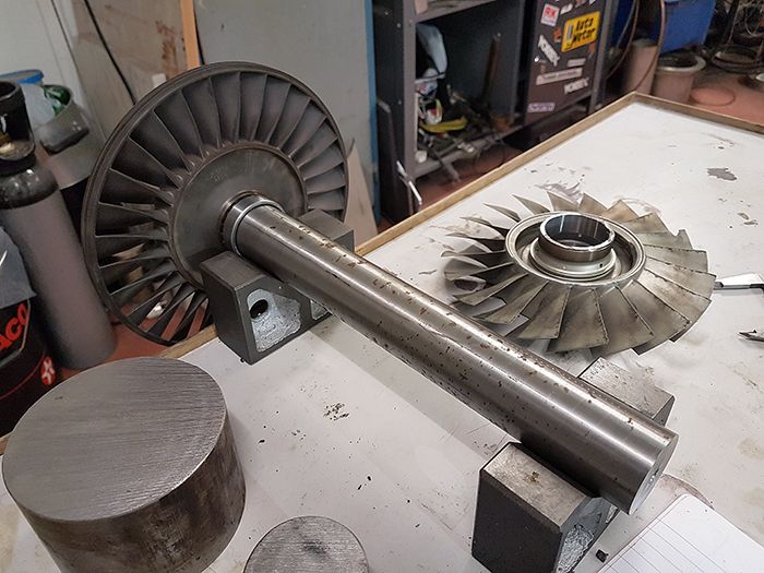 Next up was to turn the chunk of steel in the pic above into the fan hub. 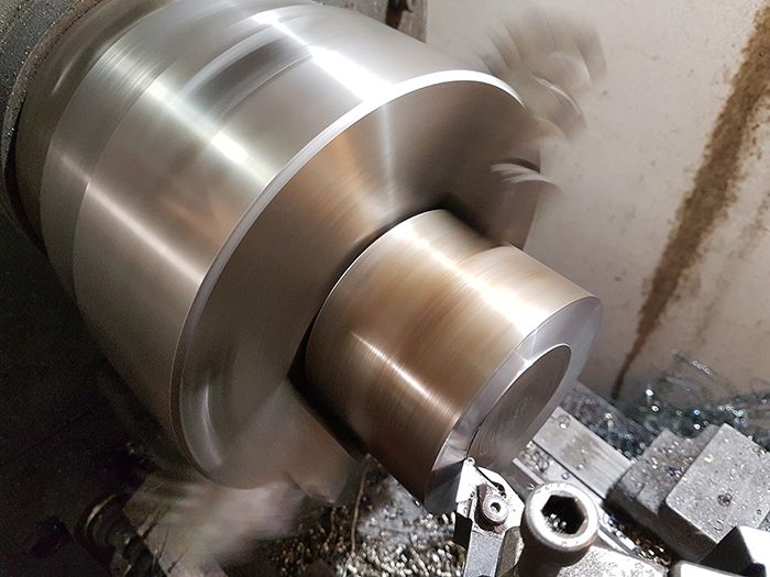 An hour or so later... 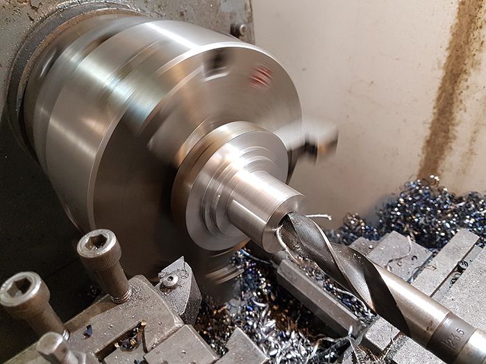 Here I am pressing a keyway in the hub bore. 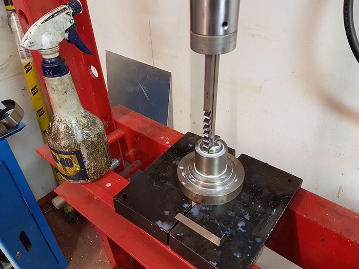 With that done I just had to remove the lathe chuck gripping area on the hub and turn a small pocket for the centrum screw, very important to think at least three steps ahead since I refuse to make detailed drawings in advance. 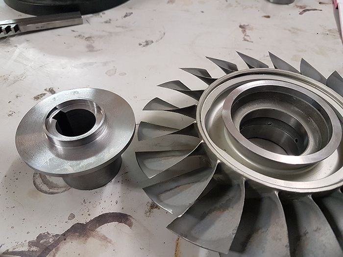 It can´t be seen in the pic above but there is a recess on the hub that has a tight press fit into the fan flange, I will also tig weld the edge around the flange to secure the hub in the fan for good. 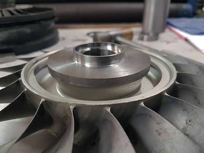 Finally a pic from above, the relatively basic workshop tools I have cannot give me 0.001mm precision for the parts but it doesen´t really matter since I will send the whole rotary assembly away to be dynamically balanced when it is finished. 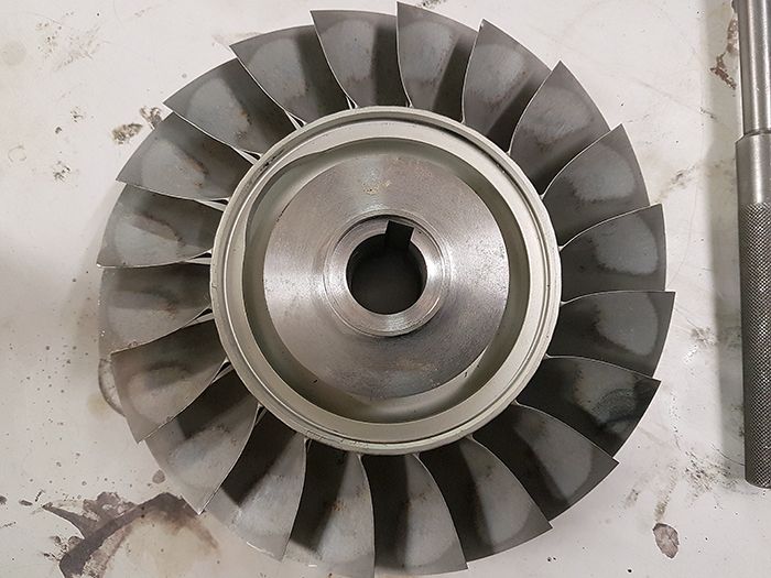 Cheers! /Anders |
|
|
|
Post by racket on May 16, 2017 17:05:26 GMT -5
Hi Anders
Some serious heavy duty work ..............nice :-)
I can see you're enjoying using the big lathe
Cheers
John
|
|
|
|
Post by Johansson on May 16, 2017 23:09:07 GMT -5
I sure am John, the big lathe is the best thing that has ever happened to my workshop. The smaller china lathe has surely proven its worth over the years but for jobs like these you really need something sturdier. Last night I spent half an hour removing the cut off stub on the fan, with the hub pressed in place I could use it to fit the fan to the lathe. 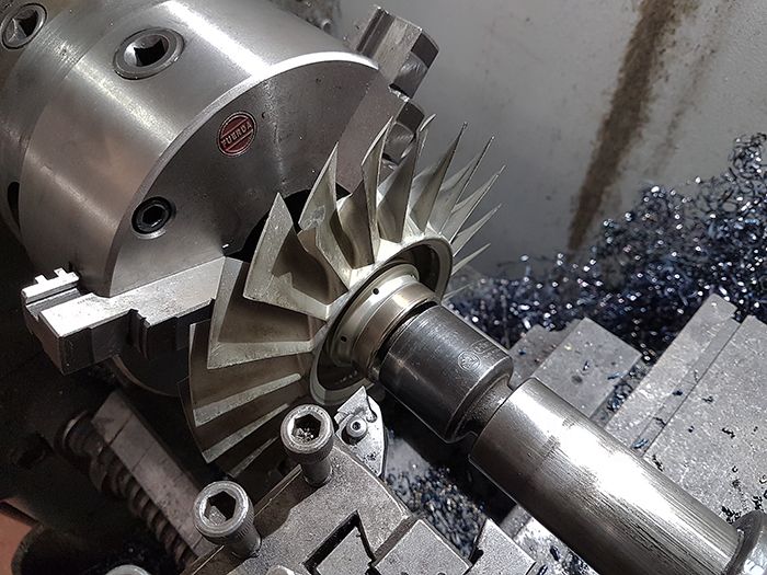 Since the hub is only press fitted in the fan I took very careful cuts so the fan wouldn´t come loose during the process. 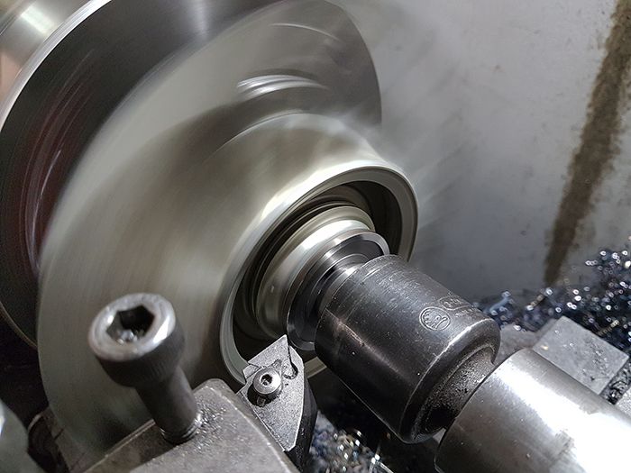 I test fitted the fan to the shaft afterwards to figure out what the fan side of the shaft will look like, no question marks arose so I have several evenings of work to do before I need to start thinking again! 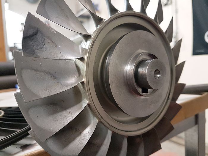 Cheers! /Anders |
|
|
|
Post by Johansson on May 18, 2017 15:50:38 GMT -5
Yesterday I spent my lunch hour grinding open the centrum of the curvic coupling on the turbine wheel, I had to make room for the bushing that locks the turbine wheel onto the shaft. 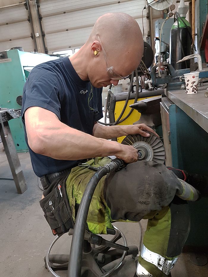 Later that day I turned down the turbine end of the shaft, the last tenth of a millimeter was ground with fine sand paper to get a snug fit for the bearing. 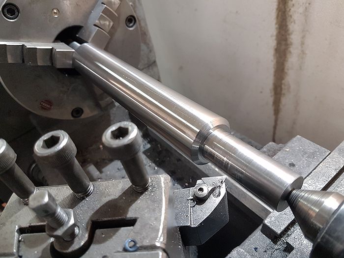 Checking if the shaft runs true after flipping it over, 3/100mm was measured at the end of the shaft which is about as good as it gets with the tools I have. 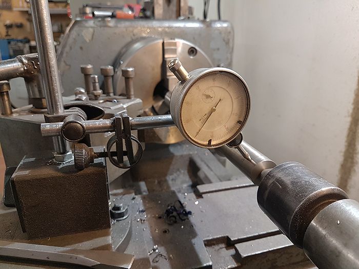 With the shaft done I started making the bushing for the turbine wheel. 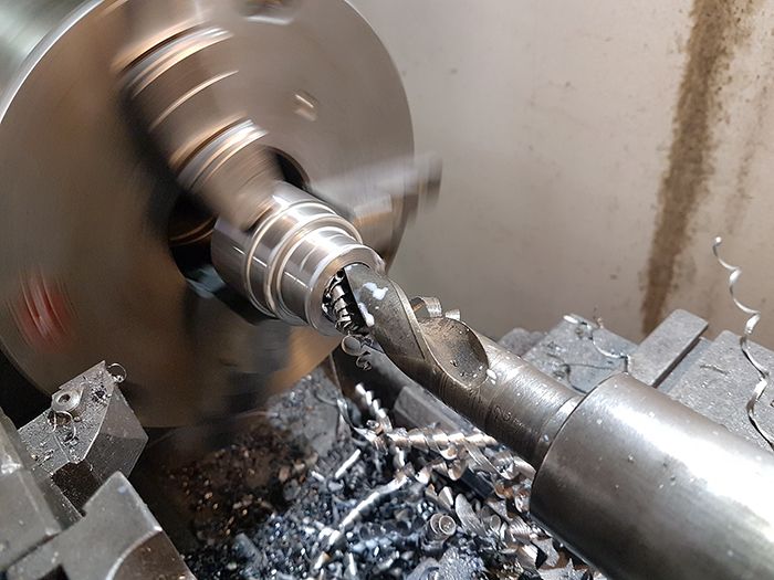 After turning and keyway broaching it looked like this, it still has the gripping surface left which will be removed later. 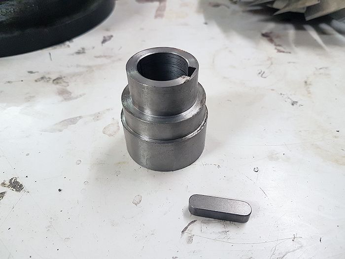 The bushing was then fitted to the rotary table in the mill to get its curvic coupling teeths machined. 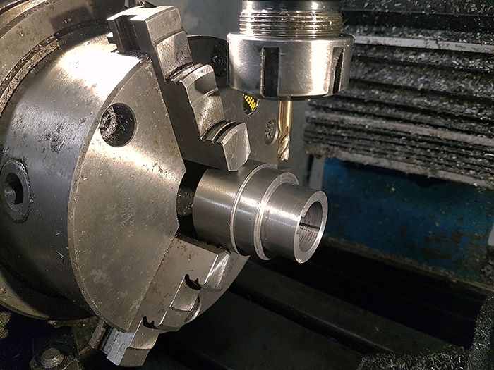 Finished!  With that done I could remove the gripping section in the lathe and trim the bushing to its final length. 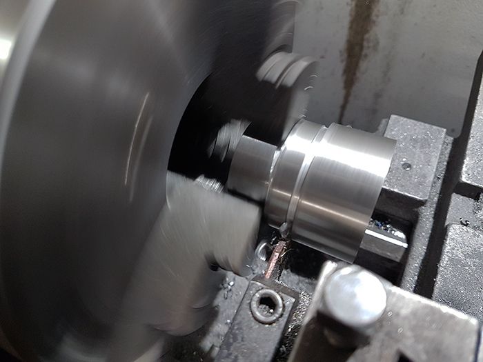 This looks like it could work. 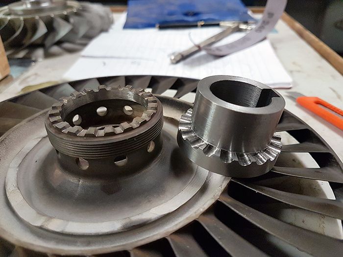 Hmm, something is missing in this picture... 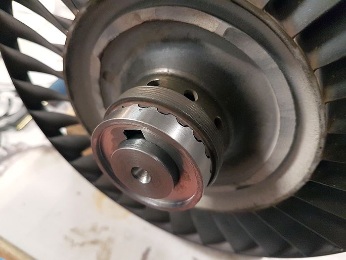 Oh yes, the keyway slot in the shaft! 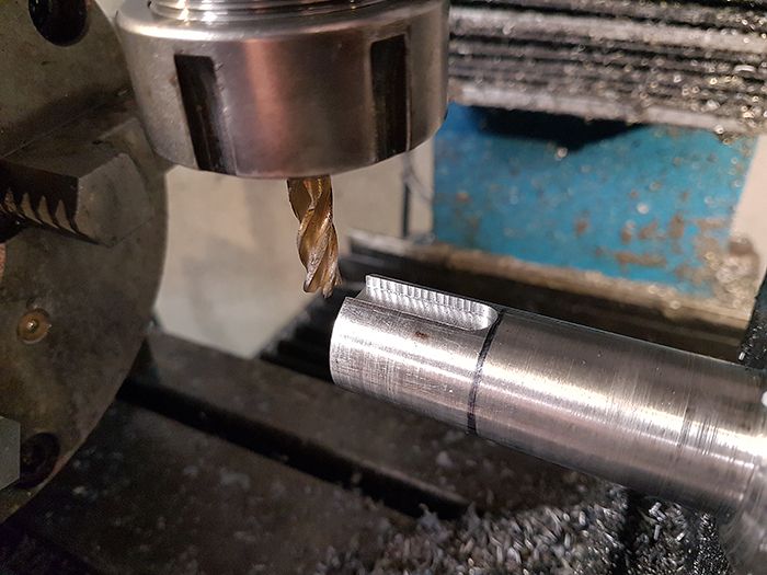 Now it looks better. 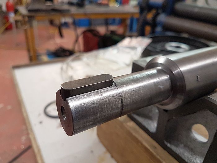 Finally the bushing was finished, all that is left now is to drill and thread the shaft for a locking insex screw and make a special washer in which the insex screw head can be wire locked. 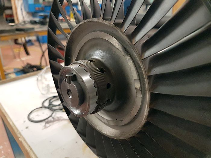 Cheers! /Anders |
|
|
|
Post by racket on May 18, 2017 17:45:05 GMT -5
Hi Anders
Excellent work as always :-)
I think you and Olov are in a race to see who finishes their builds first ;-)
Cheers
John
|
|
|
|
Post by pitciblackscotland on May 18, 2017 23:13:51 GMT -5
I sure am John, the big lathe is the best thing that has ever happened to my workshop. The smaller china lathe has surely proven its worth over the years but for jobs like these you really need something sturdier. Last night I spent half an hour removing the cut off stub on the fan, with the hub pressed in place I could use it to fit the fan to the lathe. Since the hub is only press fitted in the fan I took very careful cuts so the fan wouldn´t come loose during the process. I test fitted the fan to the shaft afterwards to figure out what the fan side of the shaft will look like, no question marks arose so I have several evenings of work to do before I need to start thinking again! Cheers! /Anders Same here,when i started using my Okuma lathe it's like holly shit!!! this is fantastic. Next will be a heavy duty milling machine and i I'm sure Anders you will get one as well in the future:) Cheers, Mark. |
|
|
|
Post by Johansson on May 19, 2017 2:40:29 GMT -5
Thanks John! I think I'll win that race, the fan build is a walk in the park compared to the chassis with suspended runners etc etc, we will join efforts on that later.
Mark, a real size mill would be nice to have. Unfortunately the mid sized ones are hard to come by, the ones that can be found in the local ads are the smaller china mills and the occational old 3000kg mill that would fill up my whole workshop...
|
|
|
|
Post by pitciblackscotland on May 19, 2017 3:26:13 GMT -5
Thanks John! I think I'll win that race, the fan build is a walk in the park compared to the chassis with suspended runners etc etc, we will join efforts on that later. Mark, a real size mill would be nice to have. Unfortunately the mid sized ones are hard to come by, the ones that can be found in the local ads are the smaller china mills and the occational old 3000kg mill that would fill up my whole workshop... Ah yes i know what you mean. Maybe when you sell the Viper and your china mill then you must have some room for a bridgeport,king rich mill to squeeze in a corner somewhere in the work shop  |
|
|
|
Post by Johansson on May 19, 2017 4:21:15 GMT -5
Ah yes i know what you mean. Maybe when you sell the Viper and your china mill then you must have some room for a bridgeport,king rich mill to squeeze in a corner somewhere in the work shop The one thing I don´t like with the larger mills is that they don´t usually have a moving pinion head like a drill press, so you need to raise the table with the motor drive to be able to drill holes with it. |
|
|
|
Post by Johansson on May 19, 2017 14:00:37 GMT -5
I finished the turbine side today, the shaft was drilled and threaded for an M10 screw. 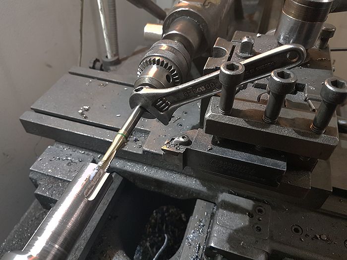 Then I turned a washer from a SS2333 bar. 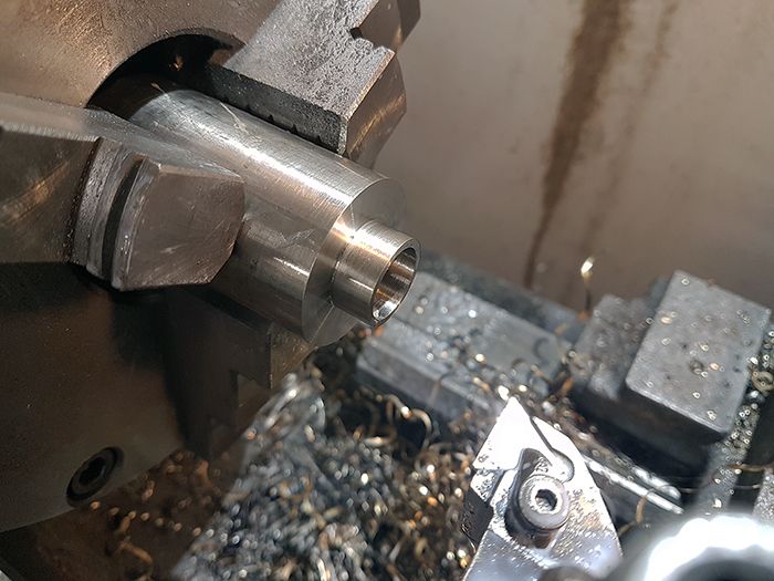 The backside of the washer got a milled slot that fits onto the end of the key. 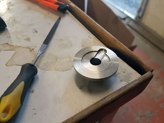 The washer was drilled through in the mill and after that I torqued the insex screw down and drilled the screw head through with the battery drill. 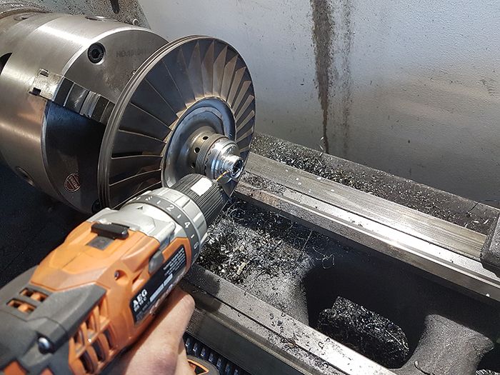 With the screw head drilled through I could remove the turbine wheel and clean everything out, now I just need to fit a 2mm stainless wire to lock the turbine wheel in place for good! 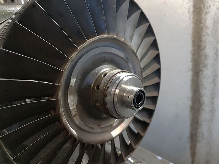 Cheers! /Anders |
|


