|
|
Post by turbochris on May 9, 2017 17:28:54 GMT -5
my old D6S turbocharger turbine had duel inlets and an NGV. The gasses in the non perforated side had to make a sharp turn. Also- guess what! the turbine wheel was stainless steel, not hastaloy or anything like that.  |
|
|
|
Post by turbochris on May 9, 2017 17:31:39 GMT -5
The newer 5HDR replacement had 2 overlapping scrolls cast into one housing and the turbine wheel was not made of stainless hahaha  |
|
|
|
Post by Johansson on May 9, 2017 22:56:16 GMT -5
Progressing steadily :-) I rather envy you guys having someone to sit and "talk crap" with about a build, my shed is rather empty of laughter . 200 kph+ should be easily achieved , Olov might need some "aero controls" for steering and stability at its full potential ;-) Cheers John Hi John, Actually meeting up was a rare occation, 99 evenings out of 100 we are working on our own with a weekly lunch time phone call if we need to discuss anything. We Swedes are a solitary breed, or at least I hope so since the alternative would be that Olov and I are social misfits.  Cheers! /Anders |
|
|
|
Post by racket on May 9, 2017 23:02:41 GMT -5
LOL ...........I'll go for the second option ;-)
|
|
|
|
Post by smithy1 on May 10, 2017 19:58:51 GMT -5
LOL ...........I'll go for the second option ;-) LOL...  Cheers, Smithy. |
|
|
|
Post by Johansson on May 12, 2017 12:38:33 GMT -5
I spent last night working on the turbofan, first up was to make a ss2333 stainless bushing to fit the turbine wheel with 30mm bore on the 25mm drive shaft. 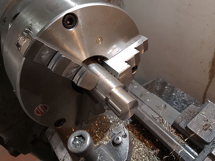 A snug push fit, perfect! 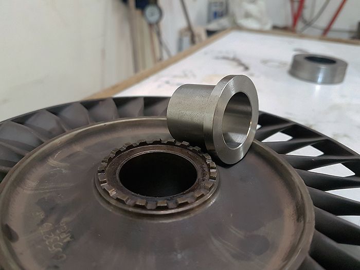 The bushing fitted to the turbine wheel, this surface will push against the rear bearing inner race. 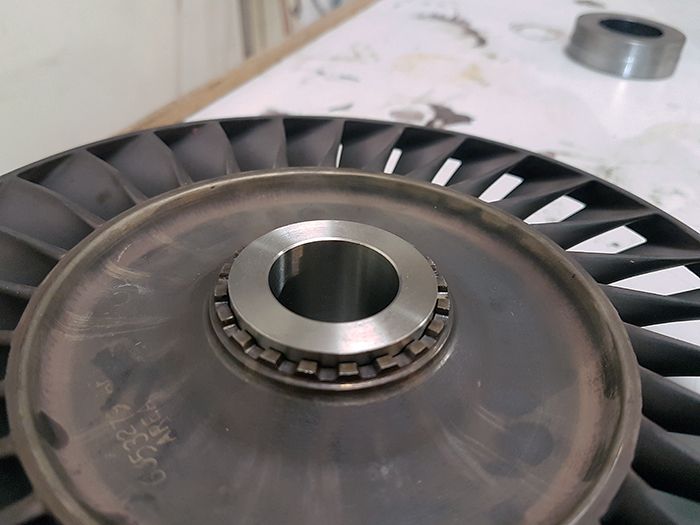 Something I have been thinking a lot about is how to couple the NGV to the shaft tunnel, my first idea was some kind of bolt circle with countersunk and wire locked screws but the lack of space made this almost impossible to machine. While standing there scratching my head I suddenly realized that I could make a threaded coupling in the lathe! 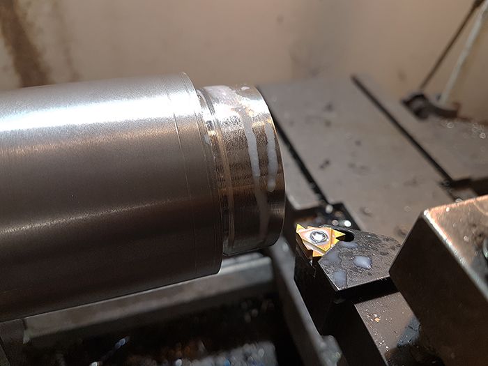 The shaft tunnel threaded. 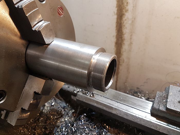 The matching nut that is going to be welded to the NGV. 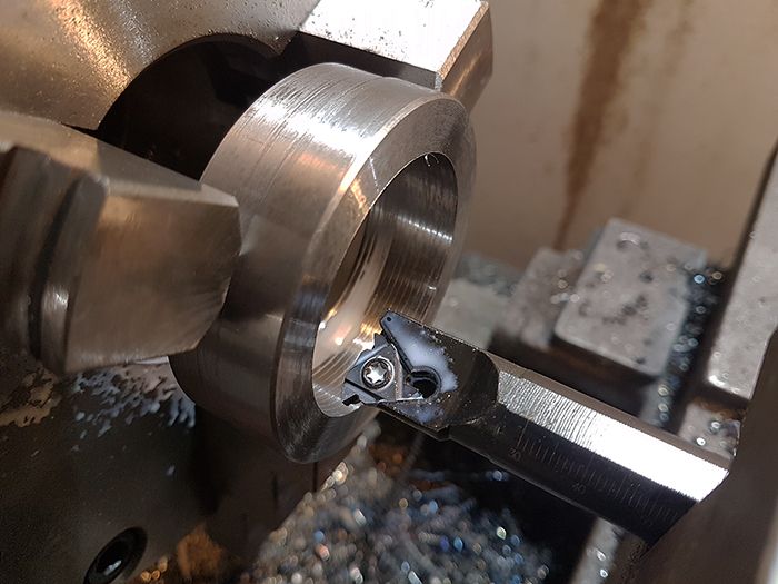 Both parts finished, but will they fit? 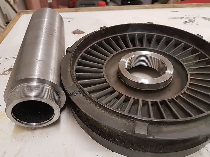 Oh yes they do. 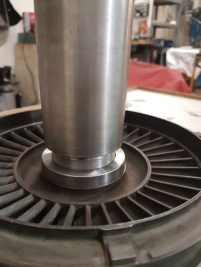 Here the exhaust manifold is placed over the NGV, next up is to turn the inside of the shaft tunnel to a snug fit for the bearings. 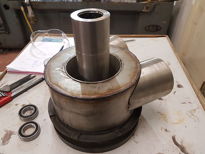 Cheers! /Anders |
|
CH3NO2
Senior Member

Joined: March 2017
Posts: 455 
|
Post by CH3NO2 on May 12, 2017 12:47:53 GMT -5
You make it look easy Anders.  |
|
|
|
Post by stoffe64 on May 12, 2017 13:07:34 GMT -5
Amazing work as always Anders!
|
|
|
|
Post by Johansson on May 12, 2017 14:31:41 GMT -5
Thanks guys! |
|
Sweetenough
Veteran Member
Joined: April 2016
Posts: 121
|
Post by Sweetenough on May 12, 2017 15:11:54 GMT -5
Still trying to figure out how it all will fit together with the fan.... Nice work Anders! I saw somewhere that the fuel flow to the EBK was calculated to 30liters/minute. Have any plan yet on what pumps to use? 10pc of biltemas finest Bosch 044 copy?
|
|
|
|
Post by Johansson on May 12, 2017 15:16:44 GMT -5
Still trying to figure out how it all will fit together with the fan.... Nice work Anders! I saw somewhere that the fuel flow to the EBK was calculated to 30liters/minute. Have any plan yet on what pumps to use? 10pc of biltemas finest Bosch 044 copy? No pumps at all will be used, we will either pressurize the fuel tank with P2 air or make a venturi injector upstream the fan so that it sucks the fuel by itself. |
|
Sweetenough
Veteran Member
Joined: April 2016
Posts: 121
|
Post by Sweetenough on May 12, 2017 15:21:22 GMT -5
Aha, interesting! Innovative as always! Keep up the good work!
|
|
|
|
Post by Johansson on May 12, 2017 15:28:24 GMT -5
Aha, interesting! Innovative as always! Keep up the good work! The venturi injection was Johns idea, clever as always. |
|
|
|
Post by racket on May 12, 2017 19:33:35 GMT -5
Yep , there'll be plenty of "suction"at the fan inlet , theoretically around 2.5 psi below ambient with our 600 ft/sec inlet air speed , enough suction to lift fuel 5 feet , so if the fuel tank is just below the fan inlet, fuel can't flow until the fan spins .
Its a bit like the old "suck through" turbo setups , where the fuel exiting the carb hit the comp wheel and was smashed into a fine atomisation , that 7.7" dia fan at >30,000 rpm will do a good job of atomising even the biggest droplet size exiting the fuel "spray bars" .
Back in 1999 I was experimenting with water injection into the comp inlet of my TV84 engine , I had a 5 litre container of water with a windscreen washer pump feeding a plastic tube ring wired to the FOD screen , the tubing had small holes melted into it for the low pressure water supply to be distributed around the comp inlet .
I found that once up to a P2 of 20 psi the inlet suction started drawing water from the container , the pump being wired to a pressure switch set for 30 psi P2 .
Coarse water injection into an alloy comp wheel does erode the inducer over time , but the Fan is high tensile steel so able to cope with the water droplets .
If flow from suction alone isn't quick enough then a few extra psi of P2 bleed will soon correct that , a bit of flow rate experimenting using water instead of fuel will soon indicate whats required.
Cheers
John
|
|
turboreno
New Member
Joined: July 2014
Posts: 5
|
Post by turboreno on May 12, 2017 20:25:17 GMT -5
My experience is that even steel airfoils can be damaged during water washing if the leading edge radius is too small. If it is a knife edge you may have some damage.
Thanks, Ron
|
|