CH3NO2
Senior Member
  
Joined: March 2017
Posts: 455 
|
Post by CH3NO2 on Nov 8, 2017 22:31:49 GMT -5
Hi Scott, That's a fantastic build!  If you redesign your flame can, try to bring the air in at the bottom of the flame tube plenum. If you can rotate your compressor outlet connection to the bottom of the flame tube, just beneath the convergent section of the flame can, the air will have more free area to spread out with less obstruction before traveling up the plenum. It may conserve a little pressure drop and balance the flow a little more. BTW, is the after burner a hollowed out exhaust resonator?  Tony |
|
donagin
Member
 
Joined: November 2017
Posts: 24 
|
Post by donagin on Nov 13, 2017 19:37:36 GMT -5
Hi Scott. Nice build. You are way ahead of me. Love those sled rails! Nice sled! One thing that concerns me is the oil ports on the turbocharger, it looks like the drain port is pointing to the side of the turbo and not straight down. If it were a ball bearing turbo you might have been ok but a journal bearing turbo needs a gravity drain for the oil so the drain port has to be pointing downwards. Cheers! /Anders Hi Anders, Is it practical to drain oil from a turbo where the shaft is pointing in the vertical direction instead of the horizontal? I know this is not what you were referring to here, but it got me wondering. Thanks, Don |
|
|
|
Post by Johansson on Nov 14, 2017 0:12:20 GMT -5
Is it practical to drain oil from a turbo where the shaft is pointing in the vertical direction instead of the horizontal? I know this is not what you were referring to here, but it got me wondering. Thanks, Don Nope, same thing there. The bearing core is built so that the shaft needs to be somewhat horizontal and the drain port at the bottom (give or take 20° or so) if the oil is to evacuate the turbo, if not it will still work but the oil will pool up inside the housing and start leaking past the shaft seals. |
|
|
|
Post by slittlewing on Nov 14, 2017 16:59:53 GMT -5
Thanks for all the input and comments chaps! John - Sounds good, I have remodelled with 4.5" FT instead of 5" and added 8x 2mm cooling holes below the "lid", I have also revised my primary holes to add some above and below the 80deg sprayline but to keep the same primary area as advised by andym. Tony - I like your suggestion and it does make sense.. I modelled putting the air inlet at the bottom near the cone (unfortunately did it on my work PC so don't have the screenshots to hand) but as the cone into the turbine would have to be "beaten"/welded to transform it into a rectangle (to mate with the turbine flange), I think there would then be very very little chance of it then placing my "rattle" joint concentrically further up the chamber! I reckon I would then run into issues trying to slide my FT into the rattle joint and have it all square with the bolted flange at the far end. I could do away with the rattle joint completely if I was to put the bolted flange at the "hot end" and make a fully capped FT inside it, but I'm not sure gasket material for the bolted joint would like it too much at that temperature! I have modelled instead with a bit of an expanding section? (P.S. the afterburner is made of cones and pipe i could get easily off ebay!) Any feedback is appreciated!   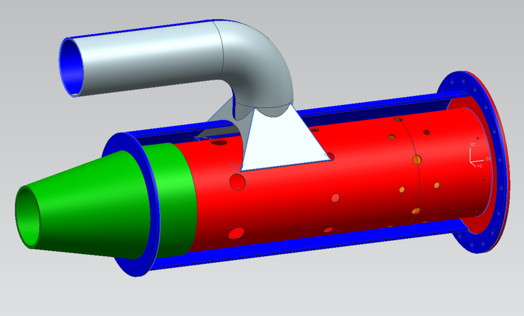 |
|
|
|
Post by racket on Nov 14, 2017 17:17:18 GMT -5
Hi Scott
Could make some of those 2mm holes at the top of the FT a bit bigger so that the air jet penetrates deeper , every second one 8mm dia , and cutback the other Primary holes to maintain the required Primary share .
Also go back to a main single row of Primary holes with your original 8 or 10 holes , you need depth of penetration
Cheers
John
|
|
Deleted
Joined: January 1970
Posts: 0
|
Post by Deleted on Nov 14, 2017 18:22:19 GMT -5
Hi Scott Could make some of those 2mm holes at the top of the FT a bit bigger so that the air jet penetrates deeper , every second one 8mm dia , and cutback the other Primary holes to maintain the required Primary share . Also go back to a main single row of Primary holes with your original 8 or 10 holes , you need depth of penetration Cheers John Hi Scott John makes a good point, but perhaps open every second 2mm hole to 8mm...... keep the 6 larger holes in the lower group for penetration, and reduce the lower of the pair holes All best Andy |
|
ausjet
Veteran Member
  
Joined: May 2013
Posts: 135 
|
Post by ausjet on Nov 14, 2017 20:25:03 GMT -5
Have a look at how I did my flame tube slip joint for some ideas. jetandturbineowners.proboards.com/thread/966/hc5a-kart-build?page=2Bought a standard turbo flange from eBay. Measured the circumference of the flange inlet and made the flame tube cone outlet slightly smaller. If you have access to an oxy/acet kit it makes it a lot easier to make the square Transition, plus your manipulating thin stainless rather than your thicker outer can |
|
|
|
Post by slittlewing on Nov 18, 2017 10:24:36 GMT -5
ausjet - I had seen your thread, I must say you have done a lovely job on your flame tube fabrication! I don't have oxy/acet unfortunately, I dont think I can get my "rattle joint" inside the turbine rectangle with your level of accuracy but I guess can have a go at grinding the base of the cone to get it square further up, to allow for cold air feed in that section. I have remodelled with your recommended holes John/andym, what do you reckon? 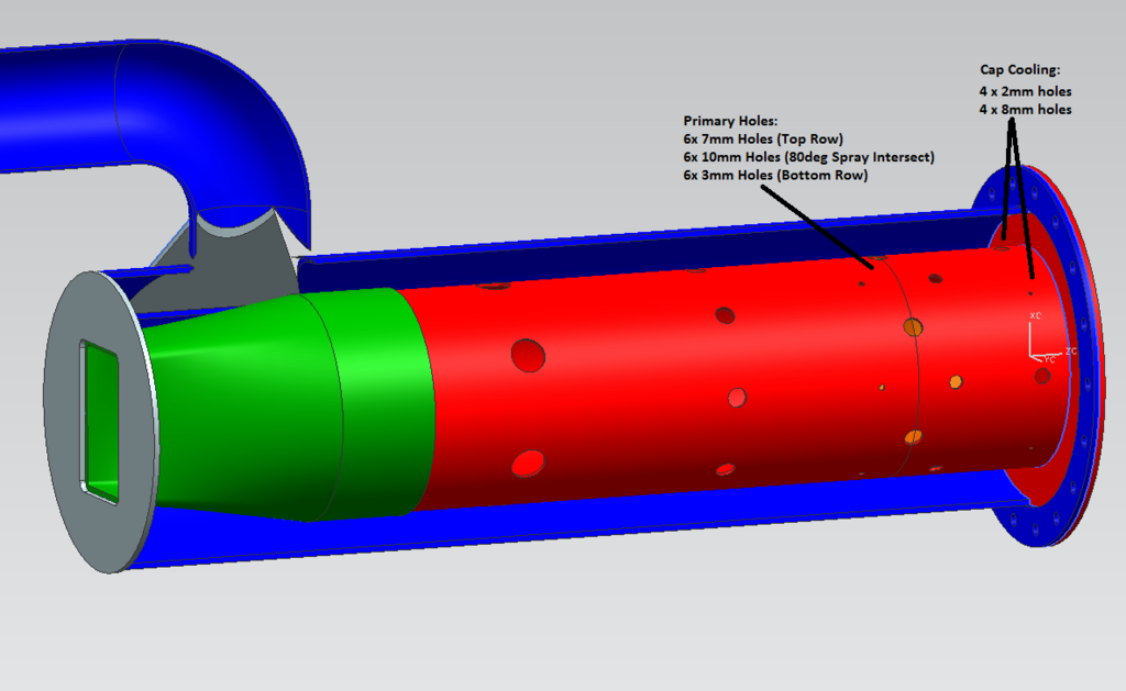 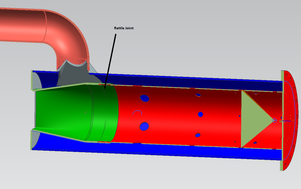 Thanks in advance, Scott |
|
|
|
Post by turboron on Nov 18, 2017 13:36:05 GMT -5
Scott, I was not having much success in dismantling turbochargers with a propane torch until I purchased a Turbo Twin Torch. It has two tubes feed from a common manifold and tank. Big improvement in capability over the single tube. About $50.00 US dollars as I recall.
Thanks, Ron
|
|
|
|
Post by racket on Nov 18, 2017 16:21:40 GMT -5
Hi Scott If your slip joint is at the rectangular inlet it doesn't have to be a perfect fit , as long as you're 95% of the area the few leaks can be added to the Tertiary hole area flow, which if you are using plain rather than bellmouthed holes mightn't be a bad thing. I use to make the snout a separate piece to the funnel and weld it on jetandturbineowners.proboards.com/attachment/download/68 much easier job Cheers John |
|
Deleted
Joined: January 1970
Posts: 0
|
Post by Deleted on Nov 19, 2017 4:19:12 GMT -5
Hi Scott
I think the flame tube and C/C are looking good.... Looking forward to seeing it come together
All Best
Andy
|
|
|
|
Post by slittlewing on May 31, 2018 6:47:18 GMT -5
Hi chaps, Long time no update... I was going to abandon the project and even tried to sell it but have now re commited and got another/more suitable vehicle to put the engine on!! Details to follow! I will be making the combustor soon as per the previous screenshots! So onto the afterburner/tailpipe design, what do you think of the one below? It’s a 3.5” exducer, twice area = 5” diameter expansion zone, exit cone is 2.5” to match the inducer. Or should I go smaller on the exit cone? I have modelled it with a bolted flange, support ring and circular copper pipe with 10* 2mm holes for injection: 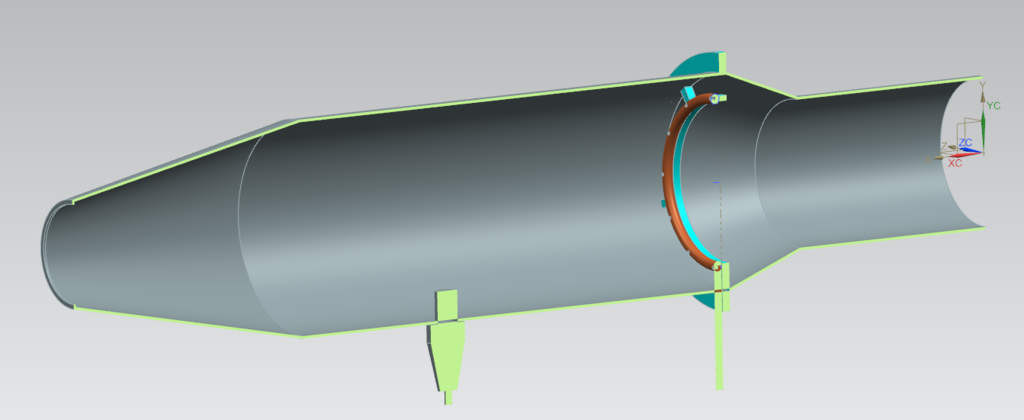 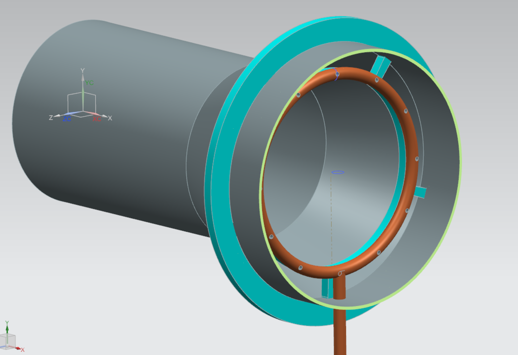 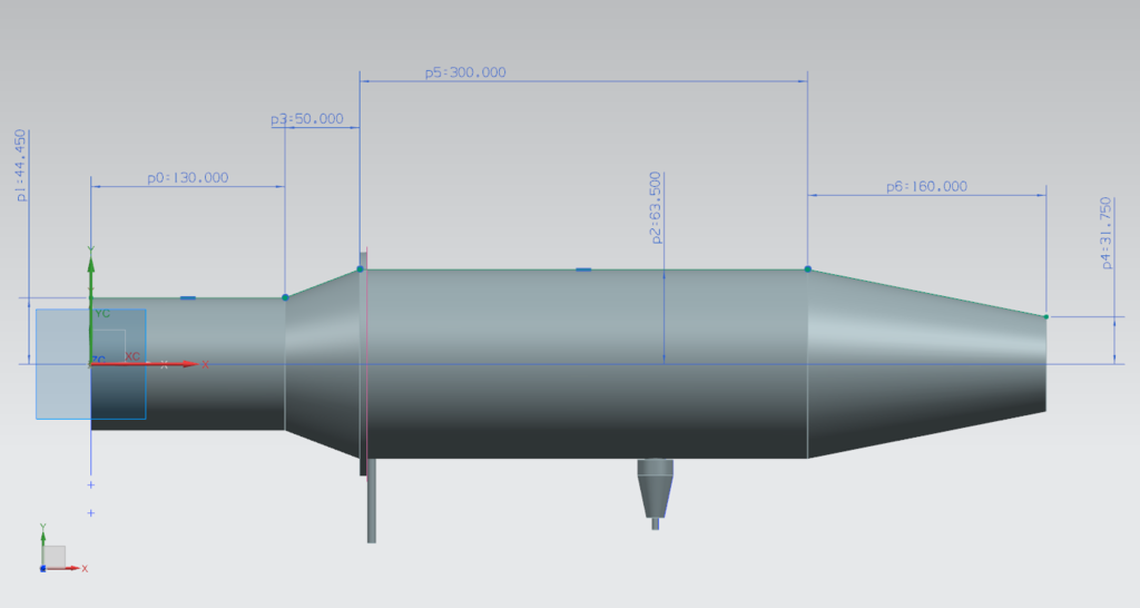 Any advice would be much appreciated, Cheers Scott |
|
Deleted
Joined: January 1970
Posts: 0
|
Post by Deleted on May 31, 2018 7:35:25 GMT -5
|
|
|
|
Post by slittlewing on Jun 4, 2018 5:56:22 GMT -5
Thanks Andy, I’ll scale that down slightly for my 2.5” inlet size!
|
|
|
|
Post by slittlewing on Jun 5, 2018 10:24:34 GMT -5
How’s this for a mk2 Andy? It scales to a 74mm exit hole (71 after wall thicknesses) for my 63.5mm inducer dia? 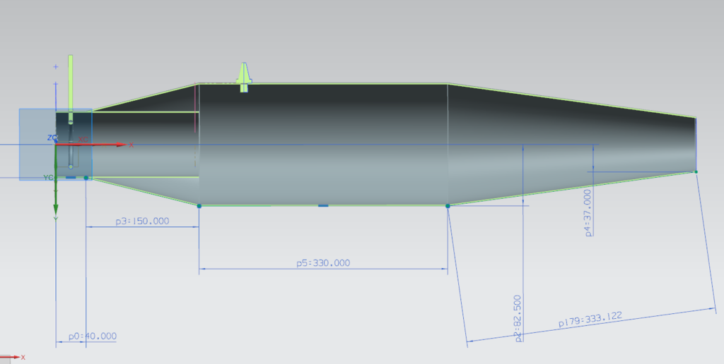 Many thanks! Scott |
|