Deleted
Joined: January 1970
Posts: 0
|
Post by Deleted on Jun 5, 2018 13:13:45 GMT -5
looks good to me :-)
|
|
|
|
Post by slittlewing on Jun 13, 2018 6:47:34 GMT -5
So here is the new vehicle I am going to attempt to squeeze the engine into: 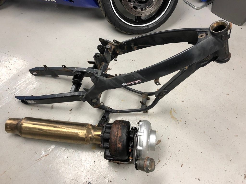 It’s an xt125 motorbike chassis and there isn’t much room!! I may need to widen the frame rails a little. I want to try and mock up the positioning before I send the files for laser cutting, which leads me to another question.. Is it possible to “cheat” a little on the idealised combustor size and use the reducing cone as part of the 15” length? This could shorten my combustion chamber from 450 to 380mm which would help quite a lot! Example picture below (simplified flame tube hole design not actual) 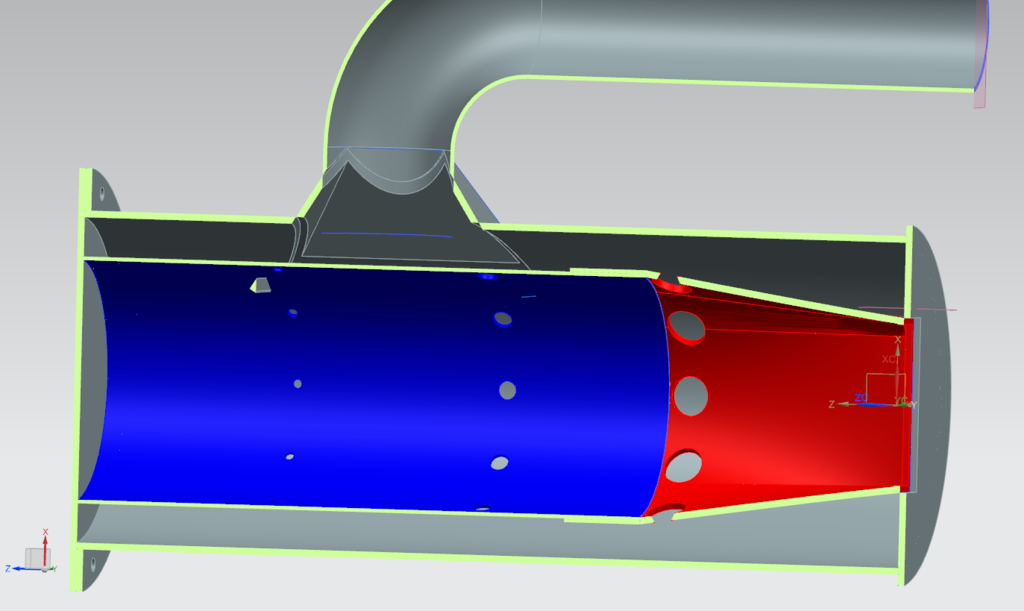 Your assistance is much appreciated, Cheers Scott |
|
|
|
Post by racket on Jun 13, 2018 17:04:37 GMT -5
Hi Scott
Yep , the length can be shortened as in your pic , it can be shortened a tad further if you're not too concerned about fuel efficiency by reducing the distance between Primary and Secondary holes, just don't skimp on diameters though .
Your distance from the "lid" to Primary holes is pretty long , I gather its because of the fuel spray angle , ideally the holes need to be positioned at half the flametube diameter from the lid , assuming the outlet of the spray nozzle is at the lid , so maybe reduce some distance there if you want.
Cheers
John
|
|
|
|
Post by slittlewing on Jun 14, 2018 16:05:14 GMT -5
Thanks alot John! I will take your advise and hopefully settle on the 350mm length below:  |
|
|
|
Post by racket on Jun 14, 2018 16:18:13 GMT -5
Yep
|
|
|
|
Post by slittlewing on Jun 15, 2018 15:26:40 GMT -5
Small update.. Started to hack away at the frame after building a jig to hold it. I will have to make new shock absorber supports to move it out of the way from the tailpipe route. I think my main issue is going to be heat management, with the plastic fuel tank sitting an inch away from the turbine! This is my very rough mock up so far... 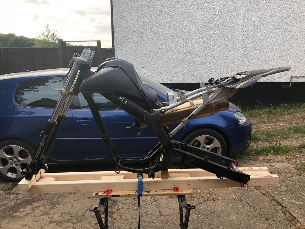 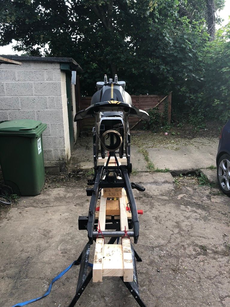 And first usable part of the new engine, kerosene injector boss with 13.5 danfoss injector. 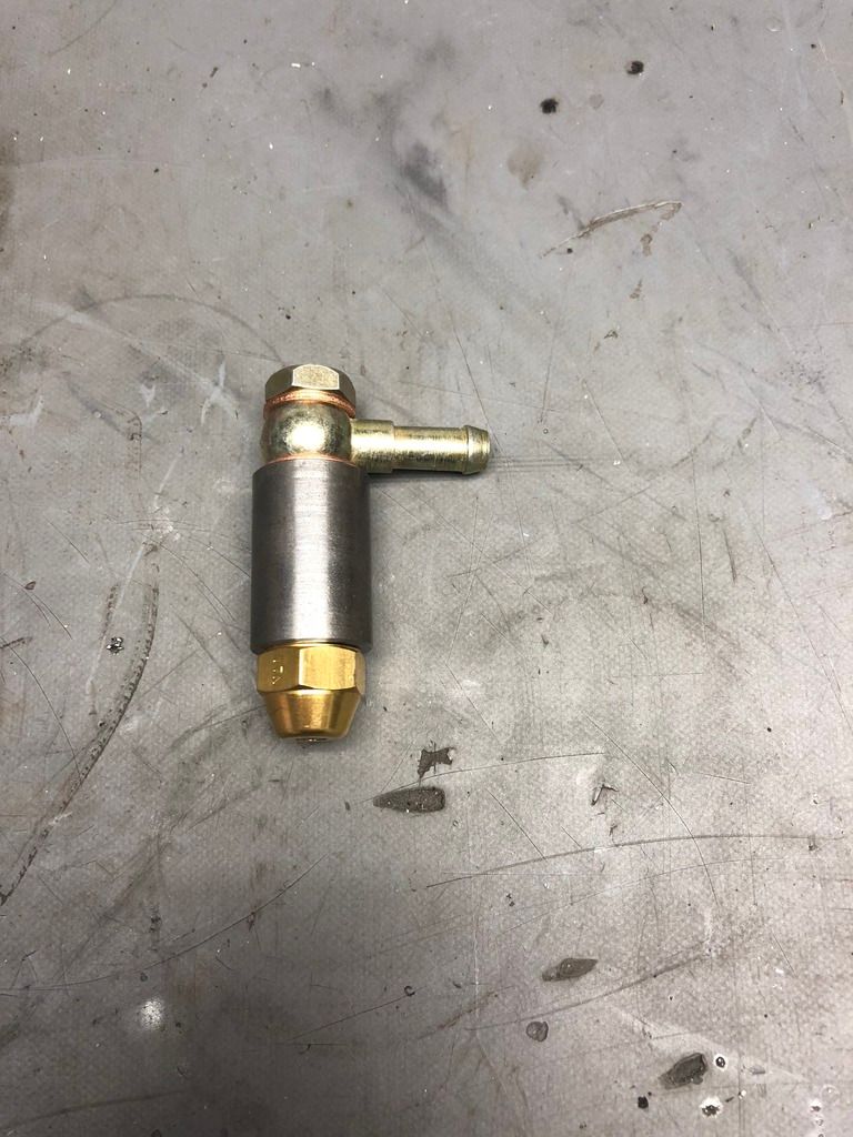 |
|
|
|
Post by slittlewing on Jun 20, 2018 15:01:01 GMT -5
Another minor update.. I have cut the combustion chamber tube to length, it’s 3mm wall mild steel. I have also made the nozzle that goes to the turbo (not quite finished welding). I used a section of the old tailpipe and did a template on cad, cut it out and taped it to the tube, sprayed white paint over it and then accurately angle ground the sprayed on pattern. A bit of hammering later and it’s a close fit to the OEM Holset gasket: 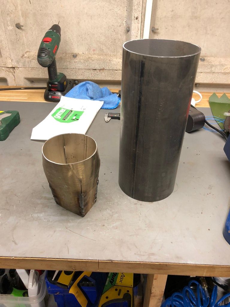 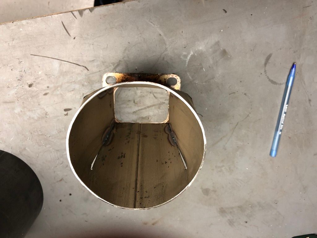 All the laser cut metalwork for the combustion and afterburner sections is on order so hopefully a considerable update soon.... |
|
|
|
Post by slittlewing on Jun 23, 2018 5:23:31 GMT -5
Today I would like to say a big thankyou to turboron for your “frozen turbine” method. I have known for a while that I need to turn the oil ports vertically but it was even More obvious after stripping the old engine down, there was oil all over the turbine blades etc. I hope the oil seals are not fubared after running it briefly horizontally! So I followed the instructions to the letter, borrowed a sievert propane torch from work and also added Kroil penetrating oil into the mix along with freezer spray onto the inner section to try and maximise the temperature differential. Jacking off the oil ports using the bolts with the heating cycles and punch hammering released the housing  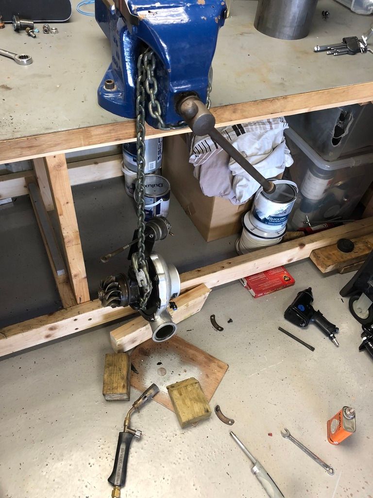 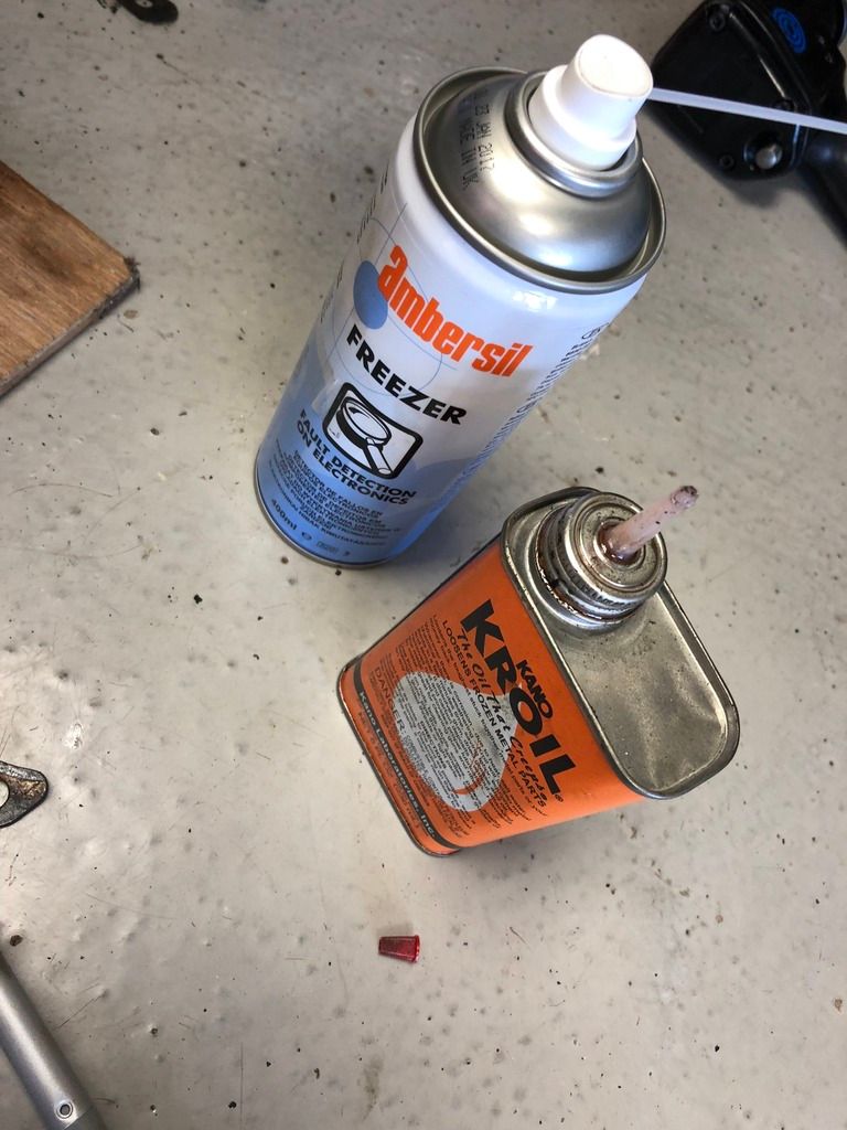 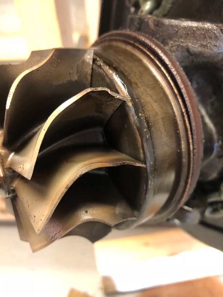 Only issue is that it has exposed some old tip damage to a few of the blades, I guess it’s ok to continue using? I don’t want to try bending them back in case I snap the tips off! Cheers Scott |
|
|
|
Post by turboron on Jun 23, 2018 9:26:13 GMT -5
Scott, balance may be an issue. You can remove metal from the convex side of the blades on the opposite side to get a static balance. A static balance is probably okay for initial testing.
Thanks, Ron
|
|
|
|
Post by Johansson on Jun 23, 2018 14:25:34 GMT -5
As long as no material has been removed (burned off etc) from the turbine blade tips I don´t think that some backyard static balancing will do any good, you´d probably make things worse.
My 5 cents is that you use this turbine shaft for the initial runs at low rpm´s and meanwhile try to source a new unit for the later high power runs.
Cheers!
/Anders
|
|
|
|
Post by slittlewing on Jun 25, 2018 2:31:06 GMT -5
Cheers for the feedback, I think I’m going to just run it as-is for now on the basis that it probably happened a long time ago in the turbos life and it has survived this far. I will look to fix it once the engine is running etc and hope that I don’t get turbine failure/explosion into my man region whilst on the bike. There are replacement wheels and rebuild kits on eBay for £200 but I’m not sure if they are as strong as the OEM wheels or if they are “cheap Chinese” stuff!? rover.ebay.com/rover/0/0/0?mpre=https%3A%2F%2Fwww.ebay.co.uk%2Fulk%2Fitm%2F262249420981 |
|
|
|
Post by racket on Jun 25, 2018 4:08:15 GMT -5
LOL..........a lot of OEM wheels are "Made in China" , checkout E and E World Turbo www.worldturbocharger.com/ , all of the turbo manufacturers have had chinese plants for many years |
|
|
|
Post by slittlewing on Jun 25, 2018 15:07:48 GMT -5
Fair play, maybe I’ll go down the Chinese shaft route then!! Finally an update of real “substance” after the CADathon, my laser cut steel arrived at 5pm and it’s mostly already rolled and welded. I hope to get the main combustor done this week and the welding is better than my last attempt now I have an auto darken mask and can see!! Here’s how it’s shaping up... 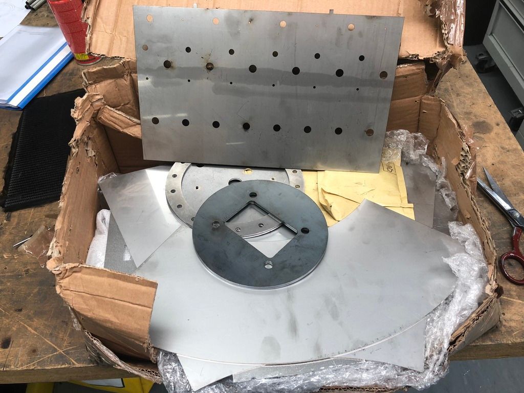 Gasket cutting (1mm 200deg rated) 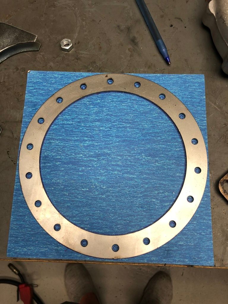 Locating tabs to centralise the flame tube: 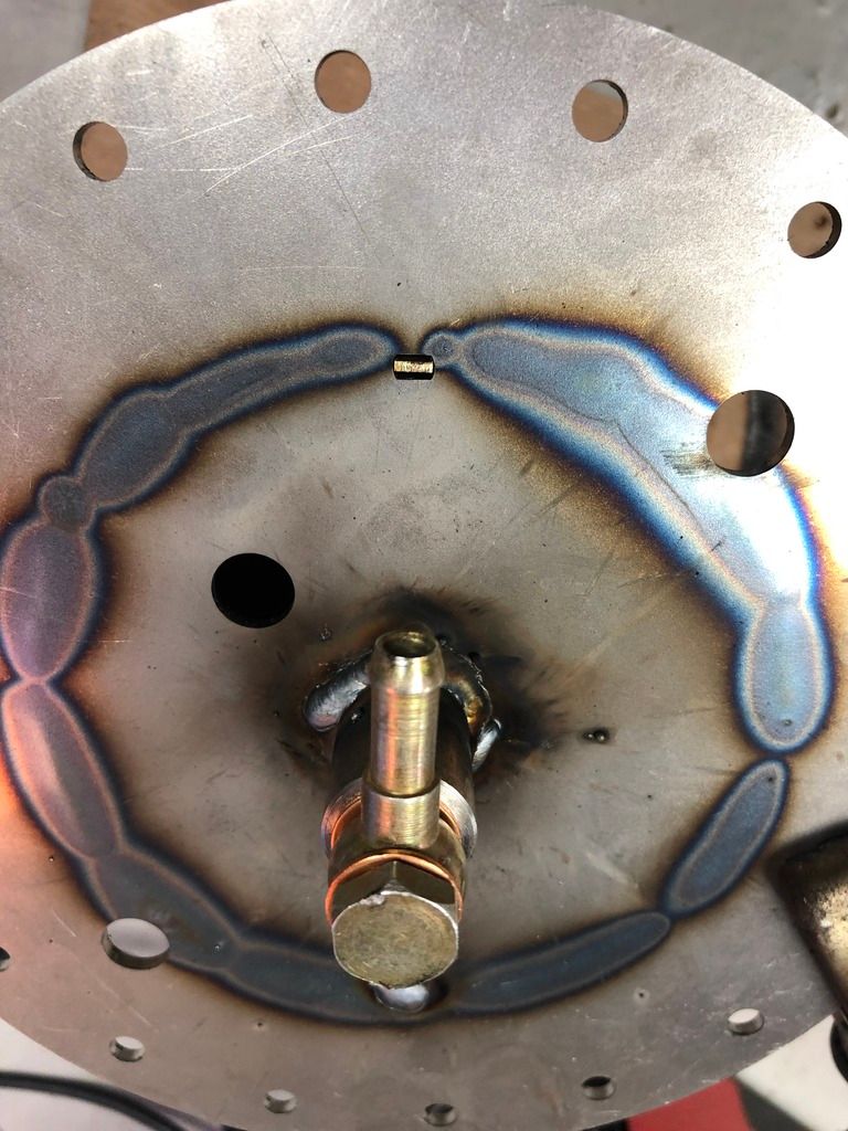 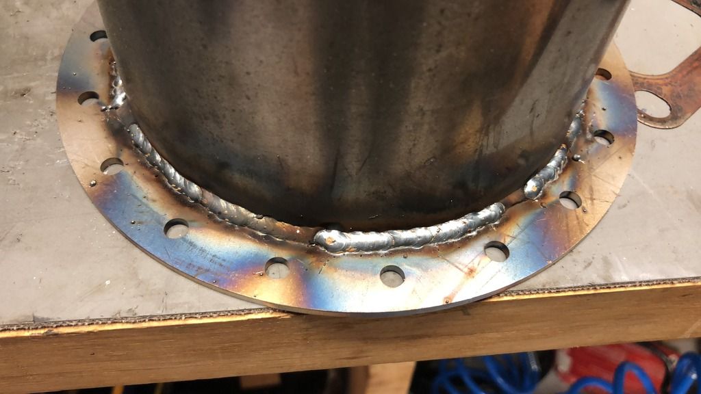 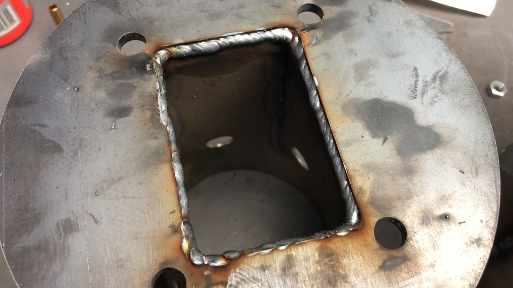 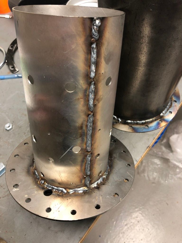 |
|
|
|
Post by slittlewing on Jun 27, 2018 15:35:13 GMT -5
|
|
|
|
Post by slittlewing on Jul 1, 2018 15:39:59 GMT -5
As planned, today I managed to get the engine mounted in the frame. A few other things - spark plug is mounted (I use m18 to m14 steel plug adapters off eBay for about £3 and weld them in as a boss) Radial Propane injector made using stainless “thread extension” from ebay, modified and inserted into a standard 1/4 bsp hose barb (tapped internally to m10 1.25) 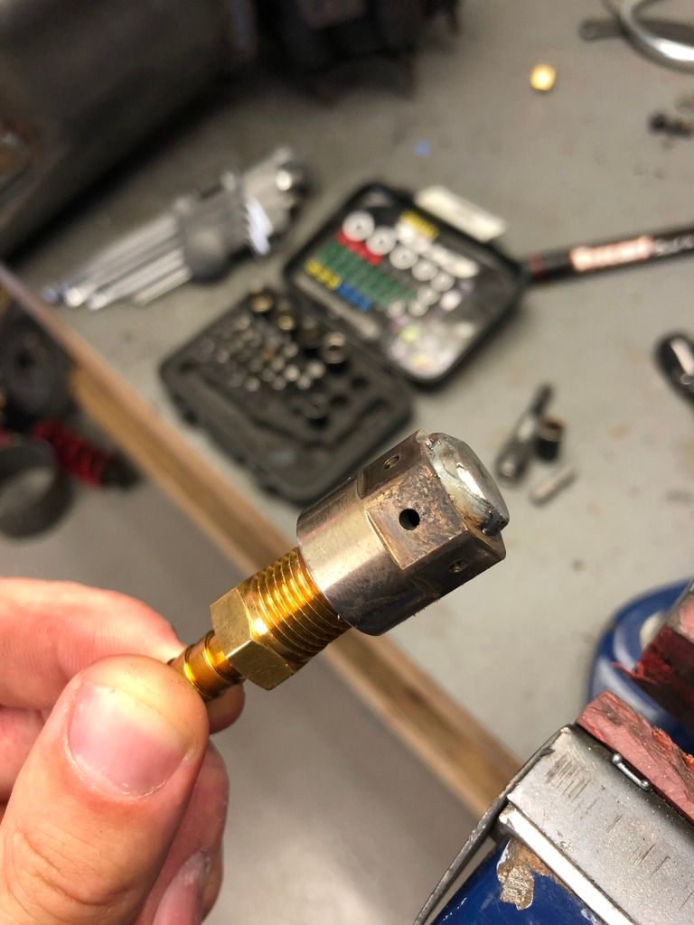 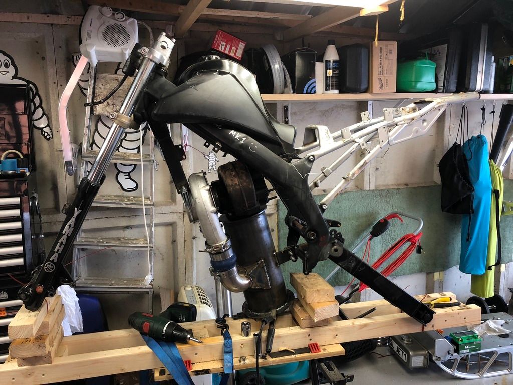 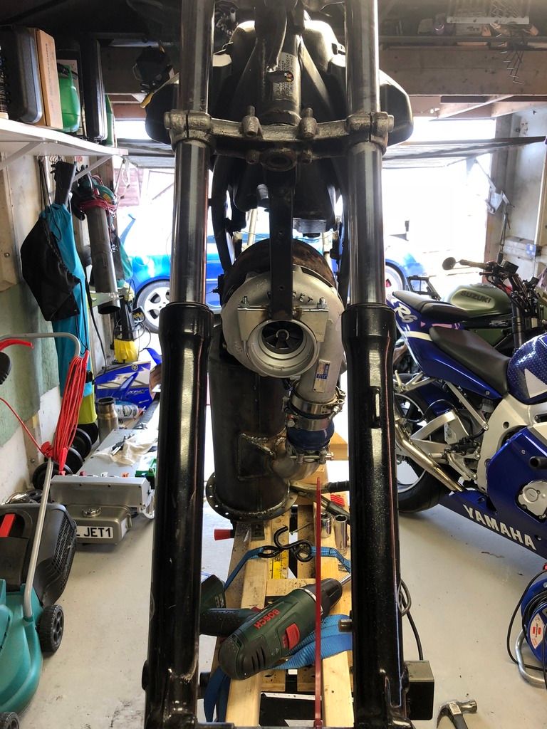 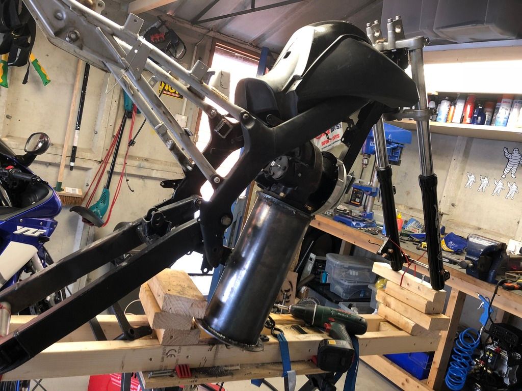 Next is the afterburner/tailpipe fab (awaiting material), shock repositioning (awaiting short shock) and need it on its wheels (wheel refurb to be done and slick tyres fitted purely because they look nice!) |
|