Post by slittlewing on Nov 4, 2017 13:46:02 GMT -5
Hi there!
I'm Scott, and have been pointed to this site by Andy after he saw the video of my DIY Gas Turbine Engine on Youtube. He has pointed me towards this forum so I thought I would do a "build thread" although the jet is already built (better late than never).
I haven't had any help thus far since building the engine so any advice or comments on things that could be improved would be most useful! I have not done any calculations in building it, just sized things on what "looks right".
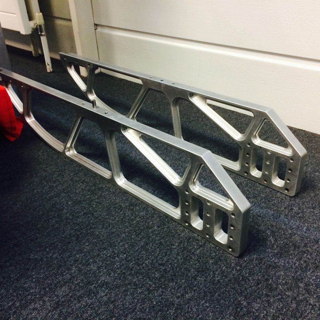
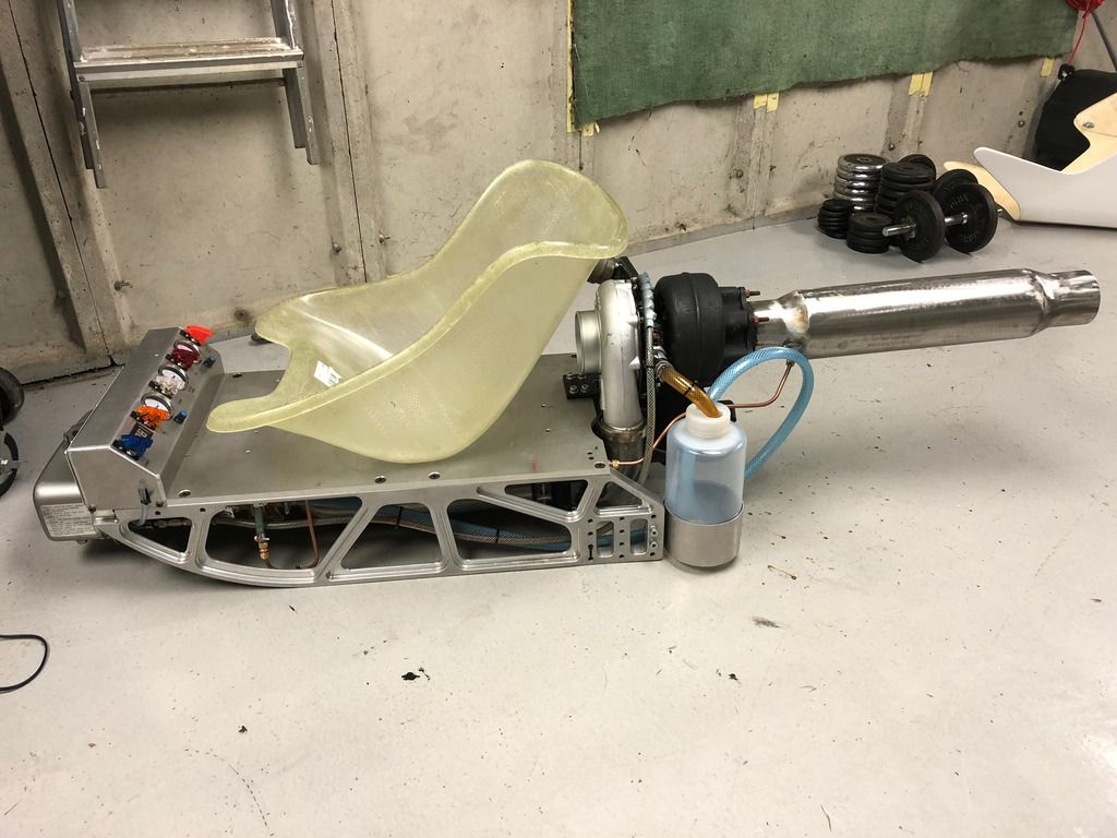
The build started when I obtained the "sledge" rails from work after they were being chucked out. I thought I could make a rather attractive sledge and then thought.. why not build a jet engine for it! Always fancied making/owning one as they are quite a spectacle.
Heres the details:
TURBO
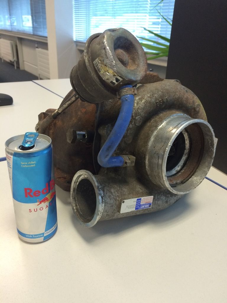
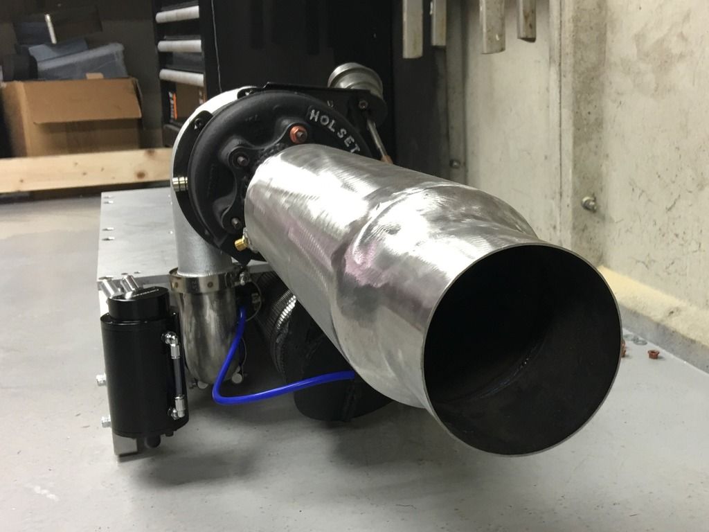
The turbo is a Holset WH2D model, I think its the largest they make and originally from a 10L Cummins Diesel. I don't know much about its history but it had a rebuild tag on it when purchased and there is a normal amount of bearing play.
The compressor inlet is 4" and it weighs 25kg, I think it can deliver 3 bar boost in "normal" use but I cant find a compressor map for it.
COMBUSTION CHAMBER
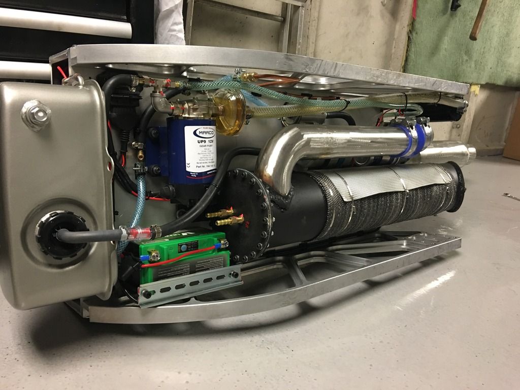
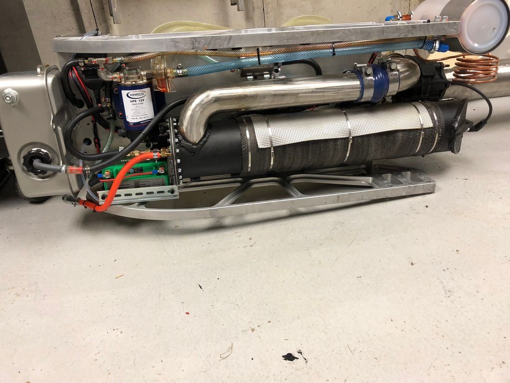
Whilst everyone seems to build their combustion chambers in direct line to the turbine flange (which I realise is most efficient to not lose energy from the expanded/hot gas), I wanted the combustion chamber to be invisible to the eye on the sledge for aesthetics, not poking up vertically. I therefore "underslung" it, forward of the turbo. The the hot gas has to make a 90 degree turn to enter the turbine flange in this case.
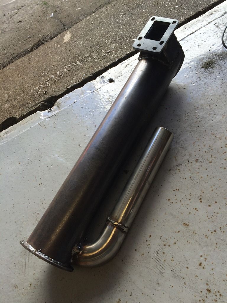
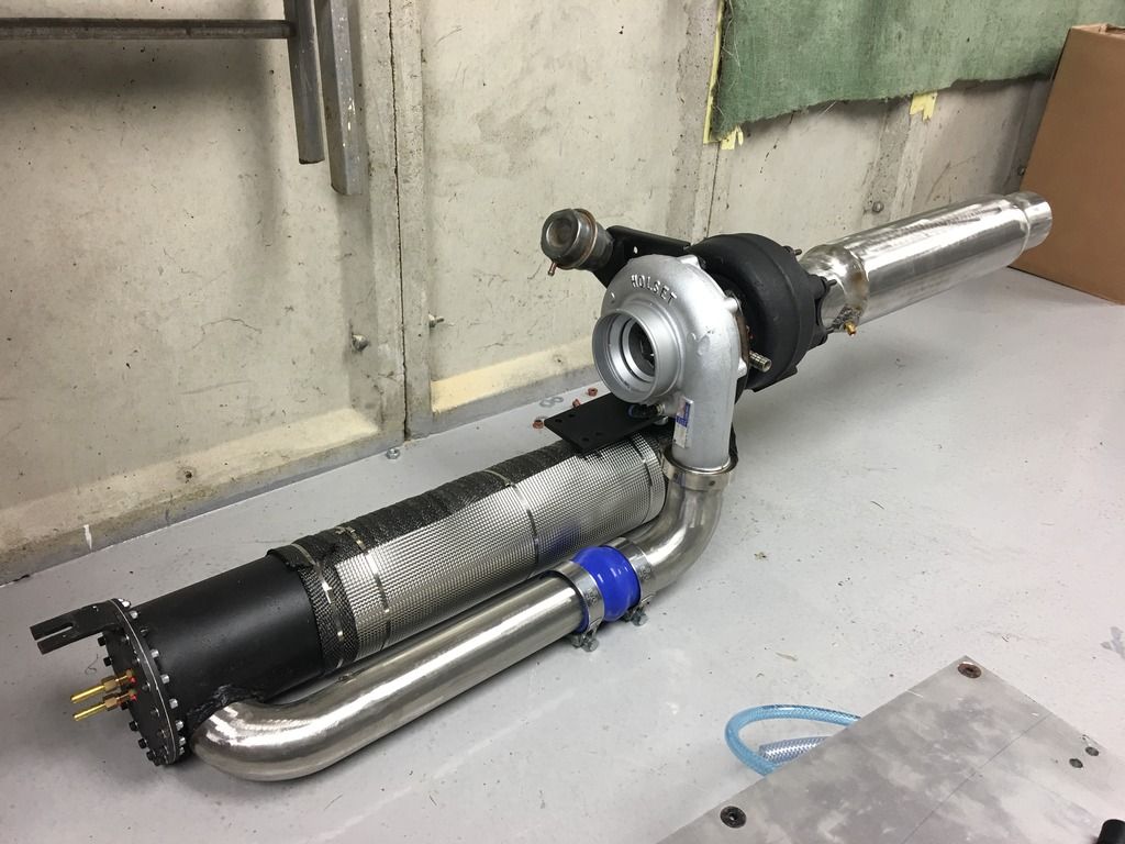
The combustion chamber is made from 5.5" steel pipe, I went for a 5mm wall thickness. I know this is massive overkill, but I wanted complete confidence it wouldn't blow up when weakened/heated! I had the turbo flange and end flanges laser cut from CAD which I did.
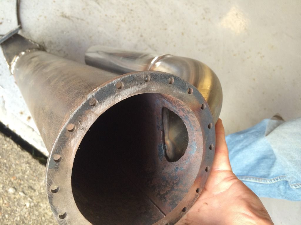
The inlet to the combustion chamber is 2.5" steel pipe and connects to the turbo via a "V band" clamp. I angled the air inlet to the combustion chamber to enter at a tangent and create "spin" of the air around the flame tube.
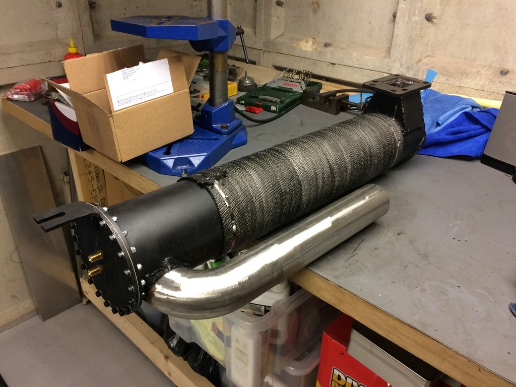
Being quite narrow at 5.5" (to fit under the sledge with some ground clearance), I made it quite long at around 800mm. I'm sure it could be half the length but I thought there wasnt much disadvantage other than weight, it just allows for more time for the flame to burn.
FLAME TUBE
Probably one of the biggest unknowns was the flame tube. I know that there is some science if you do it properly, using a tube with certain amounts of holes and spacing. I decided to take the easy option and use perforated sheet rolled into a tube, purely because I had seen a website where it had worked for someone else. My thought was that whilst there is a much greater "hole" area than required, the flame can draw in as much air as it wants to.
I also added some "swirl vanes" to the outside of the flame tube (laser cut). This was firstly to try and keep the air spinning around the flame tube (in my head, pinning it to the outside via centrifugal force unless drawn by the flame), and secondly it provides some blockage to the airflow. I thought this was beneficial to create something for the turbo to push against (as in a vehicle engine) and not create something too "free flowing" which would mean the turbo would end up overspeeding to actually push enough airflow to make boost.
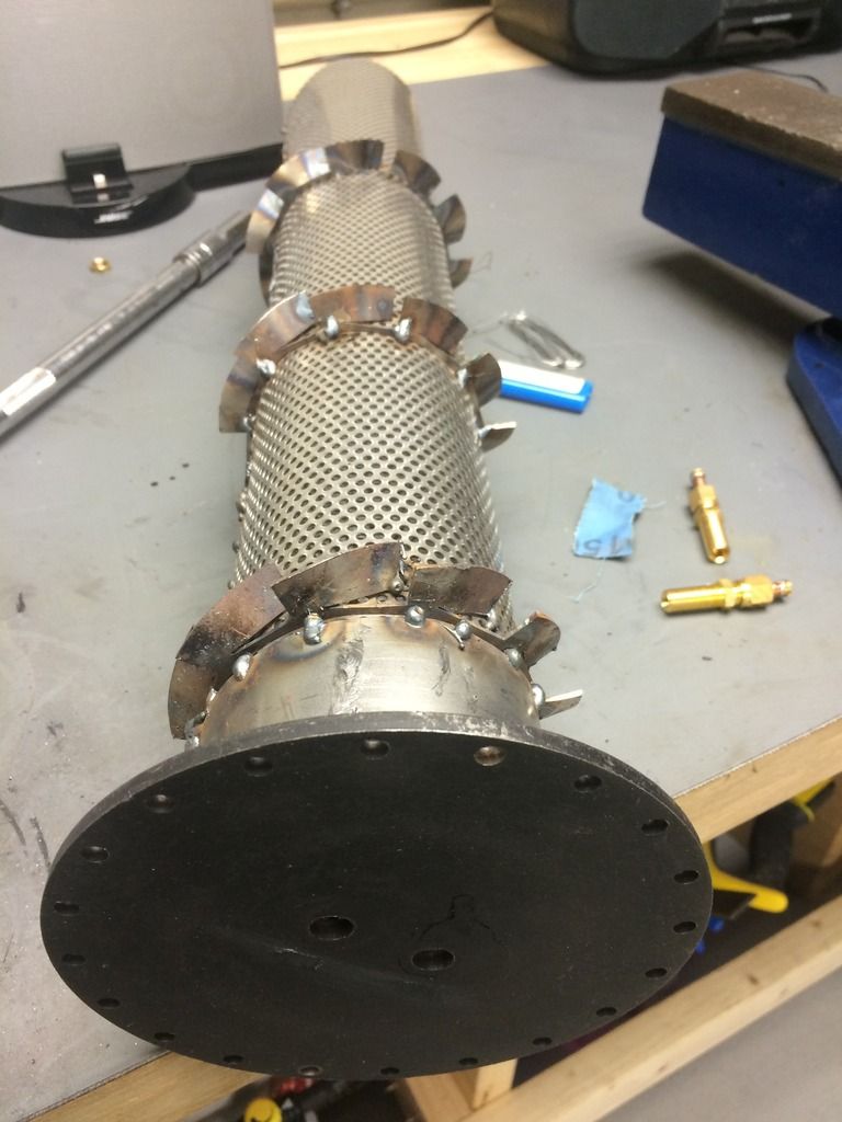
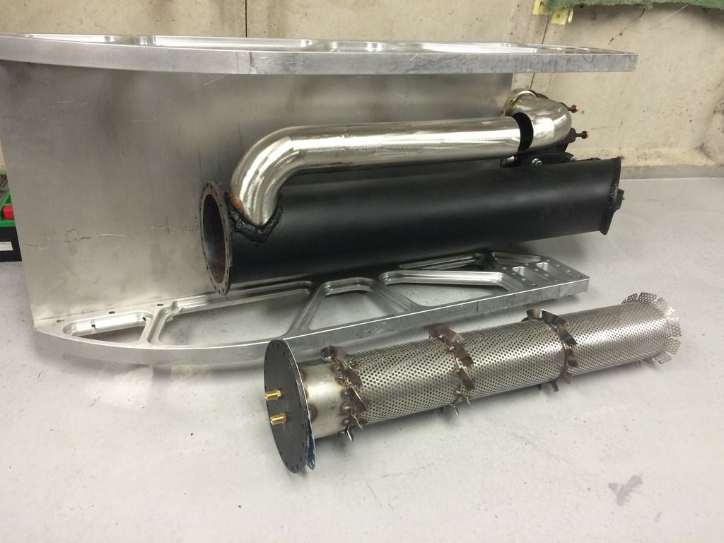
I also blocked the first few inches of the flame tube (where the compressed air enters) to avoid the fresh air blowing across the fuel injectors.
SPARK PLUG/IGNITION
I positioned the spark plug at the very back of the combustion chamber, before the turbo. I wasn't sure if it was too far back (and the flame might just blow out of the turbine) but it does work and allow the flame to propagate back into the flame tube.
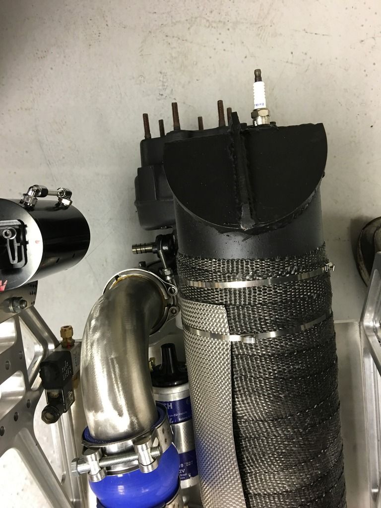
I use a relay with a capacitor to generate a pulsed voltage, which goes to a Bosch Ignition coil driver (from a Mk2/Mk3 Golf etc), which goes to a Bosch coil.
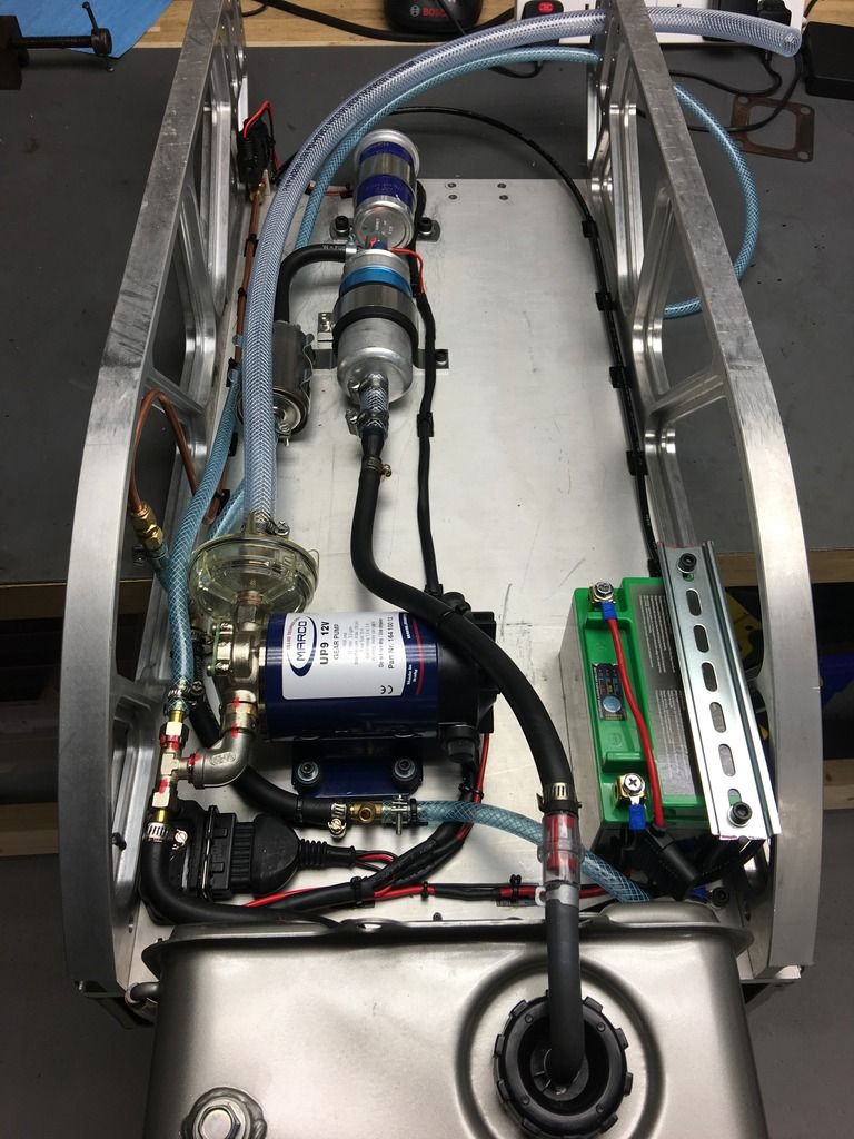
FUEL SYSTEM
There is a propane injector, with a quick disconnect pipe at the front of the sledge. I have a propane bottle with an adjustable 0-4bar regulator for starting the engine along with a leafblower.
There is also a wet fuel system (petrol). I use a Marelli car injection pump (3-5bar) with PWM control to alter pump speed and therefore fuel flow. There is no pressure regulator in the system. For the injector, i first tried using a 0.8mm carb jet. When i tested it into a bucket, it created a single "jet" of fuel like a super soaker, not a spray. I therefore adapted a car mechanical fuel injector (from a Bosch CIS/K-jet system) instead. The bad thing is that it doesnt open until about 4bar pressure, at which point the pump is driving quite hard against zero flow.
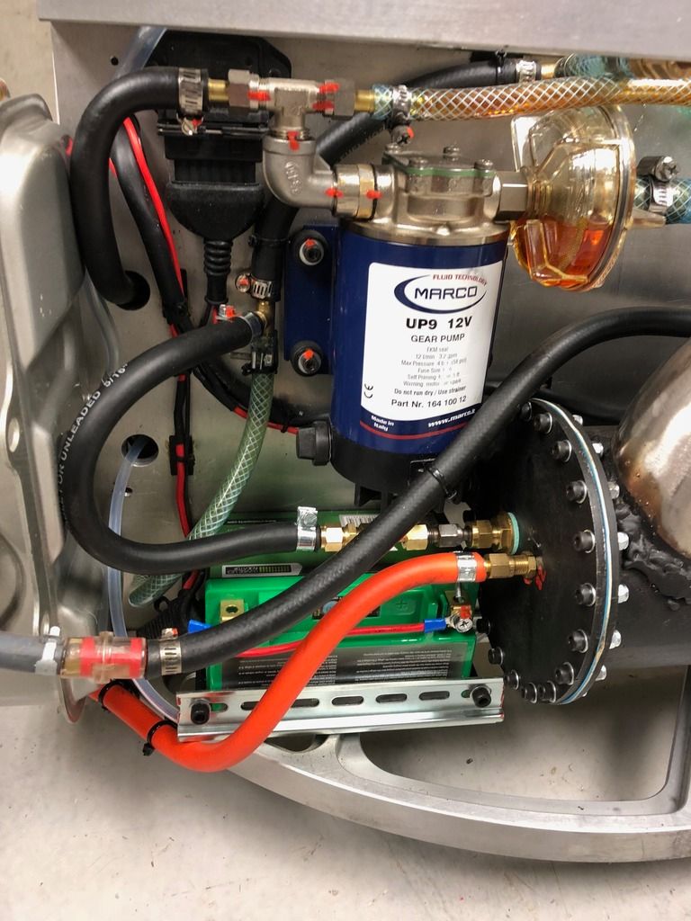
There is a high pressure fuel filter after the pump, and a gauze filter before it.
For the afterburner, at the moment there is a 12v solenoid which allows fuel flow direct to the tailpipe again through a carb jet. I will be changing this.. see below. There is a cooling loop on the copper pipe between the solenoid and tailpipe, to avoid heating the solenoid.
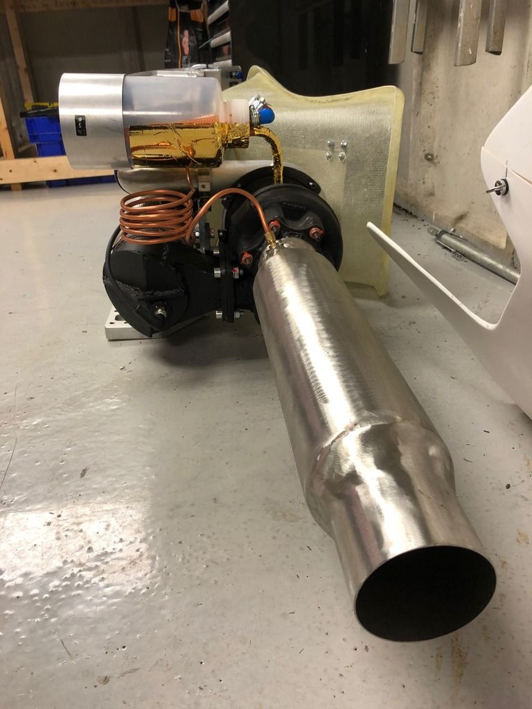
OIL SYSTEM
The oil system is a Marco 4bar bronze gear oil pump, controlled via PWM to give me pressure control. There is no oil cooler yet, I thought I would do without for short running. I am using Shell "Aeroshell" Turbine oil (for an aircraft jet engine).
The turbo oil outlet is horizontal, which I know should be vertical. I tried to remove the turbine and clock it round, but it was seized to the bearing housing so I kept it as-is. My thinking is that as long as there is positive oil pressure, oil will flow through the bearings.
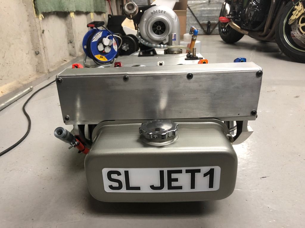
The oil tank is about 2 litres and is plastic (could do with an upgrade to an aluminium one).
OTHER
The tailpipe geometry is guessed/based on what cones I could get on ebay. I think it needs a smaller outlet cone.
The battery is a 7AH Lithium Motorcycle one, just big enough for about 20 mins running.
One of the greatest challenges was packaging everything under the sledge... its tight!
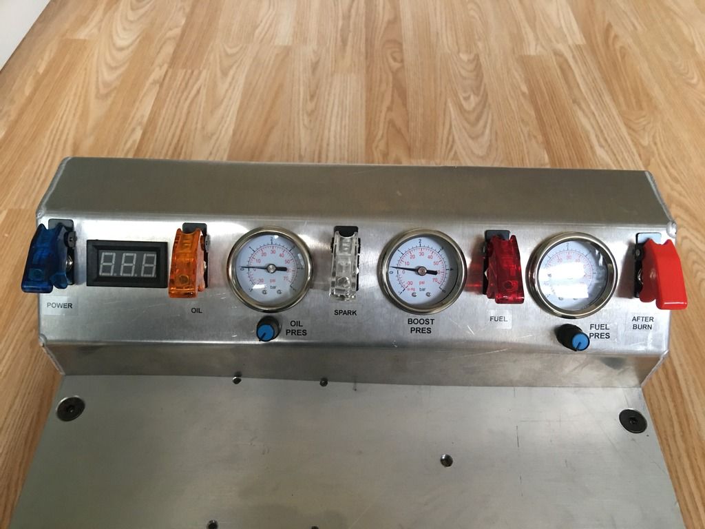
I have gauges for boost pressure, fuel pressure and oil pressure, Battery voltage readout and on off switches for the pumps, afterburner and whole
system. The pod is laser cut and bent/welded.
I'm Scott, and have been pointed to this site by Andy after he saw the video of my DIY Gas Turbine Engine on Youtube. He has pointed me towards this forum so I thought I would do a "build thread" although the jet is already built (better late than never).
I haven't had any help thus far since building the engine so any advice or comments on things that could be improved would be most useful! I have not done any calculations in building it, just sized things on what "looks right".
The build started when I obtained the "sledge" rails from work after they were being chucked out. I thought I could make a rather attractive sledge and then thought.. why not build a jet engine for it! Always fancied making/owning one as they are quite a spectacle.

Heres the details:
TURBO
The turbo is a Holset WH2D model, I think its the largest they make and originally from a 10L Cummins Diesel. I don't know much about its history but it had a rebuild tag on it when purchased and there is a normal amount of bearing play.
The compressor inlet is 4" and it weighs 25kg, I think it can deliver 3 bar boost in "normal" use but I cant find a compressor map for it.

COMBUSTION CHAMBER
Whilst everyone seems to build their combustion chambers in direct line to the turbine flange (which I realise is most efficient to not lose energy from the expanded/hot gas), I wanted the combustion chamber to be invisible to the eye on the sledge for aesthetics, not poking up vertically. I therefore "underslung" it, forward of the turbo. The the hot gas has to make a 90 degree turn to enter the turbine flange in this case.


The combustion chamber is made from 5.5" steel pipe, I went for a 5mm wall thickness. I know this is massive overkill, but I wanted complete confidence it wouldn't blow up when weakened/heated! I had the turbo flange and end flanges laser cut from CAD which I did.

The inlet to the combustion chamber is 2.5" steel pipe and connects to the turbo via a "V band" clamp. I angled the air inlet to the combustion chamber to enter at a tangent and create "spin" of the air around the flame tube.

Being quite narrow at 5.5" (to fit under the sledge with some ground clearance), I made it quite long at around 800mm. I'm sure it could be half the length but I thought there wasnt much disadvantage other than weight, it just allows for more time for the flame to burn.
FLAME TUBE
Probably one of the biggest unknowns was the flame tube. I know that there is some science if you do it properly, using a tube with certain amounts of holes and spacing. I decided to take the easy option and use perforated sheet rolled into a tube, purely because I had seen a website where it had worked for someone else. My thought was that whilst there is a much greater "hole" area than required, the flame can draw in as much air as it wants to.
I also added some "swirl vanes" to the outside of the flame tube (laser cut). This was firstly to try and keep the air spinning around the flame tube (in my head, pinning it to the outside via centrifugal force unless drawn by the flame), and secondly it provides some blockage to the airflow. I thought this was beneficial to create something for the turbo to push against (as in a vehicle engine) and not create something too "free flowing" which would mean the turbo would end up overspeeding to actually push enough airflow to make boost.


I also blocked the first few inches of the flame tube (where the compressed air enters) to avoid the fresh air blowing across the fuel injectors.
SPARK PLUG/IGNITION
I positioned the spark plug at the very back of the combustion chamber, before the turbo. I wasn't sure if it was too far back (and the flame might just blow out of the turbine) but it does work and allow the flame to propagate back into the flame tube.

I use a relay with a capacitor to generate a pulsed voltage, which goes to a Bosch Ignition coil driver (from a Mk2/Mk3 Golf etc), which goes to a Bosch coil.

FUEL SYSTEM
There is a propane injector, with a quick disconnect pipe at the front of the sledge. I have a propane bottle with an adjustable 0-4bar regulator for starting the engine along with a leafblower.
There is also a wet fuel system (petrol). I use a Marelli car injection pump (3-5bar) with PWM control to alter pump speed and therefore fuel flow. There is no pressure regulator in the system. For the injector, i first tried using a 0.8mm carb jet. When i tested it into a bucket, it created a single "jet" of fuel like a super soaker, not a spray. I therefore adapted a car mechanical fuel injector (from a Bosch CIS/K-jet system) instead. The bad thing is that it doesnt open until about 4bar pressure, at which point the pump is driving quite hard against zero flow.

There is a high pressure fuel filter after the pump, and a gauze filter before it.
For the afterburner, at the moment there is a 12v solenoid which allows fuel flow direct to the tailpipe again through a carb jet. I will be changing this.. see below. There is a cooling loop on the copper pipe between the solenoid and tailpipe, to avoid heating the solenoid.

OIL SYSTEM
The oil system is a Marco 4bar bronze gear oil pump, controlled via PWM to give me pressure control. There is no oil cooler yet, I thought I would do without for short running. I am using Shell "Aeroshell" Turbine oil (for an aircraft jet engine).
The turbo oil outlet is horizontal, which I know should be vertical. I tried to remove the turbine and clock it round, but it was seized to the bearing housing so I kept it as-is. My thinking is that as long as there is positive oil pressure, oil will flow through the bearings.
The oil tank is about 2 litres and is plastic (could do with an upgrade to an aluminium one).
OTHER
The tailpipe geometry is guessed/based on what cones I could get on ebay. I think it needs a smaller outlet cone.
The battery is a 7AH Lithium Motorcycle one, just big enough for about 20 mins running.

One of the greatest challenges was packaging everything under the sledge... its tight!


I have gauges for boost pressure, fuel pressure and oil pressure, Battery voltage readout and on off switches for the pumps, afterburner and whole
system. The pod is laser cut and bent/welded.


