|
|
Post by jetjeff on Mar 3, 2017 1:16:51 GMT -5
Hi Feathers,
The Kurt Schreckling book contains calculations on NGV blade forms and speed triangles. Too complex for me, your aerospace engineering buddies, might be able to make sense out of it.
Regards
Jeff
|
|
|
|
Post by jetjeff on Mar 3, 2017 1:19:23 GMT -5
|
|
Feathers
Veteran Member
  
Joined: August 2010
Posts: 169
|
Post by Feathers on Mar 3, 2017 5:13:43 GMT -5
Jeff, Thanks for the info! I'll pass it on to them. I think they've got similar info in their texts from propulsion studies. They've got THE jet engine textbook by MIT alumni Dr. Saeed Farokhi, AND he teaches their classes! KU is proud to have him. The C-20 power turbine stages have pretty complex hybrid impulse-reaction blade geometries, and I'm not one to make heads or tails of it. We'll see what they come up with  Thanks! - Feathers |
|
|
|
Post by racket on Mar 3, 2017 18:52:10 GMT -5
Hi Feathers
Because you are running rather low TITs at 1350 F -732 C - 1005 K you'll be using up a lot of your "pressure energy" driving the comp wheel leaving less downstream than normal .
As your turbo is "old design" we can best assume 70% comp efficiency at a 3:1 PR , so there'll be ~152 dec C rise in compression , requiring ~130 C drop through the turbine , which roughly corresponds to your numbers .
As theres probably a 5% pressure drop across the combustor you'll have a ~2.9 PR going into the turb stage which we'll assume is only running at 75% effic , which will require a 2.1 PR across the stage to power the comp , 2.9 divided by 2.1 leaves us with a 1.38 PR- 5.5 psit in the interstage duct .
Lets split that 50/50 so sq root the 1.38 for a 1.17 PR across the NGV from 875 K , this will produce a temp drop of ~30 C degrees from our 875 K , so NGV throat temp is 845K .
The 30 C drop will produce a gas velocity of ~860 ft/sec , density at the throats will be ~33 cu ft/lb so ~39 CFS going through the NGV throats , so you need ~0.0457 sq ft - 6.58 sq ins , we need to add on a bit for boundary layer so say 7.25 sq inches of throat area .
The C20 3rd stage wheel has ~23 sq ins of inlet annulus , so sine NGV angle =7.25/23 = 0.315 = ~18-19 degrees.
Cheers
John
|
|
Feathers
Veteran Member
  
Joined: August 2010
Posts: 169
|
Post by Feathers on Mar 6, 2017 16:19:33 GMT -5
Hi Racket, I think we got out mass flow estimates from some calculations in the "rules of thumb" section. We're airing to the low side of that, ~1.2 lbs/sec, as we aim to run our engine relatively conservatively. 5.5 psi interstage pressure is about the same number my aero buddy came up with. Our total throat area will be about 8 sq ins, and an NGV angle of 70° with respect to axial works very well given the vane blanks we have, this is very close to your suggestion of 18°-19° wrt tangential. Cutting NGV blanks from 2" diameter 16 gauge (1.5mm) stainless tubing. Taking lots of notes from Anders bike build on NGV construction. Same system of slots and tangs: 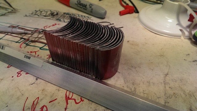 Anders flattened the trailing edges of the NGVs in order to keep the throat as defined and restrictive as possible, so we're doing the same.  We're also bending the tangs a few degrees to keep the NGV outlets from extending too far tangentially:  My friend makes the interesting point that a turbine is typically designed to fit the properties of the gas available from the core engine, and we're trying our best to make the gas fit our turbine and application. On this suggestion, I've taken to modifying our turbine by bending the leading edges toward axial, for more low-end torque: 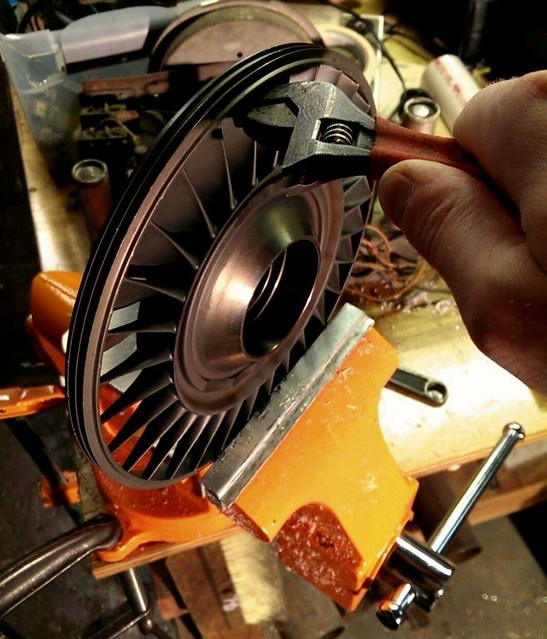 We'll keep producing blades, then profile the NGV set to fit inside the shroud. Joking of course, we wouldn't do such a thing to our turbine. - Feathers |
|
|
|
Post by Johansson on Mar 7, 2017 1:30:43 GMT -5
Great that my NGV fabrication pics comes to good use. :-)
You almost made me choke on my morning coffee there Feathers with the mention that you reprofiled the turbine wheel blades! Good one! :-)
Cheers!
/Anders
|
|
|
|
Post by pitciblackscotland on Mar 7, 2017 2:43:03 GMT -5
Hi Austin,
LOL for a sec i was thinking WTF!!! are you doing with that nice turbine wheel i sold to you.
Cheers,
Mark.
|
|
Feathers
Veteran Member
  
Joined: August 2010
Posts: 169
|
Post by Feathers on Mar 7, 2017 4:11:15 GMT -5
I've got to be more careful with jump-scare humor. An image like that could cause medical trouble for some of our members.  We've been taking very good care of our C-20 turbine. Even clamping it for that photo made me nervous. So far I think I've forgotten to thank John for his help with ballpark power turbine stage calculations! We appreciate the wise head over our shoulders while we meddle in big dangerous turbo-things. And I just keep finding new respect for you machinist types and your patience... You make all this look frustratingly easy... The NGVs look a little larger on a hub made for the 3rd stage C-20 wheel than the 4th stage! Minor diameter is only 4.5": 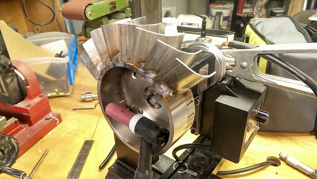 I'm doing my best to keep the alignment of these vanes through tacking and welding. Some hammer & pliers time will be necessary before we grind the tip profile. The tangs of each vane are welded to the inside of the hub, and the trailing edge of each welded to the outside of the hub. This will limit our ability to adjust things, but if she scoots, we're happy! 70° is the most we can twist the NGVs before running into flow issues, so we're set there, and we'll start blocking off throats or injecting water if we want more power. 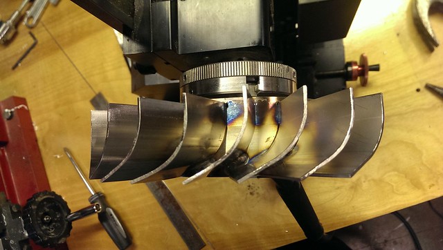 But on a junior chassis kart frame, are we really going to want more power? Thanks! - Feathers |
|
|
|
Post by racket on Mar 7, 2017 16:53:59 GMT -5
Hi Feathers
LOL, you won't be wanting more power ;-)
Cheers
John
|
|
Feathers
Veteran Member
  
Joined: August 2010
Posts: 169
|
Post by Feathers on Mar 11, 2017 3:27:49 GMT -5
The welding is actually complete! The vane tangs were welded into the NGV hub one by one. First a tack on the tang, then adjustment, then a full weld bead near the exit, then welding over the tang: 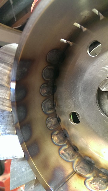   This next bit took some headscratching and some doing... The university shop doesn't permit grinding operations on or near their milling machines, so the "rotary table + grinding wheel + arbor + mill" configuration wasn't going to work. I have a very small Sherline mill with a taper-adapted lathe chuck. The speed is adjustable, so first we tried fixing an angle grinder to the bed of the mill, rotating the turret to horizontal, and slowly grinding away at the assembly: This may have eventually worked, but my nice dewalt grinder began producing some nasty smells. These machines are definitely not intended to run continuously, and I may have shortened the life of my tool by attempting this method. We went and purchased a very inexpensive bench grinder. We mounted a plate to the bed of the mill, and bolted the grinder to the plate so we could precisely adjust the axial position of the cutter in order to grind a perfectly cylindrical profile. Our bench grinder was also not happy about continuous-duty operation, so we began injecting shop air into the housing to keep it cool. It also did not rotate the correct direction, so we removed the motor start capacitor and hand-started it. The motor on the milling head had an adjustable speed dial, and we set it not to spin, but apply a constant small torque to automatically engage the vanes with the grinding wheel. When all was said and done, we had quite a jig. And while it was precise, the operation was very slow. It took over six hours to remove the bulk and true up the wheel: The end product fit very beautifully into the turbine shroud:   I've already welded the NGV hub assembly to the turbine shroud, I'll post pictures in a few hours after some rest. Thanks! - Austin |
|
|
|
Post by racket on Mar 11, 2017 16:05:05 GMT -5
Hi Feathers
A very nicely finished product :-)
LOL...............yep , grinding on my lathe leaves a horrible mess despite the layer of cardboard on the bed , thankfully its an old crappy lathe which I can't damage any more than it already is, maybe your university needs an old lathe in a "back shed" that can be abused for just these sorts of jobs.
Cheers
John
|
|
Feathers
Veteran Member
  
Joined: August 2010
Posts: 169
|
Post by Feathers on Mar 13, 2017 4:45:11 GMT -5
The shop managers are very picky creatures... We convinced the younger guy to let us grind slots in the NGV hub on a machine once, we had the mill dressed in magnets and shop rags. The NGV assembly (hub, NGVs, shroud, and plenum) is being welded right now. The first welds to be completed join the NGV+hub assembly to the turbine shroud. Small welds were made at the vane tips to the front of the assembly, then a more substantial bead at the vane tips toward the NGV exit: 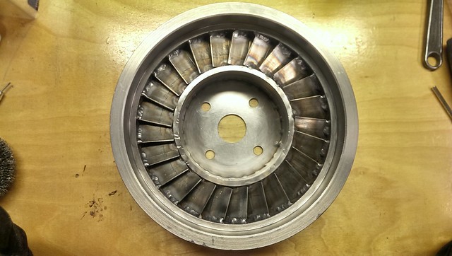 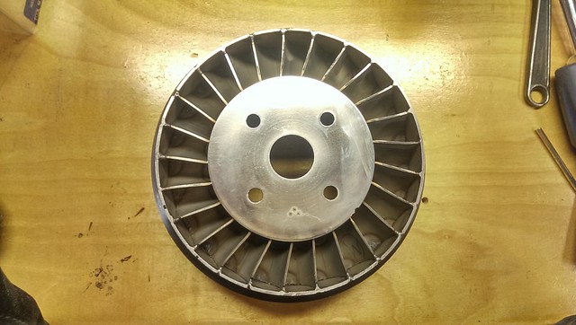 I did my best to relieve stress in the assembly by baking at 550°F for an hour, then letting cool in the oven. This had the side-effect of bluing the mild steel shroud. Looks pretty cool, but it will need a final coat of high-temperature paint. The C-20 power turbine section is dynamically balanced as an assembly when the 3rd and 4th stage wheels are aligned dead-nuts coaxial. We've got our little wheel all on it's own now, and are going to need the rotating assembly balanced. We have a shop to send it off to, so we went ahead and put indexing marks all over it to keep assembly consistent:  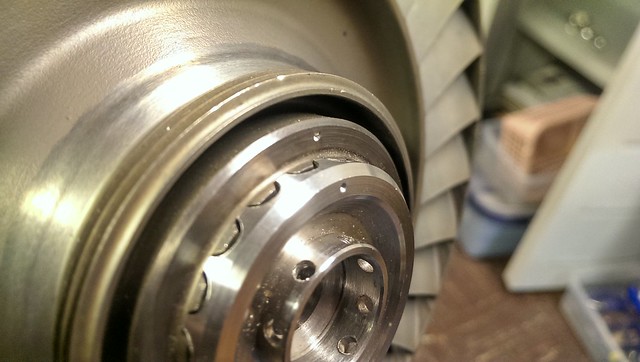 The part of this build that I've been dreading is the plenum. We don't have access to a slip-roll, and even if we did the parts are so oddly shaped that it might not even help. We've scrounged around for sturdy objects of an assortment of radii to beat the plenum pieces against in order to form them into shape. This job is going to take lots of hammering, cussing, tacking, grinding, and many head-scratchings. So far assembling the plenum has not been all that bad. Its fun when the assembly comes together just like your cad model: 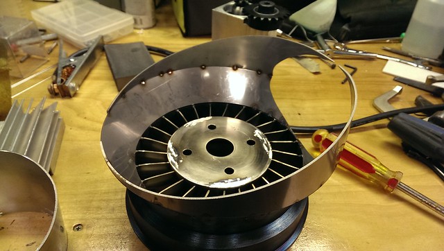 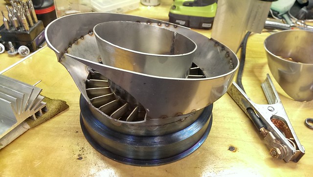 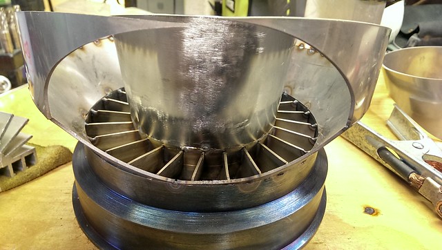 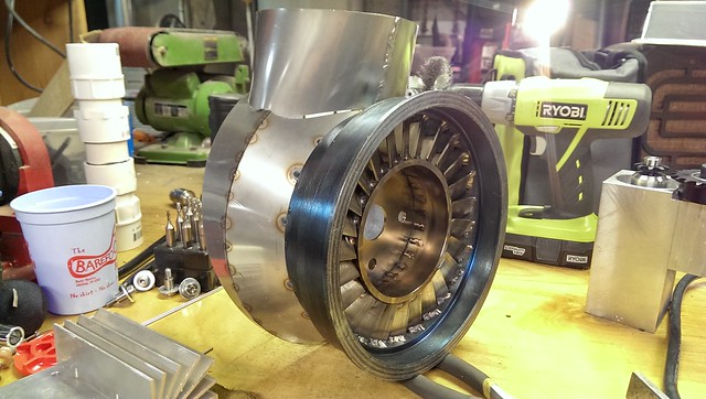 That transition from the round 5" interstage duct to the plenum inlet is going to be the most difficult to get right. The geometry doesn't lend itself to the "hammer and shop vice" method of forming. More head-scratching required. Thanks! -Feathers |
|
Chuks
Senior Member
  
Joined: August 2015
Posts: 498 
|
Post by Chuks on Mar 14, 2017 15:08:56 GMT -5
Wow!!!
I don't know how hard making a cad drawing is but bringing it to real life is a a big task...
Keep going and keep the pics coming, we need more to practice on.
Cheers
Chuks
|
|
|
|
Post by racket on Mar 14, 2017 16:21:49 GMT -5
Hi Feathers
Yep , plenty of indexing marks needed on rotating bits .
Your scroll parts are fitting together very nicely , CAD design sure beats my cardboard templates made from breakfast cereal boxes ;-)
Cheers
John
|
|
Feathers
Veteran Member
  
Joined: August 2010
Posts: 169
|
Post by Feathers on Mar 14, 2017 17:23:06 GMT -5
These photos make it look like everything fit perfectly... That transition piece might not be made to fit at all, what with all the stretching and beating it'll take to get into shape.
We'll see.
|
|