Feathers
Veteran Member
  
Joined: August 2010
Posts: 169
|
Post by Feathers on Feb 9, 2017 17:02:27 GMT -5
Thanks for the input guys, Unfortunately the design listed has been "set in stone", as we have a manufacturer cutting those flat patterns for our plenum. We're willing to accept some flow losses in order to make a more compact design, and simplify things a little bit. Our NGV section is very long, and contains 29 elements, so I don't think we'll be stalling the NGVs. Some ceramic coating will be in order. The turbine shroud turned out very well. Waiting on a band clamp now. 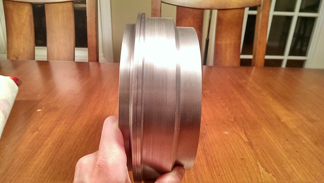 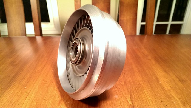 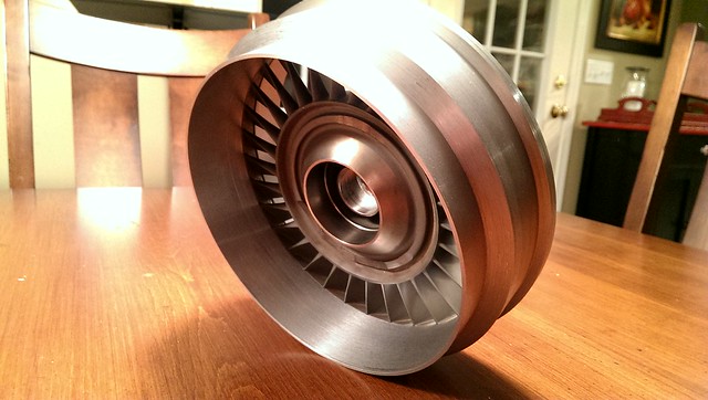 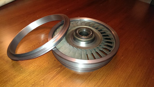 We've also finished machining the hot-side power turbine shaft components. This includes a nut to hold the turbine wheel on to the shaft, in addition to allowing the transmission of torque from the turbine's curvic coupling "teeth" to the shaft via slot and key. After finishing the turbine nut profile on the lathe, it was over to the dividing head: 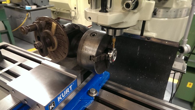 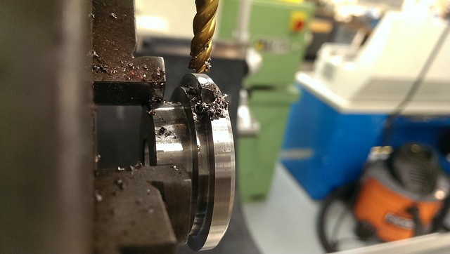 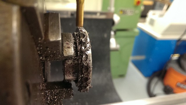 After verifying that the teeth fit the curvic coupling, we drilled holes for lockwiring the main turbine bolt in place. 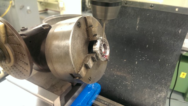 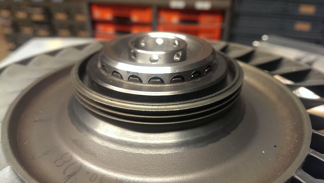 Its a perfect fit with the turbine. Because the curvic coupling (torque interface) is on the exhaust side of the turbine, we needed some mechanism for transmitting torque from the turbine nut to the shaft. We decided to accomplish this by milling a slot in the shaft, and milling a key out of the shaft-end of the turbine nut. 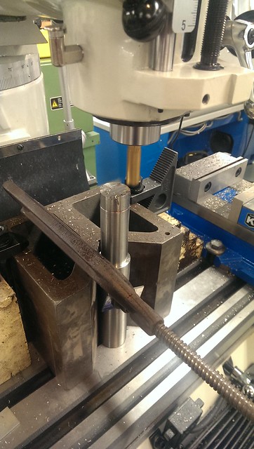 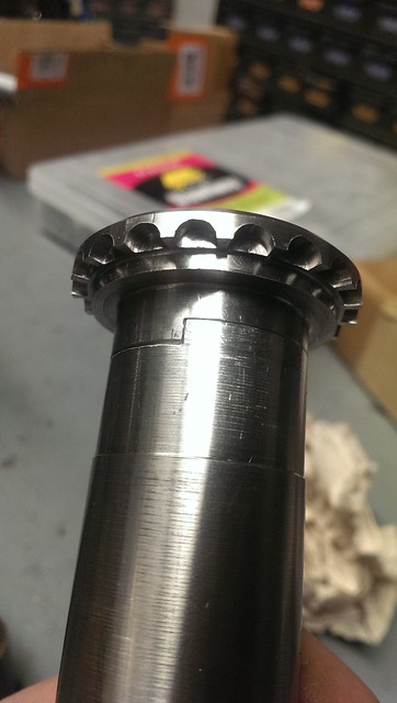 The fit was so tight that we needed lapping compound to get them to fit smoothly, but better to slowly approach finish dimensions in work like this  We also experimented with uneven spacing of the cross-drilled holes in the turbine bolt head, such that whatever angle our finish torque specification requires, we can fish some lockwire through. Unfortunately, this left the Allen bolt with very little of it's hexagonal internal socket left in one piece, so we welded a nut to the bolt for applying torque. 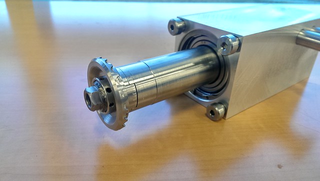 We assembled everything (turbine included, not shown) and dialed finished outer diameters of the assembly to runouts of 2-4 tenths. The finished assembly fits perfectly, and should run trouble-free for many years, fingers crossed. 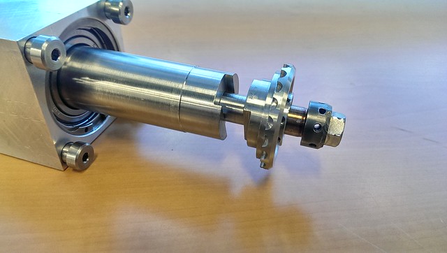 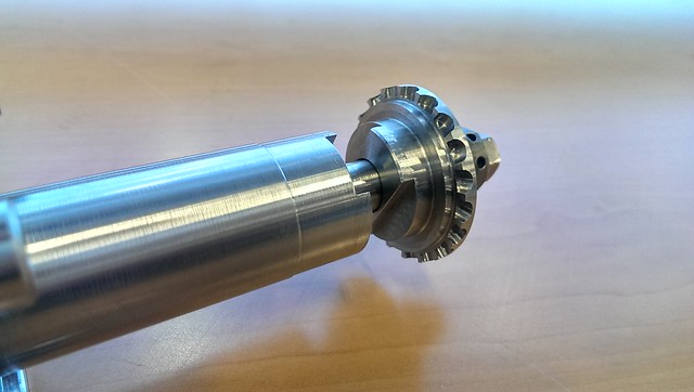 We also finished machining the outer diameter of the cold-side shaft end. The shaft is a shrink-fit to the cold-side bearing inner race, such that it can also help with axial loading. 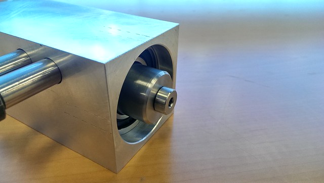 That's about it for now, we're crawling closer! Our team is contemplating a chain-tension interlock for fuel pump power, so if we throw a chain, our power turbine isn't allowed to freewheel too long. I don't know if anybody has experimented with an idea like that before. Thanks! - Feathers |
|
|
|
Post by Johansson on Feb 9, 2017 17:21:14 GMT -5
Very impressive machining Feathers!
|
|
|
|
Post by racket on Feb 9, 2017 17:50:00 GMT -5
Yep , very nice bits you guys have made , they should compliment the C20 turbine wheel beautifully .
|
|
bournaVee
Junior Member
 
Joined: January 2017
Posts: 66 
|
Post by bournaVee on Feb 10, 2017 5:48:41 GMT -5
hulo, john
how come the Free power turbine wheel is before the NGV?
isnt it suppose to be the other way around
|
|
|
|
Post by racket on Feb 10, 2017 15:01:13 GMT -5
Yep , NGV before wheel
|
|
Feathers
Veteran Member
  
Joined: August 2010
Posts: 169
|
Post by Feathers on Feb 13, 2017 1:35:18 GMT -5
Hey guys, I was wondering about your thoughts on something. Our original power turbine design used a "sleeve" that fit between the turbine wheel and "hot-end" bearing inner race. Pictured here (original design) in purple: 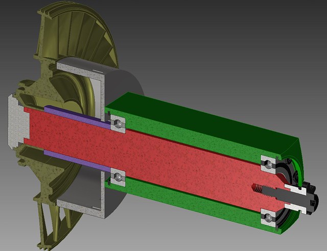 This seems to us a clumsy solution. If, for example, we go from idle to full throttle (~700*F EGT to 1000*F EGT in a few seconds), gas will leak into the region between the shaft and NGV hub. The sleeve could then become several hundred degrees hotter than the shaft for a moment (poor thermal conduction, much smaller thermal mass), and would want to expand length-wise by almost 15 thousanths of an inch! We're worried that this transient expansion may apply undue stress to the turbine, turbine nut, and the fastener & threads that hold the whole thing together. The solution we've come up with is a two-piece "collar" which fits around a shoulder in the turbine shaft. This collar has an inner diameter machined exactly to the outer diameter of the "shoulder" in the turbine shaft, and an outer diameter exactly equal to the large bore ground into the C-20 wheel. We would then use a slotting cutter to part the collar, and secure it with small fasteners around the turbine shaft. The system is shown below: The collar is in blue, in the cutaway drawings. The rest of the exposed shaft will be treated with a ceramic thermal barrier coating. 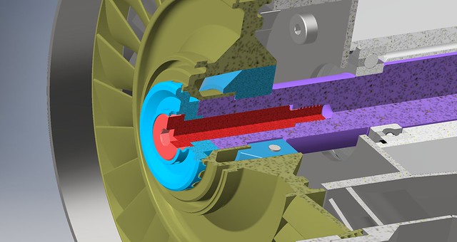 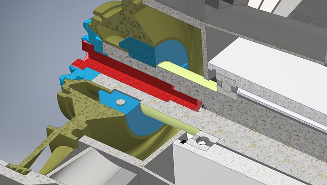 Here are some animations of the assembly and the fit of the collar to the shaft: Let me know what you think of the system we're considering! Thanks, Feathers |
|
|
|
Post by racket on Feb 13, 2017 3:44:58 GMT -5
Hi Feather Just feed a bit of bleed air into the cavity to prevent the hot gases entering, I feel you might be "overcomplicating" the problem. On my two shaft kart I had a drip feed of lube from the main supply along with bleed air fed into the shaft tunnel ( where the two red sealing caps are at the output end ) jetandturbineowners.proboards.com/attachment/download/51 the air and oil went through the bearings and out to the turbine wheel for a total loss system , the bleed air was also used as an air seal to stop lube exiting at the sprocket. Cheers John |
|
|
|
Post by jetjeff on Feb 13, 2017 5:20:55 GMT -5
Hi Feathers,
Outstanding work BTW. The only thing that would concern me is the distance between the power turbine and the first bearing.
Regards
Jeff
|
|
|
|
Post by racket on Feb 13, 2017 17:58:21 GMT -5
Hi Jeff
Yep , that overhang would be a concern normally if "full" rpm were to be used , but the chain drive will limit the rpm to a point where the overhang shouldn't be too much concern .
Cheers
John
|
|
gtbph
Veteran Member
  
Joined: August 2013
Posts: 101 
|
Post by gtbph on Feb 13, 2017 20:11:58 GMT -5
Hi Feathers, Very nice work! I like the sleeve design better than the collar because it does not have the screws. I would just make the sleeve a bit shorter to allow for expansion. I guess the turbine nut is tightened against the shaft and not against the wheel and the sleeve, so there is a bit of tolerance anyway, just make it a bit more. The turbine nut looks like it could handle that tiny bit of axial movement. Or else maybe a "springy" sleeve could provide a constant amount of axial force between the wheel and the bearing:  Alain |
|
Feathers
Veteran Member
  
Joined: August 2010
Posts: 169
|
Post by Feathers on Feb 13, 2017 23:03:48 GMT -5
Thanks for the input,
Racket, we will be using bleed air and oil to lubricate the bearings, so there will be positive pressure in that area. It may not be a problem to begin with.
The other benefit to the collar, however, is more substantial support of the turbine. The collar tightly fills a space between the disk rim, and the shaft.
Alain, The expansion sleeve is a very good idea. However, the turbine nut actually tightens against the turbine wheel itself, which will tighten against either: the sleeve, hot side bearing inner race, then shaft OR the collar, then the shaft.
The reason we need the sleeve or collar in the first place is because our hot side bearing ID is only very slightly larger than the turbine ID. The material available to form a shoulder, while still fitting the hot side bearing is minimal, and would not support the clamping load we hope to use. The sleeve or collar would supplement that.
I'm personally leaning toward the collar, but there are solid arguments for the sleeve. In the end, a friend of mine is machining these pieces (I'm traveling at the moment), so they will probably pick the simpler solution.
I'll direct them to your analysis here to help their decision.
Thanks for the input!
- Feathers
|
|
Feathers
Veteran Member
  
Joined: August 2010
Posts: 169
|
Post by Feathers on Mar 2, 2017 6:38:05 GMT -5
Much has been done to the power turbine stage, and it's almost ready to go. We finished the idler sprocket mount, which is required to keep the drive sprocket on the outside of the chain loop. The bearing was cooled with dry ice, then press-fit into the sprocket, and mounted. The fit is very tight (almost 0.002" diametric interference), and the dual-row angular contact bearing is riding slightly tight at the moment. We suspect it will wear in just fine: 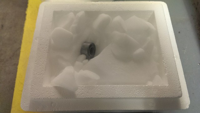 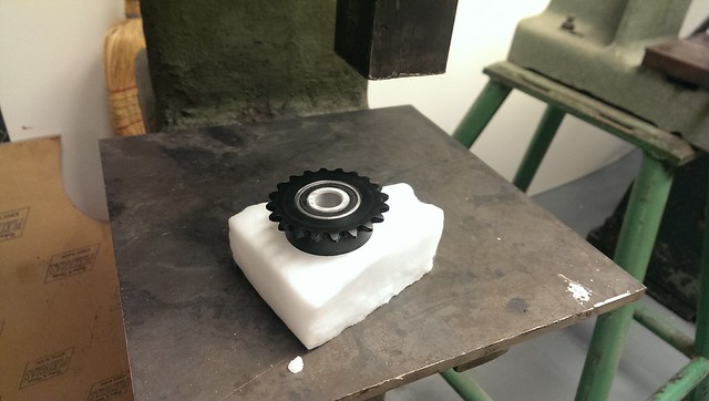 Put it all together, and it really looks like something: 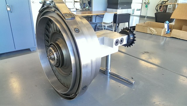 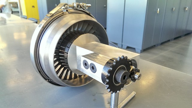 The chain fits very well, and we should be able to transmit a significant amount of power with a reliable tensioner keeping the slack side of the chain tight: 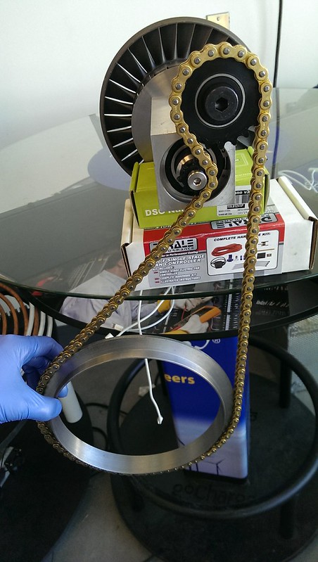 Also, our waterjet-cut sheets for the power turbine plenum have arrived! 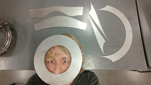 Now for the bit that I know next to nothing about. How do we decide on total flow area and NGV angles? I've got some aerospace engineering students who could help with calculations, but I'm a bit dumb myself when it comes to these things... We're really just looking for "Get 'er done" kinds of numbers... Our core engine runs well, and we suspect that it moves 1.1-1.2 lbs/sec of air, and we're shooting for a max N2 of 25krpm. The C-20 3rd stage is a hybrid impulse/reaction turbine, which makes things complex in ways that makes my brain sore. Measuring mass flow is a bit tricky given our equipment, so we'd like to take an educated guess in the dark and cross our fingers. Its gonna be FAST in any case, any real efficiency is just an added bonus. What do you guys think we should do for areas and angles? Any guidelines for this type of thing? Thanks! - Feathers and PESO |
|
|
|
Post by racket on Mar 2, 2017 16:45:11 GMT -5
Hi Feathers To determine your NGV throat area you need your total "energy" numbers coming from the gas producer and is the reason why I recommend guys build and test the gas producer as a pure jet engine initially. As a pure jet , if the thrust is measured accurately , and taken in conjunction with the jet nozzle area , jetpipe total pressure from a pitot tube , and jetpipe temperature , some simple calcs will easily cross check each parameter and allow a reasonable mass flow number to be calculated. Without an accurate mass flow number, jetpipe P4t and T4, its virtually impossible to determine a suitable NGV flow area . Theres rough calcs in here jetandturbineowners.proboards.com/thread/680/diy-turbines that you might be able to use , but without some hard data of your interstage energy levels , we're flying blind, change the temperature and we need to change the throat area , change the pressure and it will again change the resulting gas velocities and necessarythroat areas. If you have some "design" temperatures ( TIT) and pressures ( P2) I might be able to have a "guesstimate" of whats required. Cheers John |
|
Feathers
Veteran Member
  
Joined: August 2010
Posts: 169
|
Post by Feathers on Mar 2, 2017 18:40:18 GMT -5
Hey Racket,
Our max pressure ratio is 3.06 for max P2 of 30PSIG, with loaded full speed turbine outlet temperature of 1100*F and estimated TIT of 1350*F.
My aerospace friend suggested that our mass flow will likely be below 1.2 lbs/sec, which means that the C-20 turbine flow area is very, very large.
He suggested applying an NGV angle of 70 degrees, closing the throats as much as possible, and then blocking NGV inlets as necessary to extract more power until we've loaded the core engine to exhibit comfortable EGTs.
This is our guestimate so far!
Thanks!
- Feathers
|
|
|
|
Post by racket on Mar 2, 2017 20:09:50 GMT -5
Hi Feathers
Yep , your friend is in the ball park , my only query is the mass flow , how was that estimated??
Depending on your turbine stage scroll A/R, the mass flow can vary considerably .
Cheers
John
|
|


