stevep
Veteran Member
  
Joined: November 2012
Posts: 120
|
Post by stevep on Oct 18, 2013 18:53:10 GMT -5
Despite the silence, I've managed to make some progress, mostly in the form of removing obstacles to further work. First, on the voltage spike front, I have resolved that issue; not the way I wanted, but at least I am now able to move forward. During the experimentation that ensued after the previous update, I managed to slow the spikes down so my scope could resolve them into something more than just a vertical line. Turns out they consisted of a couple of cycles of ringing caused by the large inductance of the coil coupled with the capacitance in the other boards. Once I saw that it was ringing, I knew what the problem was and furthermore, realized that I would never be able to make it go away. Sooooo the resolution is to use a second battery and isolate the igniter circuit. Don't like it, but I'll do it. Second, regarding the valve/motor/gear issue, I tried to make the larger gear work but had enough problems that I retried getting the original gears to mesh. I managed to alter the mounting just enough to get the gears a bit closer together and that solved the problem. Whew! Tried the motor/valve combination with the breadboarded controller and it works pretty well. Third, I played with the new communication protocol that will allow the various boards to talk to each other. It took a while to get it going, but I managed to ferret out enough of the oddities that I was able to use it to write data to a memory chip and retrieve it. I had wanted to verify my understanding of the protocol before I started producing printed circuit boards, just in case there was something that differed from the documentation (it's been known to happen :-)). So with the protocol working and the voltage spike issue resolved, I felt comfortable moving ahead with the first board--the one that controls the two valve motors. I finished laying it out, etched it, and have just finished soldering it up: 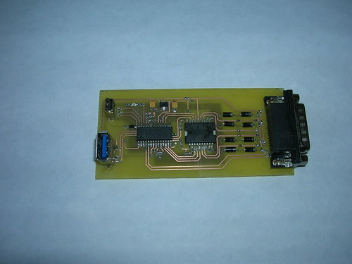 Big chip on the left is the cpu and the chip on the right is the motor controller chip (handles forward/reverse). This board will control both the nitrous and fuel valves. The cpu tells the motor controller which way to run the motor(s) and monitors the potentiometer(s) to tell it when to stop. It can do this for both valves simultaneously and independently (that is, one valve can be opening while the other is closing). Haven't tested it yet, but I'm sure it will work :-) --Steve |
|
stevep
Veteran Member
  
Joined: November 2012
Posts: 120
|
Post by stevep on Nov 3, 2013 14:11:12 GMT -5
The saga of the valve control board The good news is that it works. The first test was to see if the micro would run the motor properly (without any instruction from the main board). I managed to get that going in a couple of hours, so I turned to getting it to communicate with the main board so that the main board could say something like "Open valve #1" and the valve board would do it and report back to the main board what the result was (which would hopefully be "valve #1 fully open"). I ultimately succeeded as you can see in the following 15 second video. You can see the valve open, then close to about 1/2 way, then close fully (look at the bottom of the screen, the white gear with arrow on it): Getting to that point was a real saga and one which contains absolutely no rocket or metalworking information, so unless you're interested in electronics, you can skip the rest of this entry :-) The full story is too long and complicated to describe completely. Suffice it to say that the board started out looking like it was communicating in a very basic way, but when I went to add code to report back the valve position it stopped working. Thinking this was due to something in the last bit of code that I'd added, I spent a few hours trying to see what I'd done wrong. Finally I realized that even the basic stuff wasn't working. WTF?? Thinking I screwed something up in the last few hours of thrashing, I went over things in detail, but to no avail. After a couple of *days* of that, including tests with the scope and taking copious notes about each test that I ran, I began to conclude that a) it had *never* worked, even in basic communication mode, and that I had simply misinterpreted the results, and b) the chip simply didn't support the communication protocol the way it was documented to. I checked *everything*: re-cleaned the flux off the board (twice), eliminated the cable by soldering wires directly to the board, re-checked for the umpteenth time the circuit layout, re-checked the software umpteen times, re-read the documentation a bunch of times, checked the internet fro people reporting problems doing what I was trying to do, checked for "silicon errata" (euphemism for "our chip doesn't work the way we say it does")--all to no avail. After a few days of this, I tried a different communication protocol with the same result. Now this was really weird because that protocol worked just fine with the 40-pin variety of the chip I was using. Could it be some stupid hardware problem that existed only with the 28-pin version I was now using? It didn't seem possible, but it was starting to look like the only answer based on what I was seeing. Thinking that maybe in all my thrashing I'd somehow damaged the chip (which still *seemed* to work, but you never know with these things), I removed the chip and replaced it. Same result. On about the sixth day or so, I happened to be running a test that left the LED indicator (my only source of debugging info) on after the test finished and I noticed that the LED went off when I jiggled the board. Ha! Intermittent connection! So I futzed with that for a while and finally narrowed it down to the cable that connected the two boards. It was a very touchy thing--most of the time the cable was just fine, but if it got in exactly the right position, one of the wires shorted against the grounded shield, but it wasn't a dead short--just one good enough to draw enough current through the communication portion of the chip to damage that, but leave the rest of the chip apparently functional. Nasty!! Essentially I was getting random results for each of my tests. No wonder I couldn't figure anything out! The heck of it is, I tested that cable several times--when I first made it, then later when I started seeing weird results. I checked each wire for continuity, for shorts against the other wires, and for shorts to ground. But the problem was that a millimeter or two of one tiny strand (one of the strands of a 30g stranded wire--i.e., a *very* fine piece of wire) had sneaked out from the shrink-tubing I'd used to cover the joints. The cable had to be in *exactly* the right position to create the short which was why my checking hadn't identified the fault. And the fineness of the wire ensured that I'd have never spotted it with the naked eye (especially *my* naked eye). Fixed the cable, replaced the chip (again), and expected things to work, only to find that it still wasn't working. At that point I figured I needed to eliminate some of the unknowns, so I picked up a couple of chips that would fit directly in my breadboards. This eliminated the cable and the board as variables and allowed me to try the 40-pin version of the chip along side the 28-pin version. I started with the protocol I'd used a couple of years ago and which I knew worked with the 40-pin version. But now, not even that worked! Geez... Finally I realized that in all the software thrashing (I was now up to about a dozen versions of the test programs) I'd dropped 3 lines of "magic incantation" that was necessary to get the indicator LEDs to reliably light up. Again, a very nasty bug in that it gave essentially random results rather than simply just not working. Fixed that and the old protocol worked with both the 40-pin and 28-pin versions. Good--now if I had to, I could use the old protocol with the valve board and the new, faster protocol with the memory and a/d chips--slightly messy but entirely doable and I wouldn't have to scrap the valve board and start over. Then I tried the new protocol and of course it didn't work. It takes setting five or six bits in several different places in order to set up the chip to communicate--and of course the main board has to be set up to match. I'd been flipping these bits in various combinations (and there are a lot of combinations) thinking that there were only certain combinations, or perhaps only one combination, that worked, irrespective of the documentation's claims that they all worked. At this point, I'd been working on this problem for about ten days and my brain was pretty fried. Finally, early in the morning I spotted the problem: out of all the bits that affected the communication feature, I'd mis-set the one bit that actually turned the communication feature *on*--all the other bits affected the way the data was interpreted and if mis-set would have resulted in garbled communication, but at least there would have been signs that the chip was trying to communicate. But by not turning the feature on, the chip was simply not responding in any way! I can't be sure, because I ran way too many variations of the software to keep track of, but I think what happened was that I'd originally had the software correct (which explains the early success that I saw), but the cable issue clobbered me and either fried the chip immediately or some time later during the testing. In all the thrashing trying to get the fried chip to work, I dropped the 3-line incantation (causing erroneous success/failure reports) and either before or after that, mis-typed the setting of the crucial on/off bit which remained unnoticed through all the rest of the testing. Basically I had 3 problems, each masking the others, and doing so in a random way. I very much felt the way Winnie-the-Pooh must have felt that day walking around in circles, thinking he was tracking an animal when all the time he was following his own footprints: "Silly old Bear," he said, "what were you doing? First you went round the spinney twice by yourself, and then Piglet ran after you and you went round again together, and then you were just going round a fourth time" "Wait a moment," said Winnie-the-Pooh, holding up his paw. He sat down and thought, in the most thoughtful way he could think. Then he fitted his paw into one of the Tracks . . . and then he scratched his nose twice, and stood up. "Yes," said Winnie-the-Pooh. "I see now," said Winnie-the-Pooh. Anyway, once I got rid of all three of the problems, the board worked fine. One of the upsides to this whole thing is that I definitely gave those USB connectors a workout. I'd been a little concerned that mounted vertically they might not be sturdy enough to withstand repeated plugging/unplugging. I bet I exercised each of them over a hundred times and saw no signs they were coming loose from the board or being flaky. And I now have a very thorough understanding of this new protocol. But what a price to pay! And my poor little board--it is so much the worse for wear after all the unsoldering/resoldering. Ah well, at least it works.... --Steve |
|
stevep
Veteran Member
  
Joined: November 2012
Posts: 120
|
Post by stevep on Nov 15, 2013 12:54:02 GMT -5
Igniter Board When I etched the valve/motor board, I also did the igniter board (which will run the spark plug coil) but I didn't get a chance to test it until I got the frickin' valve board working. The part of the igniter board that runs the coil worked fine, but the circuit that detects whether the spark is actually being produced gave me some problems. Apparently it is touchier than I thought and it took a bit of futzing to get it to recognize the spark reliably. Along the way I devised a better way of doing that, but it's involved enough that I'm going to leave it as a backup strategy for now. However, I also discovered that my "I'll worry about that later" approach to dealing with electrically isolating the igniter circuit left a few things to be desired. I had originally thought that I could put the optoisolator components on the main board (and I probably still could) but after testing the igniter board it became clear that it would be better if I put them on the igniter board itself, which, unfortunately, was already etched and soldered up. Oops! Rather than scrap the igniter board and make a new one I just built a tiny "daughter board" that I mounted on top of the igniter board. This arrangement isn't as clean as I generally prefer, but it works and saved a bunch of time. The idea is that the main board raises the "enable" line which turns on the igniter circuit. At the same time it starts monitoring the "sense" line to make sure the spark is going. If it detects sparking, then it will send a signal to the valve board to open the nitrous and fuel valves. The "enable" and "sense" lines are what needed to be isolated from the igniter board-- and that's done by the two little chips on the daughter board: 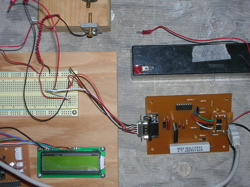 The igniter board is at the lower right, igniter battery at the upper right, spark plug coil and spark gap just visibile at upper left, and the prototyped main board is off to the left. The white cable plugs into the daughter board and connects the igniter board with the main board; the wires coming out the other end of the igniter board go to the coil and the sensing element (the coiled red wire). Next up (I think) is the A/D conversion board. I have it mostly laid out, but I need to check on a couple of components before I etch it and solder it up. Hoping to get all that done in the next week or so. --Steve |
|
stevep
Veteran Member
  
Joined: November 2012
Posts: 120
|
Post by stevep on Dec 19, 2013 11:07:23 GMT -5
Pushing pixels.... Things were going quite well with the A/D board until I got to the step where I make a paper copy of the board layout and check each component for fit. This time the part that didn't fit was the zillion pin A/D chip--the pad layout I had been using was too big, so a whole bunch of hours spent nudging traces to get things to line up properly was wasted. I thought I'd checked that I was using the correct layout, but in all the messing about with other boards I must have skipped a step somewhere. Anyway, I redid that part of the layout, then checked that I could still fit the DC-DC board on the A/D board; I couldn't so that meant tweaking the DC-DC board a bunch. By the time I'd done all that, I had reached my limit for "pushing pixels" and decided to get my hands dirty in the shop again. I have gone back and forth on what to use for a valve for the main nitrous bottle. A while back I mentioned that this valve would also be used to fill the flight tank when the time comes to actually fly something. Generally HPR guys use a solenoid valve for this operation (like what the car/bike guys use, only a souped-up version cuz it has to stay on a lot longer), but they're expensive and the orifices aren't all that big. They do, however, fail "safe" in that if the power is removed, the valve closes. The alternative, used by a few HPR guys down in Australia, is a motorized 1/4 turn valve like what I'm using for the throttle valves. The real drawback (to my mind) is the lack of a fail safe operation--if the power is removed (or the controller quits working), there's no way to turn the valve off short of manually doing so, and you might not want to do that, depending on what's going on at the moment :-) Finally I decided to go with a motorized valve, except that instead of using another valve, I'm just going to use the valve on the tank itself. It's a little harder to use in that it's a multi-turn valve and probably can be a little stiff, if the one on my CO2 tank is any indication, but I have a windshield wiper motor which is plenty strong enough, runs on 12v, and can be actuated with the same chip I use for the throttle valves. Position sensing will be done with a potentiometer, except this one will have to be a multi-turn one (because the valve is multi-turn). Turns out I have some gears that are just right, too. So now all I had to do was come up with a mount for the thing, the critical aspects being the correct axial alignment of the motor's shaft with the tank valve's shaft, and positioning the motor the correct distance above the valve. It was a bit fiddly, especially since I didn't have measurements for the mounting holes for the wiper motor and had to make some educated guesses, try out some paper templates, etc. Looks like this: 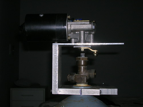 It turned out fairly well, however--quite solid and easy to mount/remove. What's left to be done is to create an arm to fit on the tank valve. This arm will have a slot to accept the ball on the wiper motor's arm (visible in the photo). I also need to mount the potentiometer. I don't have my actual nitrous tank yet so I just fitted it to my CO2 tank for now. I may have to make a different tank mount (the bottom plate) if the neck on the nitrous tank is a different size, but I needed something to test the electronics with, so the mount for the CO2 tank won't have been a total waste if I need to make a different one for the nitrous tank. I also started messing with the mount for the rocket motor and thrust-measuring load cell. I've needed a new one for testing some of my solid motors, so I'm taking the time to make sure this one can do double-duty. Nothing to show yet, but I have the metal on hand and some of it laid out. I've also spent a little time thinking about a simple mechanism for assessing how stiff the motor mount is--I'm hoping the motor mount will have low enough friction that I can detect a change in thrust of only a pound or so, but we'll see. Next steps are to etch the A/D and DC-DC boards, solder them up and test them, finish the wiper motor valve thingy & test it with some mocked-up electronics, and get the rocket motor holder/thrust-measuring load cell fabricated. --Steve |
|
|
|
Post by Johansson on Dec 20, 2013 4:02:12 GMT -5
Keep up the excellent work Steve, I have little of value to add to this thread so I keep my pie hole shut and admire your progress in silence.  Cheers! /Anders |
|
|
|
Post by ernie wrenn on Dec 21, 2013 9:13:22 GMT -5
You can change the bottle valve to a 1/4 turn inline. That will give you a faster opening. What size bottle are you going to use?
Ernie
|
|
stevep
Veteran Member
  
Joined: November 2012
Posts: 120
|
Post by stevep on Dec 22, 2013 17:22:19 GMT -5
Anders,
Thanks for hanging in there through all the electronics stuff....more metal work coming soon, I promise!
Ernie: I didn't know 1/4 turn bottle valves were available, but I'm pretty well set to go with the multiturn. Opening speed isn't an issue since there's a 1/4 turn throttle valve downstream. Looking at a 10-lb bottle. To start with :-)
--Steve
|
|
stevep
Veteran Member
  
Joined: November 2012
Posts: 120
|
Post by stevep on Jan 3, 2014 17:53:20 GMT -5
Load Cells I had originally planned to make several load cells for this project--I'll need one for measuring thrust, obviously, but I am also going to use load cells to determine propellant flow (one for nitrous, one for fuel). In the past I've made my own load cells, using directions found on Richard Nakka's web site (the strain gages were obtained from him, as well). Here are a couple of well-used ones: 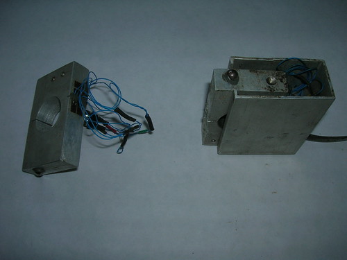 They're fairly easy to make and fairly inexpensive--maybe 20 bucks each if you don't get too fancy with the housings and connectors and you can easily size them to whatever force you plan to measure. However, I recently stumbled upon a source of incredibly cheap 50kg load cells--only $7 (plus shipping) which was just too good to pass up. I ordered 4 and they arrived a while ago: 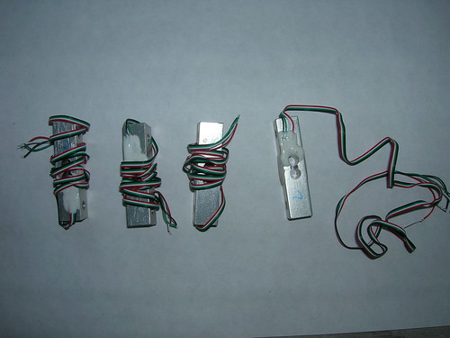 I finally got around to testing one, and they look to be decent quality and work as advertised. Glad I found them as they'll save me a bit of work. However, I think I'll beef up the wires with some type of covering or something--they're pretty fine and not overly robust the way they are. --Steve |
|
stevep
Veteran Member
  
Joined: November 2012
Posts: 120
|
Post by stevep on Jan 3, 2014 18:07:09 GMT -5
A/D board More progress on the electronics front. I managed to etch the DC-DC board and get it soldered up: 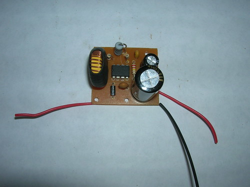 I could have made it smaller if I'd used surface-mount components (especially for the inductor), but I didn't see needing the through-hole components for a future project, so I just pulled them off the breadboard and used them. And here's the A/D board it will fit onto: 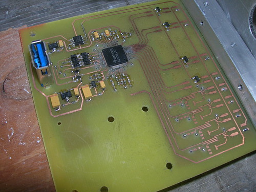 The actual A/D chip (the one with all the leads coming out of it) is about the size of my fingernail and the leads are about 0.5mm on center (with maybe half of that being the distance between the leads). I think that's the finest pitch I've ever done. Very fun to place and solder! I took my time and after I got the soldering done, made sure I tested every lead for contact and for bridging to the next lead. The technique isn't hard--just apply the minimum amount of solder that you can, then use solder wick to pull off the excess. Anyway, it *looks* fine so far. Some of the other components were a bit small, as well, but they went on fine. The DC-DC daughter board fits in the space at the lower left, but I just haven't had time to test it and get it mounted. The aluminum panel is for the pressure sensor connectors: 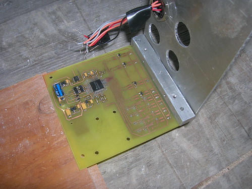 Once the leads from the connectors get soldered to the board, that's it--I can't remove the panel or the connectors except by desoldering a bunch of leads (possible, but a pain). I still need to cut the hole for the DB connector which will connect to the load cells. It's an irregular shape, so I'm sure that will be fun to drill/file out. Times like this, I really wish I had a mill :-) Also made some progress on other fronts: Main tank valve - got the arm fabricated and fitted to the wiper motor/tank valve. Haven't had a chance to test it yet, but it looks good so far. Motor mount: made a bit more progress, but need to make another run to the metal yard for more aluminum and around here such places aren't open during the holiday season. Here's what I originally thought might work: 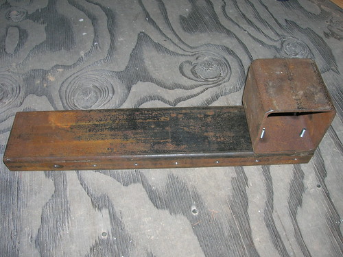 Now you'd think that would be very stiff, but when I clamped it to my table saw table and pushed on it with my hand I found that it deflected 20-50 thou so I decided to go with a different design: 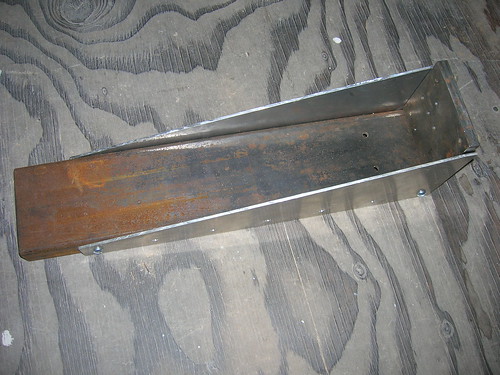 The bulkhead piece is just a scrap I placed in there to show the general idea--the actual bulkhead is waiting on my trip to the metal yard. The motor attaches to a sled (also awaiting more metal) that fits into the space between the side braces. The sled only has to move 10-20 thou so I'm going to put it on teflon pads to reduce the friction. Sorry I don't have a drawing to show the setup, but it isn't too dissimilar from other arrangements that have been used over the years by others. Next up: test the A/D board, but I have to write some software first. Also push ahead on the motor mount. And test the main tank valve setup, then get started on the board to run the wiper motor. Believe it or not, I actually see a light at the end of the tunnel: after the wiper motor board is done, the only electronic things left are the main board and the board for the hand-held remote control. Then I get to fabricate a metal box to house all the boards I've been building and the two batteries that run them. Somewhere in there I need to put together a metal test stand to hold the tanks, the motor, the sensors, and the control/data collection unit. Then it's back to the motor itself--I still have to fabricate the injector and test the whole setup for leaks. I have to say, I'm quite ready to be done with the test stand-related stuff and I'm really looking forward to getting back to motor fabrication. --Steve |
|
stevep
Veteran Member
  
Joined: November 2012
Posts: 120
|
Post by stevep on Jan 27, 2014 9:20:48 GMT -5
Motor mount for test stand We've been having unseasonably dry and warm weather here in the SF Bay area (leading to drought conditions), so I ended up spending a lot of time this past month or so working on the house and not much on rocket-related stuff. I did, however, test the DC-DC board and was gratified to see that it produced 28 volts just like the prototype did. I was also able to finish the fabrication for the main valve (windshield wiper motor) and tried it out manually--turned the valve on and off with no problem, so now I just have to add the electronics. But the really big effort went into the test stand mount for the motor. Here's the whole thing assembled:  Here it is from the side, with one of the side pieces removed so you can better see how it is put together: 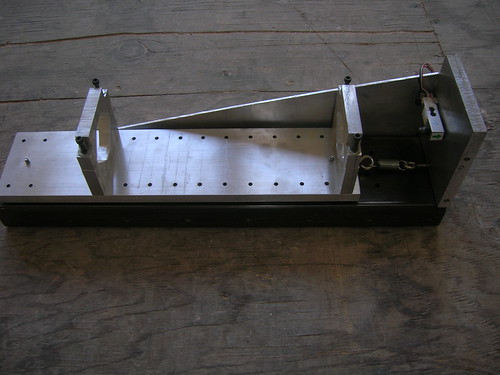 Here it is broken apart: 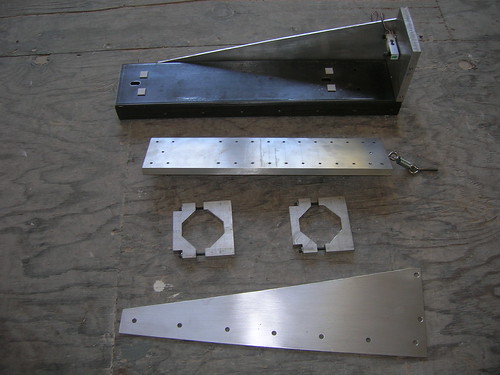 Here's the base without the sled: 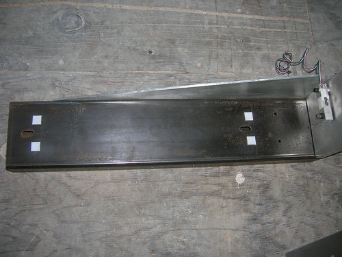 And the bottom of the sled: 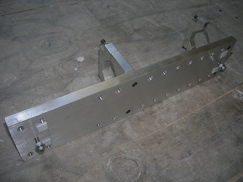 The first step was to get the bulkhead in place and test it for rigidity. I clamped the bulkhead down to my tablesaw table and pushed on the free end and it only moved 5-15 thou, which is way better than the 50 thou the other arrangement moved. I was hoping for a bit better, but I think it's going to be more than adequately stiff. Next up was the sled. The idea is it slides on some small Teflon (PTFE) pads (from McMaster-Carr) and is held in place by two pins that slide in the slots in the base. To register the thrust, the sled only needs to move 10-20 thou so the slots are way longer than they need to be, but by being longer than necessary they make it easier to position the motor in the sled. The motor mount brackets were designed to allow for a small range of motor diameters--from 2" up to about 2.5" (50-64mm) so I can use this with my solid motors which are a bit larger than the 2" I've been using for the liquid motor. Also, I put a bunch of extra mounting holes in the sled to allow for length differences in the motors--the solid motors are quite a bit longer than the liquid motor will be (width of the whole thing is about 4" (100mm) and it's about 16" (400mm) long). It will be used vertically, with the aft end of the motor down, firing into the ground. Here's a closeup of the bulkhead area: 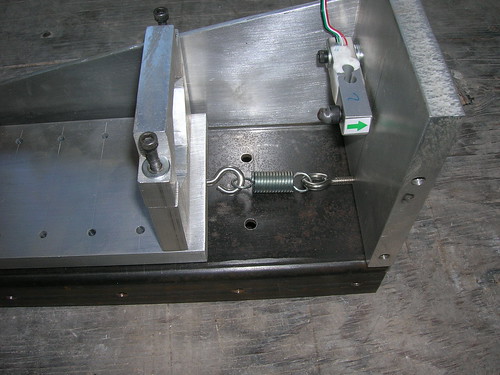 You can see the small load cell mounted on the bulkhead. I epoxied a small ball bearing ball into a socket head screw and screwed that into the load cell--that provides a nice bearing surface for the motor to thrust against. Since I didn't want the motor slamming into the load cell at startup, I added an adjustable spring mechanism to snug the motor up against the load cell. It was a little finicky getting the right spring and then getting the distance just right--the heaviest motor/pressure sensor I have seemed to be about 5 lbs (2+ kg), and the lightest will be about 1 (the sled itself is about 3). After some experimentation I arrived at an arrangement in which the spring will put a pre-load of several pounds (1-2 kgf) on the load cell (after subtracting the weight of the sled/motor) and I'll just subtract the preload amount when I do the data reduction after the test. In use, the motor is mounted in the sled like this: 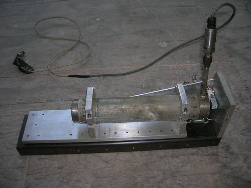 The sled is positioned in the middle of its range of motion (limited by the pins in the slots) and the motor's position adjusted until it just kisses the load cell. Then I position the whole thing vertically so gravity pulls down the motor/sled just as it will during the test and tension the spring using an adjustment nut on top of the bulkhead. I was concerned about the hot exhaust gasses destroying the sled, especially when using a short motor, so I ran a quick test with a propane torch. I held the torch so the flame was parallel with and about an inch away from a 1/2" thick piece of aluminum. After 30 seconds the aluminum wasn't even warm! I tried putting the flame almost next to the aluminum and it still didn't warm up enough to make some water droplets sizzle, so I think the sled will be fine. Next up is to make a small test jig to determine how much force it takes to get the sled to register on the load cell. It won't be anything fancy, just a small teeter-totter affair with provision for some weights at one end. After that it's back to electronics.... --Steve |
|
gidge348
Senior Member
  
Joined: September 2010
Posts: 426 
|
Post by gidge348 on Jan 27, 2014 19:37:42 GMT -5
Hi Steve,
Maybe if you are worried about heat damaging the sled you could attach some exhaust pipe lagging it is very cheap and quite effective.
Ian...
|
|
stevep
Veteran Member
  
Joined: November 2012
Posts: 120
|
Post by stevep on Jan 29, 2014 19:26:30 GMT -5
Hey Ian,
Thanks for the suggestion. I wasn't familiar with the term "lagging" but after googling around a bit I discovered that there is no shortage of products to choose from!
--Steve
|
|
stevep
Veteran Member
  
Joined: November 2012
Posts: 120
|
Post by stevep on Feb 18, 2014 18:45:25 GMT -5
Injector I know I said I was going to tackle electronics, but for some reason the injector has been on my mind a lot recently, so while I was messing around in the shop with the test stand motor mount, I just decided to tackle the injector and get it done and off my mind. Here are the components: 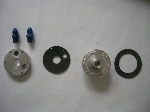 From left to right is what I'm calling the top plate, then the gasket which goes between the top plate and the injector, then the injector itself, and the gasket which goes between the injector and the combustion chamber. I have two (of the three required for testing) AN fittings at the upper left. Here are the other sides of the top plate and the injector: 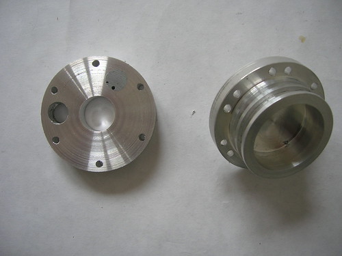 And here's the injector from the side, with the AN fittings in place on both the injector and top plate. 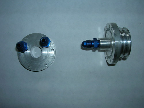 Here's everything put together with the chamber: 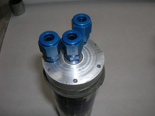 And from the side: 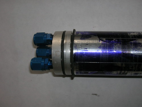 The AN fittings are "dash 4" because that's the smallest I could find that mated NPT to flare. They're a tight fit, but there's just enough room to turn the nuts if you put them on in the right order. The way this all works is that the nitrous line will attach to the spigot (via the AN fitting) portion of the injector and flow straight through the (yet to be drilled) orifices into the chamber. This was designed so that there would be no need for a gasket to separate the nitrous from anything and (in the flight version) to give the nitrous as straight a flow into the chamber as possible. The fuel flows through the unplugged hole in the top plate, through the hole in the top gasket and into the groove that runs around the injector. This groove then empties into six holes that match the "down" holes in the chamber. The groove is about 0.125" (3mm) and the up/down holes in the chamber are the same. The last AN fitting (and hole in the top plate) is for the pressure sensor. This ended up being a bit of a hack in that when I cut the groove I was thinking of how it would be for the *flight* version (which won't have the pressure sensor) and not how it needed to be for the *test* version. Consequently when I drilled the hole in the top plate for the pressure sensor, I realized the fuel would flow through the groove and up into the pressure sensor--not what I wanted. The hole in the top plate had to be a through-hole because my tap for the NPT threads needed to go "out the other side" of the hole to thread properly. So I went ahead and threaded the hole, then plugged the bottom bit with some epoxy (visible in the photo). This epoxy plug will fit flat against the gasket so that fuel won't leak out of the groove under this hole. Then I drilled a tiny hole in the injector, between the fuel groove and the spigot. This hole communicates with the inside of the chamber--it's just barely visible in the photos. There is a corresponding small hole in the gasket which fits between the top plate and the injector. Lastly, there is a corresponding small hole in the epoxy plug. The flange on the the injector fits into the combustion chamber and has two grooves--one is for the fuel that comes out of the "up" holes in the chamber and the other is for an o-ring which will seal the injector against the chamber. There are six radially-drilled holes in the chamber that allow for the fuel to flow out of the up-holes, through the chamber wall, and into the groove in flange of the injector. They're just barely visible here; look just below the end of the chamber: 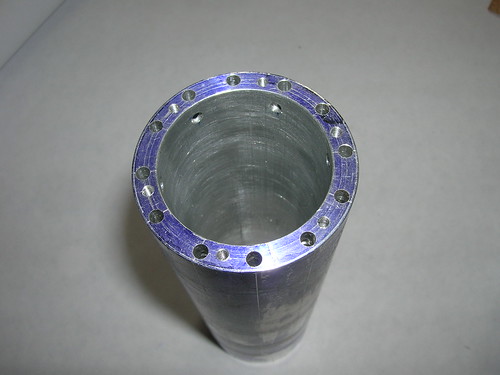 So the fuel flow is this: through the AN-fitting in the top plate, through the hole in the top plate, through the hole in the gasket, into the groove in the face of the injector, out (toward the edge of the injector) into the six down-holes, through the down holes in the chamber, around the end of the chamber, up through the up-holes, then through the holes in the wall of the chamber into the groove in the flange of the injector, then through (yet to be drilled) holes in this groove and out into the chamber (see the test version of this arrangement that I diagrammed and tested some time ago--see the posts in page 4). Fabrication (other than the craziness for the pressure sensor) was straightforward. I cut the groove in the face of the injector with an end mill chucked in the electric drill mounted on my lathe's tool post which I showed back when I was making the chamber itself (page 5). The rest was just straightforward turning. The only slightly tricky part was to line up the holes in the top plate, the injector, and the chamber while leaving enough room (I hope!) for the gasket to seal around them. Speaking of gaskets, cutting them took a bit of messing around. You can buy punches for this sort of thing, but the larger ones get expensive (about $100 for a 2" (50 mm)). I wondered if there wasn't a cheap way of doing it, so as a test I just chucked a piece of steel tube in the lathe and cut the edge at an angle to make it sharp. I then put this along with a piece of rubber and a piece of wood for a backer into the vise and squeezed the heck out of it and presto! one very tidy 2" hole for the price of a piece of scrap tubing. Elated, I found bits of tubing that were the right sizes for the other holes and sharpened them in a similar way. They all worked fine, even a punch made from copper tubing worked well. Then it came time to do the 0.125" holes around the circumference--now there was a problem in addition to making the hole: locating the holes accurately. After some head scratching I found a bit of 0.125" OD brass tubing that with a bit of sanding fit nicely in the holes in the injector. I sharpened the edge of the tubing, not in the lathe (because I didn't have a tool that would fit inside the tube), but with the point of a "spade" bit (I just turned it a few times by hand). I then fit the gasket to the injector, placed this against a wooden backer, and being careful to keep everything together, put the hole punch through the injector and whacked the punch with a hammer. I then continued on around the injector and was gratified to see that all twelve holes lined up quite well. Here are the finished hole punches together with the gaskets: 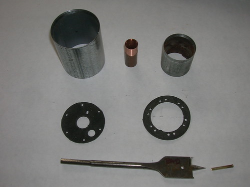 The spade bit I used to sharpen the brass tube is also shown. One needn't restrict oneself to tubing--the end of a solid bar could be turned down to the diameter needed for the hole, then a hole drilled a short distance into the end of the bar (making the end tubular) and sharpened just as I did with the tubing. You would then drill a hole the length of the punch to allow a small rod to be inserted which would be used to remove the punched material from the punch. I don't know (yet) whether these punches will be workable with materials other than rubber--I may end up needing graphite gaskets and they may not cut as easily or as cleanly with punches made this way. At this point I'm waiting for some socket head cap screws of the correct length so I can attach the injector to the chamber. Once I do that, then I will pressure test the assembly to see whether my gaskets leak (that's one of the reasons the fuel orifices weren't drilled). Assuming I can get things to be leak-free, then I will need to use the old test injector, my as-yet-unbuilt test stand, and yet-to-be-finished electronics to calibrate the nitrous and fuel flow at realistic pressures. Once that's done, I can go ahead and drill the orifices in the real injector (which is the other reason I didn't drill the orifices). ============================== In other news, I played with the test stand motor mount a bit. I hooked up my old data collection system (the one I use with solid motors), recalibrated it for the new load cells, and placed some loads on the thing to see how sensitive it was. It turns out to take only about 1/4 pound (100 g or so) to consistently register a measurable difference. That's easily sensitive enough for a motor that's producing 50 lbs of thrust. I'm sure things will stiffen up once I attach the fuel and nitrous lines to the motor, but I played around with some copper tubing just to get a feel for things and I think I can still achieve one-pound (450g) sensitivity. Stay tuned.... --Steve |
|
stevep
Veteran Member
  
Joined: November 2012
Posts: 120
|
Post by stevep on Feb 26, 2014 11:58:36 GMT -5
Leak Testing Once I had the motor completed, the next step was to test for leaks in the coolant channels. The procedure for this is much like bleeding brakes: fill the system full (*completely* full) of fluid, then gradually bring it up to operating pressure while checking for leaks. Except in this case, not getting all the air out leads to two problems, one annoying, the other dangerous. The annoying problem is that my piston for pressurizing the system has a limited stroke so that any air in the system results in a lot of "sponginess" and the stroke won't be sufficient to get up to pressure. The dangerous problem is that compressed air (especially at, say, 1000 psi (69 bar) ) has a lot of energy and if something lets go at that pressure, well, you don't want to be anywhere near it. Water doesn't compress, so it can't store much energy and when something lets go (assuming the system itself isn't elastic) you just get a bit of a "whoosh" and a watery mess. Hence, the desire to remove all air from the system before pressurization takes place. Here's my cobbled-together hydrostatic pressure testing arrangement: 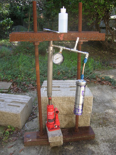 It's basically just a hydraulic press that squeezes a cylinder/piston filled with water. The cylinder connects through fittings to a pressure gauge and to the device under test. The system is made from components that are rated at about 6,000 psi but I've never achieved pressures greater than 1800 psi (124 bar) because it starts leaking at that pressure. You can see the motor (splotchy purple thing) hanging off the end. This whole arrangement is a bit inconvenient to use, but it gets the job done and I don't use it often enough to warrant spending a bunch of time to make it more convenient. Anyway, the fact that the system has to be full of water with no air in it, means that all those cooling channels in the chamber need to be filled with water. The only sensible way (and please don't ask how I know this) is to assemble the chamber under water (in a large bucket). My first attempt at this was a dismal failure--lining up all the parts (especially the injector: two plates and two gaskets) under water proved to be messy and difficult. A better way is to partially assemble it all with the screws just started in their holes, but with plenty of gaps between the parts for water to flow in and air to flow out, then to immerse the thing and start tightening it up while it's under water. Doable, but it's painful because getting a grip on a wet 3/64 (1.2mm) allen wrench ain't easy. I finally got the thing full of water and assembled it, only to find that it leaked like crazy at 0 psi! WTF?? Turns out the screws were bottoming in the holes--they felt tight but weren't compressing the gaskets. Fortunately, I'd thought ahead and ordered screws of varying lengths, so I substituted shorter screws (repeating the whole immersion thing) only to find that it leaked like crazy at barely any pressure at all. Tightened things down to the point where the gaskets were extruding out around the edges and it still leaked. Kept checking the pressure gauge and it kept reading "0" all the while water was spraying out (in a very fine mist) in all directions. This was very odd because in all the drop size experiments I'd used this same rubber and had no problem getting things to seal, even at 125 psi (8+ bar). However, (and this will tell you just how obsessed I seem to be about drop sizes even though it's been months since I last dealt with the issue), I *did* immediately notice that this was a much finer spray than I'd been able to achieve in the past and it suddenly dawned on me that I'd "discovered" another way to make an orifice: scratch a groove in one plate and screw that to another plate (separated by a gasket)! Depressed about the leaks but curious about this new approach to orifice-making, I spent a few hours making up a test article and attaching it to the water tank + shop air apparatus that I'd used in the drop size experiments. Nada. Not a drop came out. Loosened the screws that held the plates together and finally got a lackluster dribble to come out. WTF #2?? Then I realized what had been happening: the gauge on the hydrostatic test system was not registering correctly! Clearly at 125 psi, the gasket was easy to seal; clearly at 125 psi there was no way I was going to make the fine spray I'd seen with during my leak testing. Obviously the pressure *had* been high (perhaps very high) and the gauge just wasn't telling me. Swapped out the gauge and retested. Still got the leak (and the spray), but it was up around 200-400 psi. Tightened the heck out of everything and it still leaked. Reworked the injector to put ridges in strategic places on the theory that I'd get greater compression in those areas (and give the gasket room to expand in others). That helped a bit, but nowhere near enough. Judging by the amount of extrusion I was seeing, I have tentatively concluded that a) my gasket material is too soft, and b) I may not have a design that won't leak no matter what I do. To address (a), I'm ordering some harder material. To address (b) I have decided to implement a new chamber design I've been thinking about ever since I spent a zillion hours drilling those deep holes in the existing chamber. Meanwhile I connected the scratch-orifice test article to the hydrostatic tester and cranked up the pressure as best I could, but didn't get much of a spray. This looks to be one of those things that might be harder to achieve on purpose than it was to achieve by accident. It's still an intriguing idea, and I can see a way to turn it into a usable injector, but I'm going to set it aside for now and focus on getting a chamber that actually holds water. --Steve |
|
gidge348
Senior Member
  
Joined: September 2010
Posts: 426 
|
Post by gidge348 on Feb 26, 2014 19:22:38 GMT -5
Hi Steve,
I think you may have problems with the current design using flat gasket's/seals.
These would be fine if the pressure was external pushing inwards or the flange was much wider or the pressure lower.
My main worry is that at several 10's of bar you will not be able to stop deformation of the gasket/endplates or stretching of the bolts. Any tiny move of these and you will have a leak.
I know it's a pain but I would look into putting 1 or 2 "O" rings in the bore of the tube and/or 1 or 2 on the face of the sealing plates.
With an O ring the more the pressure builds and the more it deforms the better the O ring also deforms to take up the space.
Try your new gasket material, but think this may be an option.
Cheers
Ian...
|
|


