Flow testing the motor
After I got back into town, things started to move ahead quite nicely. The fuel tank I've been using for my testing had only been tested with shop air at 125 psi (8.6 bar), but it will need to handle pressures higher than that, so I spent some time pressure testing it up to about 1200 psi. As expected, this went smoothly with no leaks.
Then I repeated some flow measurements with the old prototype injector I was using for drop size experiments. A long time ago I'd measured the flow at 90 psi, but I was curious if higher pressures would cause the Cd factor to change at all, and, of course, there's nothing like having real measurements as opposed to calculated results. I pressurized things with CO2 (800 psi, roughly) and boy does that make the water flow! However, this process didn't go smoothly because the orifices were 0.013" (0.33 mm) and there was a lot of junk in the tank and plumbing lines that kept clogging the orifices. Visited a kitchen supply store (of all places) to get some stiff-bristled brushes of the right diameters for the tank and other parts and I practically oxygen-cleaned the whole setup. That's also when I decided I was tired of cleaning the orifices using those delicate drill bits, one of which I dropped onto the shop floor and broke, despite it landing in a pile of sawdust.
So I ordered up some lengths of small diameter piano wire, waited for that to arrive, and started using that for cleaning the orifices--much better! Also, I decided I was tired of holding the injector up to various light sources at just the right angle to see if the orifices were clogged, so I futzed around and made a more usable light source:
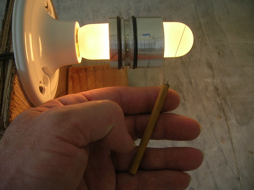
What an improvement! (If you wonder why rocketry takes time, it isn't building the rocket that takes forever, it's finding/building all the rest of this stuff that slows you down.)
Once I got rid of all the clogging, the next obstacle was reading the pressure gauge and accurately setting the pressure. Running tests at just 400 psi were emptying the tank in ten seconds or so, and between watching the gauge and my watch while also being ready to shut off the CO2, it was difficult to see that the pressure was right. At higher pressures things happened too fast to get reliable results, so I ordered up some inexpensive but easy-to-read gauges; once they arrived I found things went much more smoothly, but it still took almost half a day to get a set of measurements I was happy with in terms of accuracy and consistency.
These measurements showed that the Cd was pretty constant up to 400 psi or so (the limit of my testing). The next question was what effect would the cooling channels have on the pressure, but to test that, I needed the real injector which still needed to have its holes drilled to 0.013". To drill the test article had taken a lot of time and effort and I was always running the risk of breaking drill bits, so I ordered up another ten bits, just in case.
As it happened, I had to turn a small part for a different project, got fed up with the backlash in my cross-slide, and took a few days to make an "Evanut"
bbs.homeshopmachinist.net/threads/43645-Making-Acetal-leadscrew-nuts-the-easy-way out of acetal. Wow, what a difference! Zero (and I mean zero) backlash. Micrometer-like smoothness, repeatable accuracy, and it really cut down on the chatter during parting operations. If you don't have one, make one--you'll love it! At the same time I finally decided to spring for a gallon of Vactra #2 way oil--that, too, really makes a difference--wish I'd done that a few years ago :-)
Then I got fed up with not having a real carriage stop--I had been using a clamp and steel bar--so I took the time to make one of those. Then I got ticked off with one of the chuck keys for my 4-jaw and ordered a new one--it was oversize so I had to carefully grind it down to fit.
Then I really succumbed to temptation. I've been drilling those super-tiny precision holes on the drill press, but it's hard to do and the sensible way is to just chuck the cylindrical injector in the lathe and drill them there. But my drilling arrangement there is even less rigid/precise than the drill press, so I've never even attempted it. I've long known that what I should have is a decent toolpost-mounted spindle which I could use for both drilling and light milling for things like the cooling channels. Trouble is, I've never seen one that I could afford, or that seemed robust enough, or that would mount the way I wanted it to, etc. I've also casually considered making a spindle, but all the build threads I've seen seem to have been done by folks with way more skill than I believe I have (not to mention probably more accurate lathes), so I've not proceeded down that path. As a result, I've just kept on using the clamped-drill arrangement or the drill press.
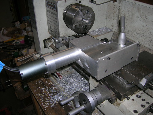
But I guess my frustration level must have risen to some critical, threshold level, because I found myself rereading a bunch of spindle building threads and I just decided to give it a go. I didn't need super accuracy or super-high speed, so I figured that would make it easier and cheaper. Long story short, I built one out of $14 deep-groove (not AC) bearings, a cheap ($20) ER 16 straight shank collet chuck, and and a brushless DC RC motor and associated electronics. Total cost was less than $200 for the spindle itself. The toolpost mount (a big chunk of aluminum) cost me another $30.
I spent the better part of 3 weeks standing in front of the lathe for about 4-6 hours per day--thereby making it the most complex, most precise, time-consuming bit of machining I've ever done. But miracle of miracles, it works!
And it works far better than I had any right to expect, given the low cost of the parts and my inexperience at this sort of thing: it has a few tenths runout 1/2" from the nose of the chuck. I can mill a 1/4" wide, .050 deep slot in aluminum and drill those tiny 0.013" holes.
Here it is, set up for radial drilling:
And here it is, "flopped" for axial drilling:
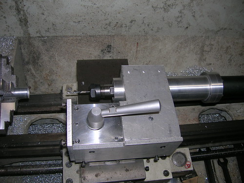
The really cool thing is that I can just place it on the tool post and it's perfectly aligned, doesn't matter which orientation. To change orientations with the clamped drill, I had to remove the drill from the clamp, turn it around, rotate the tool holder, reclamp the drill and realign it (in both pitch and yaw) which was never fun. This setup is *so* much more convenient--as long as my compound is accurately aligned (which it is nearly all the time), the spindle goes on perfectly aligned. Changing orientations just involves turning it over and rotating it--the spindle doesn't have to be removed from the mount and no realignment is necessary.
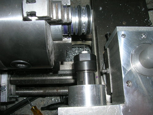
It sure took a bite out of my rocket-building time, but it is a great joy to use, so it was well worth it. And I did finally get my injector holes drilled....didn't break a single bit!
Now it was time to run the flow test with water. Naturally nothing went smoothly. First, it took a zillion runs to get all the orifice-clogging crap out of the motor. I'd cleaned it with a toothbrush and soap/water, but there was a lot of stuff hiding in the crevices that found its way into the orifices. Finally got a few runs in, but ran out of CO2. Went to my usual supplier but found that they'd shut down my local outlet, so I ended up spending a day scouting around for a supplier that was nearby but didn't require opening a corporate account.
Found one, but he only supplies aluminum tanks which have a much larger diameter neck than the steel tank I made my valve for, so I'll have to rebuild the clamp for that. While I was there I asked about nitrous--all he supplies is 50 lb cylinders but the price is pretty good: less than $3/lb but the tank will cost me $260 and it will weigh 100 lbs when full which makes it a pain to deal with. Gotta do some more looking, I guess.
Anyway, went back to flow testing but now the "fuel" (water) tank started leaking for some reason. Chased that for a couple of days, then went back through the test-until-the-orifices-stop-clogging routine. Finally after a couple of days of actual testing I got a set of data I think is reliable.
Seems like my cooling channels plus the injector only create about a 100 psi (7 bar) pressure drop which is somewhat less than I'd calculated (always good). I wanted a drop of about 100 psi across the injector itself, so that plus a chamber pressure of 250 psi (17 bar) means that I need a pressure of about 400-450 psi (27-31 bar) on the tank itself. Given that CO2 at room temp is about 800 psi, I have a decent margin to play with.
OK, that's with water--my fuel is going to be diesel #2 meant for vehicles here in the States--I have no idea what it's called elsewhere. Since it could have flow characteristics different from water, it was time to buy some and start testing with it. Testing with water tended to result in water all over the place (spills while filling the tank, spills/splash as the motor ejects the water, etc.) and I wasn't looking forward to having diesel fuel all over the place, so I spread some plastic sheeting around to contain as much of it as I could, and used larger vessels to capture output and any spills during tank filling--both of which helped. Anyway, here's the results:
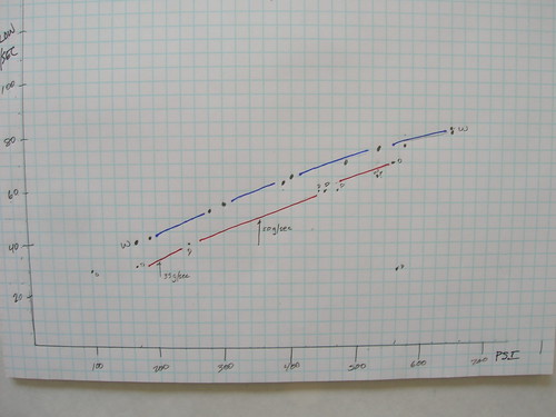
The X-axis is pressure (psi) just before the motor, the Y-axis is g/sec of fluid (water-blue, diesel-red) that flowed through the motor. A couple of observations: first, the diesel is about 80% as dense as water and it appears that the difference between the lines is about this magnitude. That tells me that the diesel is flowing just about the same as the water did, which is cool, since it means I can keep testing with water and just correct for the difference in density (less mess, less smell).
Second, as I indicated above, I'm getting plenty of fuel flowing through the motor. If I go with a 75/25 nitrous:fuel ratio, I need 32g of diesel/second and if I go with 65/35, then I'll need 50g/sec. In the case of 32g/second, a tank pressure of 450 psi will suffice and for 50g/sec I'll need 600 psi in the tank (see small arrows on the chart).
At this point I'm a happy camper. I have an injector that works, cooling channels that don't leak and don't create a huge pressure drop, verification that the real fuel will flow adequately, and a fuel tank that seems to work, along with a way to pressurize it. And a new toy for my lathe :-)
Now I really must finish up the electronics....
--Steve